R. Brighenti et alii, Frattura ed Integrità Strutturale, 34 (2015) 59-68; DOI: 10.3221/IGF-ESIS.34.05
59
Focussed on Crack Paths
Effect of fibre arrangement on the multiaxial fatigue of
fibrous composites: a micromechanical computational model
Roberto Brighenti, Andrea Carpinteri, Daniela Scorza
University of Parma, Italy[email protected], [email protected], [email protected]
ABSTRACT. Structural components made of fibre-reinforced materials are frequently used in engineering applications. Fibre-reinforced composites are multiphase materials, and complex mechanical phenomena take place at limit conditions but also during normal service situations, especially under fatigue loading, causing a progressive deterioration and damage. Under repeated loading, the degradation mainly occurs in the matrix material and at the fibre-matrix interface, and such a degradation has to be quantified for design structural assessment purposes. To this end, damage mechanics and fracture mechanics theories can be suitably applied to examine such a problem. Damage concepts can be applied to the matrix mechanical characteristics and, by adopting a 3-D mixed mode fracture description of the fibre-matrix detachment, fatigue fracture mechanics concepts can be used to determine the progressive fibre debonding responsible for the loss of load bearing capacity of the reinforcing phase.
In the present paper, a micromechanical model is used to evaluate the unixial or multiaxial fatigue behaviour of structures with equi-oriented or randomly distributed fibres. The spatial fibre arrangement is taken into account through a statistical description of their orientation angles for which a Gaussian-like distribution is assumed, whereas the mechanical effect of the fibres on the composite is accounted for by a homogenization approach aimed at obtaining the macroscopic elastic constants of the material. The composite material behaves as an isotropic one for randomly distributed fibres, while it is transversally isotropic for unidirectional fibres. The fibre arrangement in the structural component influences the fatigue life with respect to the biaxiality ratio for multiaxial constant amplitude fatigue loading. One representative parametric example is discussed.
KEYWORDS. Fibres; Composites; Debonding, Multiaxial Fatigue.
INTRODUCTION
omposite materials are obtained mixing two or more constituents combined at a macroscopic level: typically a matrix material (made with polymers, metals or ceramics) and a dispersed reinforcing phase (fibres, particles or flakes) are used to get very high-quality mechanical properties (such as improved tensile strength, fracture resistance, durability, corrosion resistance, enhanced wear and fatigue strength) of the resulting material. Among the numerous composite materials, the fibre-reinforced ones are commonly used in several engineering applications where traditional materials cannot be conveniently employed [1, 2]. The mechanical characteristics of composite materials obviously depend on those of their constituents, i.e. matrix material and reinforcing phase (such as fibres), and on their reciprocal interaction.
R. Brighenti et alii, Frattura ed Integrità Strutturale, 34 (2015) 59-68; DOI: 10.3221/IGF-ESIS.34.05
60
The reliability and durability of composite structural components must be assessed through the evaluation of the damage phenomena taking place in such a class of materials due to in-service loading, especially when the external actions act cyclically on the structure. The degrading effects caused by repeated loading are responsible for a significant loss of the mechanical performances, and can be related to the fibre-matrix delamination (debonding), fibre breaking, fibre buckling, matrix plastic deformation or cracking, matrix damage [3, 4].
The present research aims at developing a micromechanical approach for the assessment of the fatigue behaviour of short-fibre-reinforced composites under cyclic loading causing a multiaxial stress state. The assessment of the degrading effects in such non-homogeneous materials under fatigue loading is complex, and requires a reliable mechanics-based model for their quantitative evaluation. Damages in the matrix and in the fibres are quantified by a damage mechanics approach, whereas the loss of fibre-matrix bonding is examined through fracture and fatigue mechanics. All these degrading phenomena are taken into account and quantified by analysis at micro-scale level.
Finally, the behaviour of a fibre-reinforced material under multiaxial fatigue conditions is examined and compared with experimental data.
MULTIAXIAL FATIGUE OF MATERIALS
he safety evaluation of engineering structures under variable loading is a key aspect of the material reliability [5-7]. Fatigue damage is a mechanical phenomenon affected by several factors such as stress values, stress gradients, size of structural components, surface roughness. Moreover, the load variability with time (cyclic or random) and the type of stress field in the material (uniaxial or multiaxial) play a crucial role in fatigue assessment. Many approaches have been formulated to analyse fatigue problems: empirical models based on the experimental Wöhler curves [8, 9], power laws for propagating cracks such as the Paris law [10], the critical plane approach [11-13], the average stress criterion and the stress invariant approach [14-16], the energy approach [17], the damage mechanics approach [18, 19], the fatigue fractal approach in the framework of the Wöhler approach [20]. The above problem becomes even more awkward in presence of relevant stress gradients, such as in structural components with notches (holes, fillets, welding, etc.), or geometrical irregularities.
As is well-known, the cyclic loading reduces the mechanical properties of materials also if the stresses are below the yielding stress value, due to the irreversible rearrangement of the lattice structure at the microscopic level.
In composite materials, the cyclic loadings are responsible for the decreasing mechanical properties of the matrix and for the reduction of the fibre-matrix bond effectiveness. Further, a fibre-matrix detachment can also take place, leading to a reduction of the useful fibre length for the load bearing purpose.
Multiaxial fatigue assessment of the reinforced matrix material
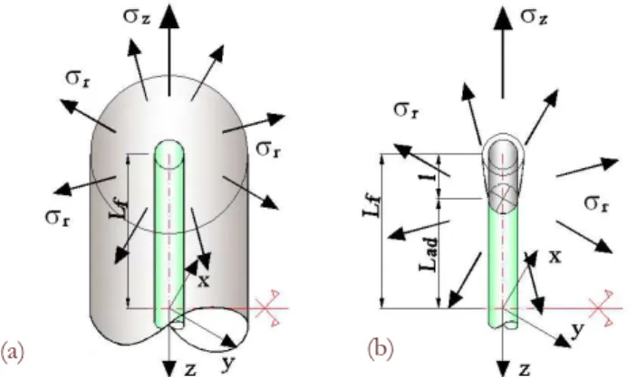
In fibre-reinforced composite materials, the fatigue assessment must take into account the matrix damage as well as the fibre-matrix interface. Since the local mechanical behaviour of a material containing a straight cylindrical fibre can be supposed to be transversally isotropic (Fig. 1a), the presence of a multiaxial stress state can be represented only by the stresses acting along the transversally isotropic axes, i.e. the radial axis and the axial one. According to such simplification, the multiaxial fatigue damage can be assessed by considering only the variability of such stresses.
Figure 1: (a) Cylindrical fibre surrounded by a cylindrical portion of matrix material; (b) partially detached fibre under radial and axial
stresses.
T
R. Brighenti et alii, Frattura ed Integrità Strutturale, 34 (2015) 59-68; DOI: 10.3221/IGF-ESIS.34.05
61
In the present paper, the damage taking place in the matrix and at the fibre-matrix interface is assumed to be non interacting, i.e. each of them can be assessed independently of the other. Moreover, the effect of the cyclic loading on the fibres is completely neglected.
Finally, as far as the matrix damage is concerned, the hypothesis of no crack formation and propagation in the bulk material is adopted, since the matrix is assumed to be ductile.
The multiaxial fatigue strength determination in the case of biaxial tension-torsion cyclic stress state is typically tackled by empirical approaches. In particular, for normal and shear cyclic stresses (with amplitudes a and a, respectively), a suitable relationship to identify the fatigue limit is [13]:
2 2
, 1 , 1
( a/ af ) ( a/ af ) 1 (1)
that can be determined once different values of biaxiality ratio, r a/ a, and phase shift angles have been fixed. Typically the stress amplitudes a, a are stresses measured in a particular plane, called critical plane.
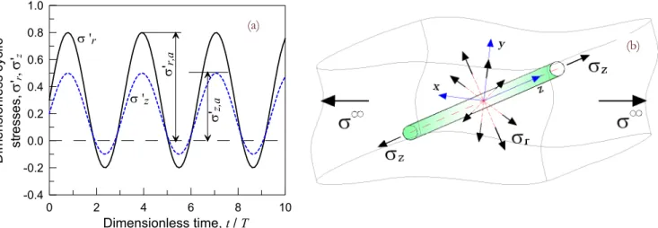
In the case of a reinforced material, the relevant cyclic stress amplitudes for the material interface can be assumed to be equal to r a, and z a, , i.e. the radial and the axial one. In Fig. 2a, the effective radial and axial (in phase) cyclic stresses amplitudes against time are shown. As can be noted, they are evaluated by neglecting the compressive portion of the cyclic stress diagrams, having assumed no damage when the material is compressed.
Equation (1) can be rewritten as follows (Fig.1a, b):
2 2
, , 1 , , 1
(z a/af ) (r a/af ) 1 (2)
which represents a circle in the z a, r a, plane (Fig. 3a) related to a given number of loading cycles to failure, Nf (Nf
is the number of loading cycles to failure for an uniaxial fatigue stress with the amplitude z a, or r a, ). Then, the normalized amplitudes are defined as follows:
, , 0, , , 0,
'z a z a/ ref, 'r a r a/ ref
(3)
with 0,ref = reference remote applied stress amplitude. The fatigue domain (2) can be rewritten through the above dimensionless stress amplitudes:
2 2
, 0, , 0,
, 1 , 1
' '
1
z a ref r a ref
af af
(4)
Such a biaxial fatigue stress domain can conveniently be applied to assess the damage degradation of the fibre-matrix interface layer, as is discussed later. In Fig. 2b, the radial and axial stresses for a generic fibre are represented in the case of a reinforced body under remote uniaxial cyclic stress.
A multiaxial fatigue-related parameter can be defined as follows:
, ( ) / ( )
f n f i
D N N N S (5)
where N is the current number of cycles characterising the stress state A and Nf n, (A) is the number of cycles to
failure under the uniaxial cyclic stress with amplitude Sn (r a2, z a2, ) ,1/2 n1, 2, 3,...., while its dimensionless amplitude
is 2 2 1/2
, ,
, 1 1
' ( ) , 1, 2, 3,....
n r a z a
af
S n
(Fig. 3a). The Wöhler curve (Fig. 3b) is generally a continuously decreasing
R. Brighenti et alii, Frattura ed Integrità Strutturale, 34 (2015) 59-68; DOI: 10.3221/IGF-ESIS.34.05
62
0 2 4 6 8 10
Dimensionless time, t / T
-0.4 -0.2 0.0 0.2 0.4 0.6 0.8 1.0
D
im
ens
io
nl
ess
cycl
ic
st
re
ss
es,
'r
,
'z
'r,a
'z,a
'r
'z
(a)
Figure 2: (a) Radial and axial cyclic dimensionless stresses vs time: definition of the effective stress amplitudes. (b) Scheme of the radial and axial matrix stresses near a cylindrical fibre.
Figure 3: (a) zr fatigue domains that identifies conventional fatigue life for a biaxial normal stress state. (b) The Wöhler curve
for a uniaxial cyclic stress history.
A generic mechanical parameter can be reduced by using the above damage variable as follows:
,0 ,
( ) 1 ( )
m m f n
P N P D N (6)
where Pm,0 is the initial value of the generic parameter, and P Nm( ) is its fatigue affected counterpart.
A suitable choice for modeling the matrix material under fatigue is to impose Pm0 Em0, where Em0 is the undamaged Young modulus, whereas its damaged counterpart is equal to the modulus E Nm( ), with
* *
0
( ) 1 ( , , )
m m cm
E N E D R N , where Dcm(*,R N*, )is the damage parameter obtained according to Eq. (5)
evaluated by assuming Sn 1,a max( r a, , z a, ), i.e. the equivalent uniaxial cyclic stress is identified by the maximum principal stress amplitude at the point under consideration.
FRACTURE MECHANICS APPROACH TO EXAMINE THE FIBRE DETACHMENT
he problem of the fibre-matrix detachment can be solved through a fracture mechanics approach. As a matter of fact, a partially debonded cylindrical fibre can be represented by a three-dimensional crack lying between two different materials [21, 22]. Such a problem is the spatial counterpart of the case related to an elastic bi-material
T
(a)
(b)
R. Brighenti et alii, Frattura ed Integrità Strutturale, 34 (2015) 59-68; DOI: 10.3221/IGF-ESIS.34.05
63
plane with an interface crack [23, 24]. According to the above assumption, the debonded zone corresponds to a 3D cylindrical crack lying between two different materials [21] (Fig. 1b).
Typically, the fibre-matrix stress interaction is analysed through the well-known shear lag model [25, 26], even if such an approach presents some limitations due to the inability of examining a complex stress state around the fibre.
The generic fibre, embedded in an elastic matrix (Fig 1b) under remote axial (z) and radial (r) stresses, is
characterised by an energetically equivalent SIF (along the circular crack front) defined as follows [27]:
2
2( ) ( ) ( ) 0
( ) 0
I r II r II z r
i
II z r
K K K
K
K
(7)
The generic dimensionless Mode M SIF (M I II, ), due to the remote stress w
(w r z, ), can be defined as
*Mw M( w ) / w
K K l with KMw KM(w )
. All the above SIFs K Ki, I(r ),KII(r ),KII(z )
are independent of
the angular co-ordinate due to the axial symmetry of the examined configuration.
An application of the above fracture mechanics problem concerns the dimensionless Mode II SIFs, K*IIz and K*IIr, due
to remote longitudinal (z
) and radial (r
) stresses. In Fig. 4, such quantities are represented for different values of the
material Young modulus ratio, Ef Em, and two values of the relative fibre detached length, l/Lf.
As can be noted, the SIF is an increasing function of the modulus ratio, while its value decreases by increasing the aspect ratio of the fibre, 2Lf f , i.e. the SIF is much more severe for short fibre-matrix detached length. The remote axial stress approximately produces only a Mode II SIF, whereas the remote radial positive stress is mainly responsible for both Mode I and mainly Mode II SIFs. The last cited stress-intensity factor arises due to the different elastic properties of the two joined materials.
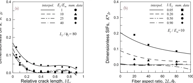
In Fig. 5, the dimensionless Mode I SIF due to a remote radial stress is displayed against the relative debonded length (Fig. 5a) and against the fibre aspect ratio (Fig. 5b). Such a SIF decreases by increasing the detached fibre length and by increasing the fibre aspect ratio, i.e. it is lower for longer fibres in the case of a given relative detached length.
The equivalent SIF at the fibre-matrix interface crack front is suitable to define the condition of unstable crack propagation (leading to a complete fibre-matrix separation), according to the energy-based Griffith approach:
2
plane stress
plane strain 1
i
i ic i
i E
K K E
ic
ic
G
G (8)
where Gic is the critical interface fracture energy, Kic is the corresponding fracture toughness, and Ei and i are the Young modulus and the Poisson ratio at the interface, respectively.
Multiaxial fibre-matrix interface damage under cyclic loading
The fracture mechanics approach to examine the fibre detachment has the benefit to allow us the use of the well-known crack growth approach to fatigue. As a matter of fact, if the total fatigue life is assumed to be the sum of the initiation and the propagation number of loading cycles, and the propagation stage prevails over the first one as in pre-cracked components or in presence of high stress concentration effects, the crack growth evaluation can lead to a proper expected fatigue life. In the present case, the pre-existing crack can be considered to be always present due to the unavoidable fibre-matrix detachment at the fibre extremities. Moreover, irrespective of the stress state in the material surrounding the fibre, the crack path is always well defined, since it corresponds to the outer fibre surface.
The crack propagation assessment can be performed through the debonding length rate law, or the crack growth velocity
cg
R. Brighenti et alii, Frattura ed Integrità Strutturale, 34 (2015) 59-68; DOI: 10.3221/IGF-ESIS.34.05
64
1 40
Young modulus ratio, Ef /Em 0.0 0.1 0.2 0.3 0.4 0.5 0.6 Dim ension less SIFs, K* II r
(a)
l/ Lf=0.1 num. data2Lf /f
20 40 80
5 10 15 20 25 30 35 l / Lf=0.7
1 40
Young modulus ratio, Ef /Em
0.0 0.2 0.4 0.6 0.8 1.0 1.2 1.4 D ime ns io nl es s SIFs , K* IIz num. data 2Lf/f
20 40 80
5 10 15 20 25 30 35
l / Lf=0.1
l / Lf=0.7
(b)
Figure 4: Dimensionless radial and longitudinal Mode II SIF, (a)KII r, and (b) KII z, , vs Young modulus ratio, Ef Em, for different
values of fibre aspect ratio, 2Lf f , and relative debonded length equal to 0.1 and 0.7.
0 0.2 0.4 0.6 0.8 1
Relative crack length, l/Lf
0.0 0.1 0.2 0.3 0.4 Dimensionless SIFs, K* Ir
(a)
Lf / f = 80 num. data interpol. Ef /Em
1 10 25 40
0 20 40 60 80 100
Fiber aspect ratio, 2Lf/f
0.0 0.1 0.2 0.3 0.4 Dimensio nle ss SIFs, K* Ir
(b)
Ef / Em=10 num. data interpol. l/Lf
0.05 0.20 0.50 0.90
Figure 5: Dimensionless radial and longitudinal Mode II SIF, (a) KII r, and (b) KII z, , vs Young modulus ratio, Ef Em , for different
values of fibre aspect ratio, 2Lf f , and relative debonded length equal to 0.1 and 0.7.
/ mi,
cg i i th i IC
v dl dNC K K K K (9)
In Eq. (9), C mi, i are the Paris constants of the interface, l is the debonded length (Fig. 1b), and Ki is the equivalent stress intensity factor range produced by the cyclic remote stresses. The above crack growth rate takes place in a thin weak layer placed between two different materials. Such a layer can be considered as a third material whose properties are themselves affected by the fatigue process. For the above reason, the interface crack propagates in such a degraded material, and a suitable evaluation of the damage can be done by using Eqs. (4) to (6). In the present study, the above biaxial damage evaluation is applied to the Paris constant Ci: C Ni( )Ci0/ (1Df i, ), where Ci0 is the undamaged initial constant value.
The critical detached length, lc, and the corresponding number of loading cycles, Nc, leading to such an ultimate condition can be evaluated as follows:
(b) (a)
R. Brighenti et alii, Frattura ed Integrità Strutturale, 34 (2015) 59-68; DOI: 10.3221/IGF-ESIS.34.05
65
0
( ) ,
c
i
N
m
c c i i
l N l
C K dN such that K li( ,c z, r)Kic (10)( ) ( ) / 0
i c
D N l N l
where the interface equivalent SIF is indicated as K li( , z, r) since it depends on the remote stress field and on the current debonded length for the given composite material. The current detached length can be used to quantify a debonding-related damage Di which is assumed to be equal to the ratio between the current debonded length l and the
critical length lc corresponding to the condition of unstable crack propagation, that is, to the condition of complete fibre detachment from the matrix material for which the damage is complete, i.e. D Ni( c) 1 .
On the other hand, it has been shown that K li( , z, r) is a decreasing function of l [27], i.e. the SIF decreases as the detached length increases, and the critical condition cannot be reached during crack propagation. The fibre-matrix debonding-related damage Di can also be defined as follows:
0Di l/Lf 1 (11)
and measures the effectiveness of the fibre in the bearing mechanism of the composite material.
On the other hand, the detachment phenomenon could synthetically be quantified also through a so-called sliding scalar
function (s mf ) [26] (and the interface damage can thus be measured as follows: 1 ( )
m
i f
D s ). The sliding scalar
function can approximately be estimated as follows: ( m) ( ) /
f f f
s L l L .
By means of the current debonded fibre length determined above, the sliding function parameter s(εmf )f /mf (given by the ratio of the fibre strain to matrix strain measured in the fibre direction) can be evaluated, and the tangent elastic tensor 'Ceq of the homogenized material can be obtained [27]:
( )
' ' ' ( ) ( ) ( )
m f
m m
eq m f f f m
f ds ε
E s ε p p d
dε
C C F F (12)
where , are the fibre and matrix volume fractions, respectively; ' ,Cm E'f are the tangent elastic tensor of the matrix
material and the fibre tangent elastic modulus, respectively; p( ) and p( ) are the probability distribution functions
describing the fibres arrangement in 3D space; F is the second-order tensor defined as follows: F k k, where k is the unit vector identifying the fibre axis [27]. Such a homogenization procedure is carried out as the fibre progressively detaches due to fatigue loading.
NUMERICAL SIMULATIONS
ow the fatigue behaviour of a 13% glass fibre-reinforced polyamide specimen (with fibres oriented parallel, i.e. with 0º, or inclined by an angle 30º with respect to the load direction) under constant amplitude uniaxial cyclic stress is examined [28].
The materials constituting the specimen are characterised by the following mechanical properties: matrix Young modulus 2.2
m
E GPa, Poisson’s ratio m 0.4, fibres Young modulus Ef 72.45GPa, Poisson’s ratio f 0.23, fibre diameter
equal to f 10m and length 2 5.5 10 4 f
L m. The Paris constants of the interface are 8.7 10 9 i
C and mi 13.9
(dl dN/ in mm/cycle, Ki in MPa m ), i.e. those of the matrix material, whereas the Wöhler constants are
0 10MPa
, 6
0 2 10
N (fatigue limit and corresponding conventional number of loading cycles), B0.133.
R. Brighenti et alii, Frattura ed Integrità Strutturale, 34 (2015) 59-68; DOI: 10.3221/IGF-ESIS.34.05
66
(a)
1E+003 1E+004 1E+005 1E+006 1E+007
Number of cycles to failure, Nf
25 30 35 40 45 50 55 60 65 70 Stress ampl itude , * (MP a)
(b)
f =13%
Exp. res. [28] FEM, present res. 0º 30º
Figure 6: (a) Geometrical dimensions, expressed in (mm), and FEM model of the specimen; (b) the Wöhler curves of the glass
fibre-reinforced polyamide specimen: experimental [28] and present results.
1E+003 1E+004 1E+005 1E+006 1E+007
Number of cycles to failure, Nf
0.0 0.2 0.4 0.6 0.8 1.0 Mat
rix damage pa
ramete r, DE (-) 0.000 0.010 0.020 M atr ix s tra in , m (-)
(a)
* = 45 MPa
0º 30º
DE m
1E+003 1E+004 1E+005 1E+006 1E+007
Number of cycles to failure, Nf
0.0 0.2 0.4 0.6 0.8 1.0 Di mens ion le ss de bon de d l en gth , (-) 0.0 0.2 0.4 0.6 0.8 1.0 S lid in g fu nc tio n, s (-)
(b)
* = 45 MPa
0º 30º
s
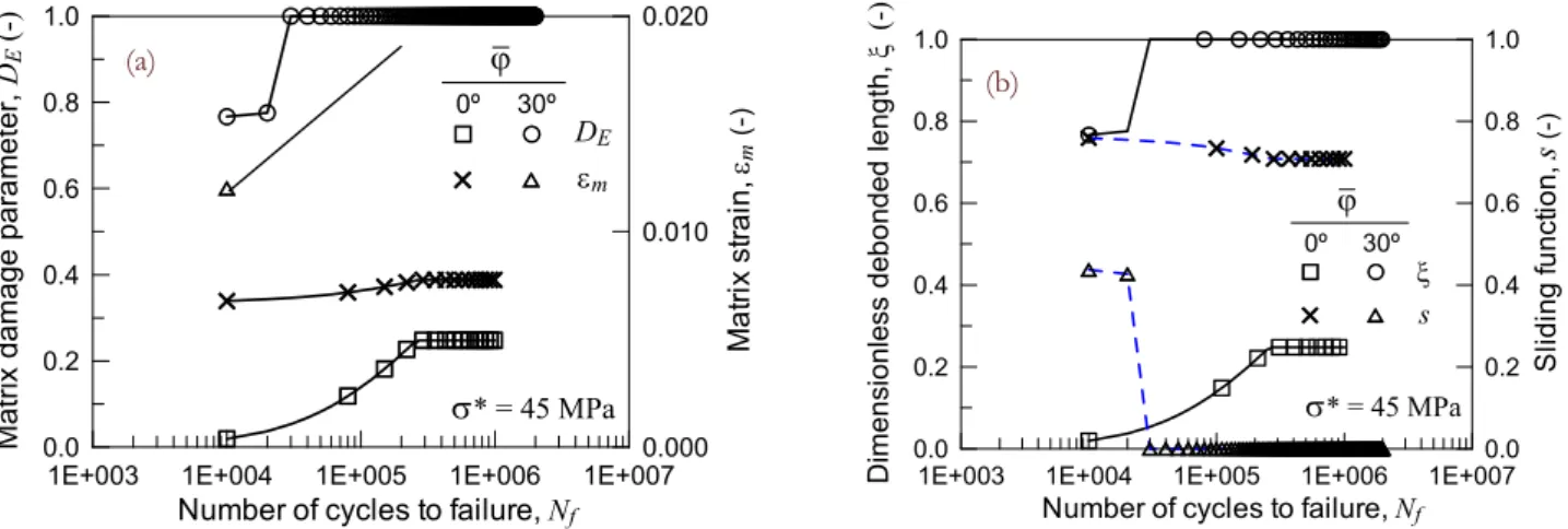
Figure 7: (a) Damage and strain evolution in the matrix (at point P) vs the number of stress cycles; (b) dimensionless fibre debonded
length , and sliding parameter s, (at point P) vs the number of stress cycles.
The fatigue failure of the material is assumed to occur when the maximum matrix strain reaches a given admissible value that has been assumed equal to 10% in the present case.
In Figure 6, the experimental S-N curves for the two considered fibre arrangements are reported. It can be observed that the fibres aligned with the fatigue loading direction are most effective and, for a given stress amplitude, a greater number of loading cycles can be reached before the material failure for such fibre arrangement. The numerical evaluation of the number of loading cycles to failure is in accordance with the above observation, providing results that are in acceptable agreement with the experimental outcomes [28].
In Figure 7a, the damage parameter DE, applied to the Young modulus of the matrix, is plotted together with the matrix
strain against the number of loading cycles.
In Figure 7b, the dimensionless fibre debonded length and the sliding function are plotted against the number of loading cycles N: the function (s N) decreases with N, indicating a decreasing of the fibre capability to carry the applied load transferred from the matrix as the number of cycles increases. As a consequence, the stress fraction sustained by the matrix increases with N (being constant the maximum applied stress during fatigue), and the damage in the bulk material increases.
(b)
(a)
R. Brighenti et alii, Frattura ed Integrità Strutturale, 34 (2015) 59-68; DOI: 10.3221/IGF-ESIS.34.05
67
In the case of fibres aligned with the loading direction ( 0º), the sliding parameter stabilises after a certain number of loading cycles, and the maximum strain in the matrix appears to increase very slightly with N.
CONCLUSIONS
n the present paper, a micromechanical model for the evaluation of the unixial or multiaxial fatigue behaviour of fibre-reinforced structural elements having equi-oriented or randomly distributed fibres has been presented. The effective spatial arrangement of the fibres is statistically taken into account by adopting a Gaussian-like distribution function, whereas the mechanical effect of the fibre on the composite is accounted for by a homogenization approach aimed at obtaining the macroscopic elastic constants of the material. The fatigue fibre-matrix debonding is evaluated by using a fracture mechanics approach. Matrix damage under fatigue is determined by considering the local anisotropy of the material due to the fibres, i.e. a multiaxial fatigue criterion for constant amplitude loading is proposed. Finally, the micromechanical model is employed to assess the fatigue behaviour of a representative unidirectional-reinforced polymeric samples, providing results in line with the experimental data.
REFERENCES
[1] Jones, RMA., Mechanics of Composite Materials, second ed., Taylor & Francis Group, (1999).
[2] Cheng, QG., Fiber Reinforced Composites. Nova Science Publishers, Inc., Hauppauge, NY, (2012). ISBN: 978-1-62081-559-5.
[3] Brighenti, R., Numerical modelling of the fatigue behaviour of fiber reinforced composites. Comp Part B, 35(3) (2004) 197–210. DOI: 10.1016/j.compositesb.2003.10.003
[4] Guo, LP., Carpinteri, A., Spagnoli, A., Sun W., Experimental and numerical investigations on fatigue damage propagation and life prediction of high-performance concrete containing reactive mineral admixtures. J Fat., 32 (2010) 227–37. DOI: 10.1016/j.ijfatigue.2009.05.009
[5] Pook, LP., The Role of Crack Growth in Metal Fatigue, Metals Society, London, UK, (1983).
[6] Carpinteri, A., (Ed.) Handbook of Fatigue Crack Propagation in Metallic Structures, Elsevier Science BV, Amsterdam, (1994).
[7] Pook, LP., Crack Paths, WIT Press, Southampton, UK (2002).
[8] Wöhler, A., Versucheüber die festiykeit eisenbahnwagenuchsen, Z Bauwesen, 10 (1860). [9] Basquin, OH., The exponential law of endurance tests, Proc ASTM, 10 (1910) 625–630.
[10]Paris, P., Erdogan, F., A critical analysis of crack propagation laws, J. Basic Engng, Trans Am Soc Mech Eng, 85 (1963) 528–534. DOI: 10.1115/1.3656900
[11]Brown, MW., Miller, KJ., A theory for fatigue failure under multiaxial stress-strain condition, Proc Inst Mech Engrs, 187 (1973) 745–755. DOI: 10.1243/PIME_PROC_1973_187_161_02
[12]Carpinteri, A., Macha, E., Brighenti, R., Spagnoli, A., Expected principal stress directions for multiaxial random loading - Part I: Theoretical aspects of the weight function method, Int. J. Fat., 21 (1999) 83–88. DOI: 10.1016/S0142-1123(98)00046-2
[13]Carpinteri, A., Spagnoli, A., Multiaxial high-cycle fatigue criterion for hard metals, Int. J. Fat., 23 (2001) 135–145. DOI: 10.1016/S0142-1123(00)00075-X
[14]Sines, G., Failure of materials under combined repeated stresses with superimposed static stresses, Tech. Rep. Technical note 3495, Nat. Adv. Coun. Aeronaut., Washington D.C., USA (1955).
[15]Cristofori, A., Susmel, L., Tovo, R., A stress invariant based criterion to estimate fatigue damage under multiaxial loading, Int. J. Fat., 30 (2007) 1646–1658. DOI: 10.1016/j.ijfatigue.2007.11.006
[16]Smith, K.N., Watson, P., Topper, TH., A stress-strain function for the fatigue of metals, J. Mater JMLSA, 5 (1970) 767–778.
[17]Macha, E., Sonsino, CM., Energy criteria of multiaxial fatigue failure, Fat. Fract. Engng Mater. Struct., 22 (1999) 1053–1070. DOI: 10.1046/j.1460-2695.1999.00220.x
[18]Ottosen, N.S., Stenstrom, R., Ristinmaa, M., Continuum approach to high-cycle fatigue modelling, Int. J. Fat., 30 (2008) 996–1006. DOI: 10.1016/j.ijfatigue.2007.08.009
[19]Brighenti, R., Carpinteri, A., A notch multiaxial-fatigue approach based on damage mechanics, Int. J. Fat., 39 (2012) 122-133. DOI: 10.1016/j.ijfatigue.2011.02.003
R. Brighenti et alii, Frattura ed Integrità Strutturale, 34 (2015) 59-68; DOI: 10.3221/IGF-ESIS.34.05
68
[20]Carpinteri, A., Spagnoli, A., Vantatori, S., An approach to size effect in fatigue of metals using fractal theories, Fat. Fract. Engng Mater. Struct., 25 (2002) 619–627. DOI: 10.1046/j.1460-2695.2002.00506.x
[21]Wüthrich, C., Stress intensity factors for cylindrical cracks in long cylinders, Engng Fract Mech., 13 (1980) 987–990. DOI: 10.1016/0013-7944(80)90028-4
[22]Zbib, H.M., Hirth, J.P., Demir, I., The stress intensity factor of cylindrical cracks, Int J Engng Sci., 33 (1995) 247–253. DOI: 10.1016/0020-7225(94)E0051-J
[23]Rice, JC., Elastic fracture mechanics concepts for interfacial cracks, J Appl Mech., 55 (1988) 98–103. DOI: 10.1115/1.3173668
[24]Hutchinson, J.W., Mear, M.E., Rice, J.C., Crack paralleling an interface between dissimilar materials, J Appl Mech., 54 (1987) 828–832. DOI: 10.1115/1.3173124
[25]Cox, H.L., The elasticity and strength of paper and other fibrous materials, British Journal of Applied Physics, 3 (1952) 72–79. DOI: 10.1088/0508-3443/3/3/302
[26]Brighenti, R., Scorza, D., A micro-mechanical model for statistically unidirectional and randomly distributed fibre-reinforced solids, Mathem Mech. Sol., 18 (2012) 876–893. DOI: 10.1177/1081286512454447
[27]Brighenti, R., Carpinteri, A., Scorza, D., Fracture mechanics approach for a partially debonded cylindrical fibre, Compos. Part B: Engineering, 53 (2013) 169-178. DOI: 10.1016/j.compositesb.2013.03.042