1.University of Stavanger – Faculty of Science and Technology – Department of Mechanical and Structural Engineering and Materials Science – Stavanger – Norway.
Correspondence author: Dimitrios G. Pavlou | University of Stavanger – Faculty of Science and Technology – Department of Mechanical and Structural Engineering and Materials Science | Kjell Arholmsgate, 41 | NO-4036 – Stavanger – Norway | E-mail: [email protected]
Received: Oct. 03, 2016 | Accepted: Jul. 07, 2017
Section Editor:Valder Steffen Jr
ABSTRACT: The technique of retarding the growth of fatigue cracks by drilling holes on the crack tip is well known. Most of the research works on this subject are limited to fatigue cracks subjected to mode I loading conditions. In the present work the fatigue crack growth retardation by stop-holes of cracks under mode I+II loading is investigated. The proposed approximate solution is based on the implementation of a mixed-mode fatigue crack growth model and a multiaxial high cycle fatigue criterion. Numerical results for mode I+II fatigue crack growth retardation on Al-2024 thin plate are derived and the effect of the crack inclination angle, as well as the diameter of the stop-hole, are discussed and commented.
KEYWORDS: Structural integrity, Stop-holes, Mixed-mode loading, Multiaxial fatigue, Fatigue crack growth retardation.
INTRODUCTION
Since the drilling of a hole on the crack tip transforms the stress singularity of the crack tip to a notch, reducing thus the values of the stresses, it is a widely used technique for simple and economic repair method. Estimation of the delay (in terms of loading
cycles) of the fatigue crack growth has been performed (e.g. Wu et al. 2010; Makabe et al. 2009; Ayatollahi et al. 2014; Fanni
et al. 2015) to improve the structural integrity of cracked structures. However, most of the existing studies are focusing on cracks subjected to pure mode-I loading (Fig. 1), and few studies are analyzing cracks under pure mode-II loading (e.g. Ayatollahi et al. 2014). Since the structural integrity of aerospace structures is of vital importance for the aerospace industry (Mello Jr. and
Mattos 2009; Mello Jr. et al. 2009; Mattos et al. 2009), the knowledge of the fatigue crack growth retardation due to stop-holes is
important to improve the inspection plans.
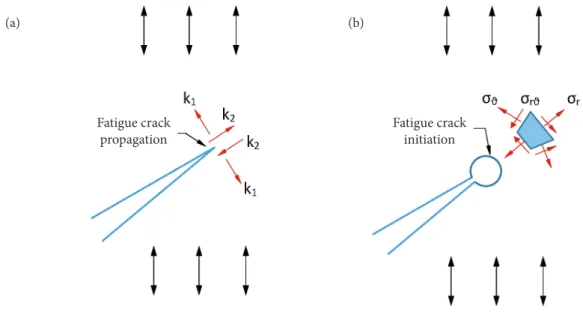
Fatigue crack propagation is governed by the amplitude of the stress intensity factors (Fig. 1a). For any crack subjected to cyclic loading, fracture mechanics rules are used for fatigue crack propagation prediction. However, when a hole is drilled on
the crack tip (Fig. 1b) the crack tip singularity is eliminated. Th e surface on the perimeter of the hole is smooth, crack initiation
mechanisms take place, and the multiaxial stress state (instead of the stress intensity factor) is the driving force for fatigue damage
accumulation (multiaxial fatigue). Th en, crack initiation models (e.g. Pavlou 2018; Rege and Pavlou 2017) should be applied to
estimate delay cycles.
Mode I+II Fatigue Crack Growth Delay by
Stop-Holes
Dimitrios G. Pavlou1
Pavlou DG (2018) Mode I+II fatigue crack growth delay by stop-holes. J Aerosp Tecnol Manag, 10: e1518, doi: 10.5028/ jatm.v10.808
How to cite
Figure 1. (a) Crack subjected to cyclic loading, (b) A hole drilled on the crack tip transforms the crack singularity to a smooth surface.
However, for cracks subjected to mode I+II loading (Fig. 2), the solution is more complicated due to the following reasons:
• The crack growth follows a zig-zag path. Therefore, the direction of crack deflection ϑ* due to an inclined crack with
inclination angle β should be initially calculated.
• Unlike the mode-I cracks, the stress state of a point A on the perimeter of the stop-hole is multiaxial (Fig. 2).
• The calculation of the k1 and k2 local stress intensity factors is not an easy task.
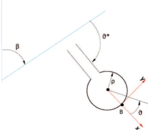
Figure 2. A mode I+II crack repaired by a stop-hole.
Therefore, the computation of the crack initiation period for the point A (Fig. 2) is based upon the computation of the stresses
σxx, σyy, τxy. The values of these stresses depend on the angles β and ϑ*. For multiaxial fatigue life prediction, several effective criteria
have been published (Fatemi and Shamsaei 2011; Carpinteri et al. 2011; Mamiya et al. 2009; Liu and Mahadevan 2005; Lee et al.
2007). Among them, the criterion of the critical plane and the criterion of the equivalent stress are widely used. In the present work, the criterion of the equivalent stress is adopted due to its simplicity.
Fatigue crack initiation Fatigue crack
propagation
Figure 3. An inclined crack (with inclination angle β) propagates in a direction ϑ* yielding minimum potential energy. Regarding the crack propagation direction of cracks subjected to mode I+II loading, numerous criteria (models) have been published. The models can be classified in four categories: (a) stress-based criteria, (b) strain-based criteria, (c) crack tip displacement criteria, (d) energy-based criteria. The most known stress-based criterion is the Maximum Tangential Stress (MTS) criterion proposed by Erdogan and Sih (1963). This criterion assumes that crack propagates along the radial direction on which
the stress σϑ becomes maximum. Representative strain-based criterion is the maximum tangential strain criterion proposed by
Chambers et al. (1991). According to this criterion, the maximum elastic tangential strain near the crack tip controls the
mixed-mode crack propagation direction. A criterion proposed by Li (1989) assumes that mixed-mixed-mode crack propagates along the vector crack tip displacement (CTD). The main energy based criteria, namely the J-criterion, the T-criterion, and the S-criterion, have been proposed by Helen and Blackburn (1975), Theocaris and Andrianopoulos (1982), and Sih (1974), respectively. The J-criterion states that a mixed-mode crack propagates along the direction of the vector J. According to the T-criterion, the crack propagates along the maximum dilatational strain energy density direction. The S-criterion assumes that mixed mode crack propagates in a direction along with S-factor possesses a relative minimum. All the above criteria are based on energy density or stress or strain distribution before the event of crack propagation.
For the prediction of the direction ϑ* of the propagation of a crack under mode I+II loading conditions, a model based on the
principle of minimum potential energy, developed recently (Pavlou2015a; Pavlou 2015b; Pavlou et al. 2004; Pavlou et al. 2003), is
used in the present study. According to this model, an inclined crack (with inclination angle β) is going to propagate in a direction ϑ* (Fig. 2), which yields minimum potential energy to the material (Fig. 3).
Even though the principle of the minimum potential energy was proposed many decades ago, its implementation on Fracture Mechanics was limited to take the derivative with respect to the crack length (∂∏ / ∂α) in order to derive the formula for the fracture
toughness. Pavlou 2015a, Pavlou 2015b, and Pavlou et al. 2004 proposed the condition of minimization of the potential energy
with respect to the crack propagation angle ∂∏ / ∂ϑ for the direction prediction of mode I+II fatigue crack growth. Verification
on experimental results (Pavlou et al. 2004) has indicated that the predictions have been accurate.
Due to the mode I+II conditions, the stresses in the vicinity of the perimeter of a stop-hole located on the branched crack (in
direction ϑ*) are multiaxial. Th e analytic calculation of these stresses is a challenge, therefore, numerical analysis by using fi nite
or boundary elements is the best practice. For the sake of simplicity, an analytic expression (Tada et al. 2000) valid for the points
on the vicinity of the perimeter of the hole near the direction of the crack will be adopted. Th en, the equivalent multiaxial fatigue
criterion (Lee et al. 2012) will be used to calculate the number of cycles yielding fatigue crack initiation.
MIXED MODE FATIGUE CRACK GROWTH
As it has already been mentioned, the direction of the propagation of a fatigue crack under mode I+II conditions can be predicted by the Eq. 1:
where: ƒ(ϑ) is a function expressing the potential energy variation versus the angle ϑ of the direction of possible crack propagation
(Fig. 3). Taking into account the references (Pavlou 2015a; Pavlou 2015b; Pavlou et al. 2004), the function to be minimized is Eq. 2:
where::
(1)
(2)
(3)
(6) (4)
(7) (5)
(8)
(9)
(10)
(11)
λ1 = 0.0000101419
Taking into account Eqs. 1 to 11, the crack propagation direction ϑ* versus β (Fig. 3) can be obtained (Pavlou 2015a; Pavlou 2015b) by the Eq. 12:
where the angle β should be placed in degrees.
STRESS STATE DUE TO A STOP-HOLE IN A BRANCHED CRACK
Th e stress state on a material element along the perimeter of a stop hole placed on the branch of a mode I+II fatigue crack
(Fig. 2) is multiaxial. Analytic calculation of the stresses σxx, σyy, τxy is not an easy task, therefore, implementation of numerical
methods (e.g. FEM or BEM) is the best practice. However, approximate formulae can be found in Tada et al. 2000, providing the
stresses for small ϑ and r ≈ ρ (Fig. 4).
Figure 4. Topology of a hole placed on the branch of a mode I+II crack with inclination angle β.
According to Tada et al. (2000), the stresses on the point B in Fig. 4 can be obtained by the Eqs. 13 to 15:
MULTIAXIAL FATIGUE MODEL
Taking into account the above stress state, a multiaxial fatigue crack initiation model should be used in order to estimate the delay (in terms of number of cycles) for further crack growth. Among the multiaxial fatigue crack initiation models, the equivalent
(12)
(13)
(14)
(15)
stress model (Lee et al. 2012) is adopted due to its simplicity. According to this criterion, the equivalent stress is the driving force
for the crack initiation. Th e Eq. 16 takes into account the equivalent stress amplitude (Eq. 17)
and the equivalent mean stress (Eq. 18)
Th e parameter aVM refl ects the eff ect of the mean stress (Eq. 19)
where: σE,R = –1 is the fatigue endurance limit for fatigue loading with R = σmin / σmax = –1, i.e., σm = 0; and σE,R≠ –1 is the fatigue
endurance limit for any loading with R ≠ –1, i.e., σm≠ 0. Th e value of σE,R = –1 can be obtained by a standard S-N curve (Fig. 5).
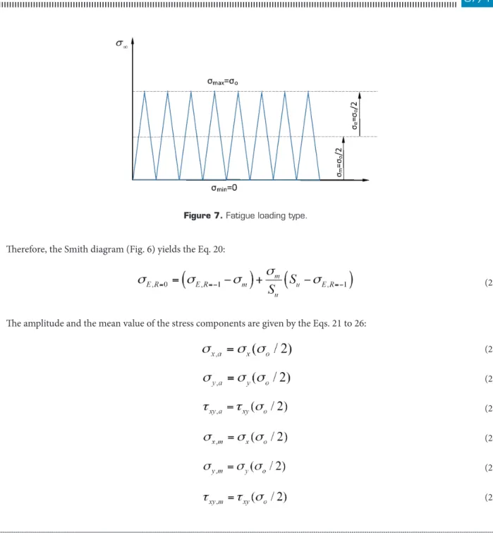
For fatigue loading with σm≠ 0, the well-known Smith diagram (Fig. 6) should be used to calculate the value of σE,R≠ –1. In
the present study, a fatigue loading with σmin = 0 (i.e. R = 0) or σm = σa = σo/ 2 is considered (Fig. 7).
Figure 6. Smith diagram.
Figure 5. Schematic representation of an S-N curve.
(16)
(17)
(18)
(19)
Figure 7. Fatigue loading type.
Th erefore, the Smith diagram (Fig. 6) yields the Eq. 20:
Th e amplitude and the mean value of the stress components are given by the Eqs. 21 to 26:
RETARDATION OF THE FATIGUE CRACK GROWTH
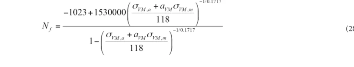
Since the above stresses (Eqs. 21 to 26) are the consequence of the hole, the equivalent stress σeq given by Eq. (16) should be
used to estimate the number of cycles causing crack initiation. To this end, a standard S-N curve can be used. For the well-known
alloy Al-2024, an analytic expression (Eq. 27) (Siriwardane et al. 2010) can be adopted:
If we replace the uniaxial stress amplitude S by the equivalent one, given by Eq. 16, the Eq. 28 for calculating the required
cycles to cause fatigue crack initiation can be obtained:
(20)
(21)
(23)
(25) (22)
(24)
(26)
NUMERICAL IMPLEMENTATION OF THE METHODOLOGY
A thin Al-2024 plate containing an inclined crack of 2.0 mm is subjected to fatigue loading with σa = 90 MPa and σm = 90 MPa.
A stop-hole is considered to be placed on the branch (oriented in an angle ϑ*) closed to the crack tip of the crack α. Th e proposed
methodology is applied to estimate the required number of cycles causing crack initiation on a point located on the perimeter of the stop-hole. In order to investigate the eff ect of the orientation angle β and the stop-hole diameter, the methodology is applied for seven values of β, namely β = 21.0, 30.4, 39.8, 49.1, 58.5, 64.9, 71.0 deg., and three values of the radius of the stop-hole, namely
ρ = 2.5, 5.0, 7.5 mm. Th e results of the above example are demonstrated in Fig. 8.
Figure 8. Delay of fatigue crack growth versus crack inclination angle for three values of the radius of the stop-hole.
It should be mentioned that the number of delay cycles depends on the angle ϑ*, which is, in turn, related to β. Since the angle β is initially observed on an engineering structure (ϑ* is a consequence of the angle β and the loading conditions), the Fig. 8
demonstrates the delay of fatigue crack growth versus β. Th is fi gure indicates that high β values tending to 90 deg. (mode I) yield
a rapid decrease of the delay of the crack initiation. Th erefore, the eff ectiveness of stop holes is better when we drill them in the
early stages of the mixed mode fatigue crack propagation, before the transformation of the mode I+II crack to pure mode I crack. Furthermore, as it is expected, larger stop-hole diameter causes much more retardation to the crack initiation.
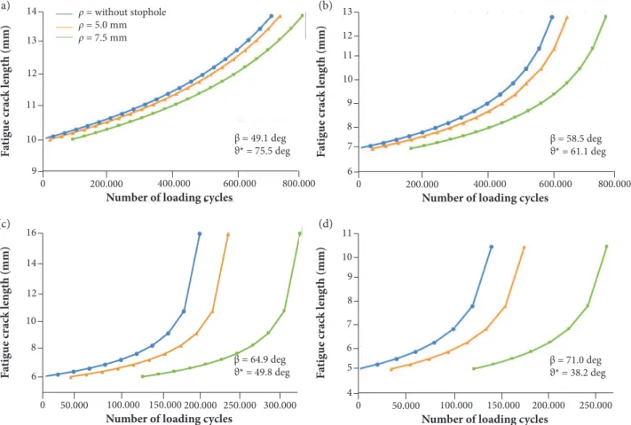
Th e fatigue crack length (along the path oriented in angle ϑ*) versus the number of cycles for β = 49.1, 58.5, 64.9, 71.0 deg.
is demonstrated in Figs. 9a, 9b, 9c, 9d for two values of stop-hole radius ρ = 5.0 mm and ρ = 7.5 mm. Th is fi gure indicates that
small values of angle β yield slow crack growth rate, therefore longer fatigue life. On the other hand, larger stop-hole diameters are more eff ective than small ones.
Th e orientation of the crack plane in the crack growth based on Figs. 9a, 9b, 9c, 9d is γ = ϑ* + β – 90. Th erefore, γ = 34.6o in
Fig. 9a, γ = 29.6o in Fig. 9b, γ = 24.7o in Fig. 9c, and γ = 19.2o in Fig. 9d. Taking into account the results of Fig. 9, the number of
delay cycles with respect to the crack growth curve without hole for a crack length α = 10 mm is shown in Table 1. From this table
no large diff erences are observed. Th e number of delay cycles between γ = 19.2o and γ = 24.7o is very small. A bigger diff erence
takes place between γ = 26.9o and γ = 34.6o. Since the diff erences in the orientation of the crack plane are not so large and the
shear eff ect does not appear to change signifi cantly, the results of the Table 1 seem to be reasonable.
(28) 20 0 200,000 400,000 500,000 800,000
30 40 50 60 70
Crack inclination angle β (deg)
D el ay o f f at ig u e cr ack g ro w th (c ycl es)
p = 7.5 mm
p = 7.5 mm
Figure 9. Crack length versus number of cycles for (a) β = 49.1 deg., (b) β = 58.5 deg., (c) β = 64.9 deg., and (d) β = 71.0 deg.
CONCLUDING REMARKS
• The fatigue crack growth delay of mixed mode cracks due to stope-holes has been investigated.
• A methodology based on a mixed mode fatigue crack growth model and a multiaxial fatigue criterion is proposed.
• Implementation of the methodology on a thin Al-2024 plate containing a mode I+II crack has been performed.
• The results indicated that the fatigue crack growth delay is more effective for cracks with small inclination angle
with respect to the loading direction. The mixed-mode fatigue crack growth rate of the deflected crack is smaller for cracks with small inclination angle. Large stop-holes cause much better extension of the fatigue life than small stop-holes.
Table 1. Number of delay cycles versus γ.
Orientation of the crack plane γ (deg.) Number of delay cycles for ρ = 7.5 mm Number of delay cycles for ρ = 5.0 mm
34.6o 268,530 72,683
29.6o 165,222 40,462
24.7o 127,339 36,212
19.2o 121,427 34,588
0 4 5 6 7 8 9 10 11
50.000 100.000 150.000 200.000 250.000
Number of loading cycles
F at ig u e cr ack l en g th (mm)
ρ = without stophole ρ = 5.0 mm ρ = 7.5 mm
β = 71.0 deg ϑ* = 38.2 deg 0 6 7 8 9 10 11 12 13
200.000 400.000 600.000 800.000
Number of loading cycles
F at ig u e cr ack l en g th (mm)
β = 58.5 deg ϑ* = 61.1 deg
0 6 8 10 12 14 16
50.000 100.000 150.000 200.000 250.000 300.000
Number of loading cycles
F at ig u e cr ack l en g th (mm)
β = 64.9 deg ϑ* = 49.8 deg 0 9 10 11 12 13 14
200.000 400.000 600.000 800.000
Number of loading cycles
F at ig u e cr ack l en g th (mm)
β = 49.1 deg ϑ* = 75.5 deg
(a)
(c)
(b)
REFERENCES
Ayatollahi MR, Razavi SMJ, Chamani HR (2014) Fatigue life extension by crack repair using stop-hole technique under pure mode-I and pure mode-II loading conditions. Procedia Engineering 74:18-21. doi: 10.1016/j.proeng.2014.06.216
Carpinteri A, Spagnoli A, Vantadori S (2011) Multiaxial fatigue assessment using a simplified critical plane-based criterion. International Journal of Fatigue 33(8):969-976. doi: 10.1016/j.ijfatigue.2011.01.004
Chambers AC, Hyde TH, Webster JJ (1991) Mixed mode fatigue crack growth at 550oC under plane stress conditions in jethete M152. Engineering Fracture Mechanics 39:603-619.
Erdogan F, Sih GC (1963) On the crack extension in plates under plane loading and transverse shear. J. Bas. Engng, ASME Trans. 85(4):519-525. doi: 10.1115/1.3656897
Fanni M, Fouda N, Shabara MAN, Awad M (2015) New crack stop hole shape using structural optimizing technique. Ain Shams Engineering Journal 6(3):987-999. doi: 10.1016/j.asej.2015.02.010
Fatemi A, Shamsaei N (2011) Multiaxial fatigue: an overview and some approximation models for life estimation. International Journal of Fatigue 33(8):948-958. doi: 10.1016/j.ijfatigue.2011.01.003
Helen TK, Blackburn WS (1975) The calculation of stress intensity factors for combined tensile and shear loading. International Journal of Fracture 11(4):605-617. doi: 10.1007/BF00116368
Lee YL, Barkey ME, Kang HT (2012) Metal fatigue analysis handbook. Oxford: Butterworth-Heinemann (imprint of Elsevier).
Lee YL, Tjhung T, Jordan A (2007) A life prediction model for welded joints under multiaxial variable amplitude loading histories. International Journal of Fatigue 29(6):1162-1173. doi: 10.1016/j.ijfatigue.2006.09.014
Li C (1989) Vector CTD criterion applied to mixed mode fatigue crack growth. Fatigue and Fracture of Engineering Materials and Structures 12(1):59-65. doi: 10.1111/j.1460-2695.1989.tb00508.x
Liu Y, Mahadevan S (2005) Multiaxial high-cycle fatigue criterion and life prediction for metals. International Journal of Fatigue 27(7):790-800. doi: 10.1016/j.ijfatigue.2005.01.003
Makabe C, Murdani A, Kuniyoshi K, Irei Y, Saimoto A (2009) Crack-growth arrest by redirecting crack growth by drilling stop holes and inserting pins into them. Engineering Failure Analysis 16(1):475-483. doi: 10.1016/j.engfailanal.2008.06.009
Mamiya EN, Araújo JA, Castro FC (2009) Prismatic hull: a new measure of shear stress amplitude in multiaxial high cycle fatigue. International Journal of Fatigue 31(7):1144-1153. doi: 10.1016/j.ijfatigue.2008.12.010
Mattos DFV, Mello Jr. AWS, Ribeiro FN (2009) F-5M DTA program. Journal of Aerospace Technology and Management 1(1):113-120. doi: 10.5028/jatm.2009.0101113120
Mello Jr. AWS, Mattos DFV (2009) Reliability prediction for structures under cyclic loads and recurring inspections. Journal of Aerospace Technology and Management 1(2):201-209. doi: 10.5028/jatm.2009.0102201209
Mello Jr. AWS, Garcia AN, Ribeiro FN, Mattos DFV (2009) Brazilian Air Force aircraft structural integrity program: an overview. Journal of Aerospace Technology and Management 1(1):107-111. doi: 10.5028/jatm.2009.0101107111
Pavlou DG, Labeas GN, Vlachakis NV, Pavlou FG (2003) Fatigue crack propagation trajectories under mixed-mode cyclic loading. Engineering Structures 25(7):869-875. doi: 10.1016/S0141-0296(03)00018-X
Pavlou DG, Vlachakis NV, Pavlou MG, Vlachakis VN (2004) Estimation of fatigue crack growth retardation due to crack branching. Computational Materials Science 29(4):446-452. doi: 10.1016/j.commatsci.2003.12.003
Pavlou DG (2015a) Fatigue crack deflection-induced retardation based on the principle of the minimum potential energy. International Review of Mechanical Engineering 9(3):324-330. doi: 10.15866/ireme.v9i3.6153
Pavlou DG (2015b) Simulation of Mode I+II crack propagation trajectories under static loading. International Review of Modeling and Simulations 8(4):499-504. doi: 10.15866/iremos.v8i4.7128
Pavlou DG (2018) The theory of the S-N fatigue damage envelope: generalization of linear, double-linear, and non-linear fatigue damage models. International Journal of Fatigue 110:204-214. doi: 10.1016/j.ijfatigue.2018.01.023
Qian J, Fatemi A (1996) Mixed mode fatigue crack growth: A literature survey. Engineering Fracture Mechanics 55(6):969-990. doi: 10.1016/S0013-7944(96)00071-9
Rege K, Pavlou DG (2017) A one-parameter nonlinear fatigue damage accumulation model. International Journal of Fatigue 98:234-246. doi: 10.1016/j.ijfatigue.2017.01.039
Siriwardane SASC, Ohga M, Dissanayake PBR, Kaita T (2010) Structural appraisal-based different approach to estimate the remaining fatigue life of railway bridges. Structural Health Monitoring 9(4):323-339. doi: 10.1177/1475921710361320
Tada H, Paris PC, Irwin GR (2000) The stress analysis of cracks handbook. London: Professional Engineering Publishing.
Theocaris PS, Andrianopoulos NP (1982) The T-criterion applied to ductile fracture. International Journal of Fracture 20(4):125-130. doi: 10.1007/BF01130617