On the evolution and comparison of
multiaxial fatigue criteria
B. Kenmeugne#1, B. D. Soh Fotsing*², G. F. Anago##3, M. Fogue*4, J.-L. Robert**5, J.-P. Kenne#*6 #
Department of Mechanical Engineering, IUT, University of Ngaounderé P.O. Box455 Ngaoundéré - Cameroon
1
*
Department of Mechanical Engineering, IUT of Bandjoun; Un -iversity of Dschang P.O. Box 134 Bandjoun Cameroon
2
4
##
Department of Mechanical Engineering, “EPAC”, University of Abomey-Calavi 01 B¨P 2009 Cotonou - Benin
3
**
Laboratoire de mécanique et d’ingénierie (LAMI), IUT of Montluçon Av. Aristide Briand 03100 Montluçon - France,
5
4 Laboratoire d'Intégration des Technologies de Production, ETS Montréal, Canada, 6
Abstract—This paper opens up with the definition of some fatigue criteria for multiaxial cyclic loading. This introduces the problem of the prevalence of random multiaxial loading in the service environment of mechanical components. Following this introduction, a survey of fatigue criteria found in the literature is presented. A comparative analysis of some fatigue models is also presented. This analysis suggests that the selection of a fatigue criterion be based on whether or not the principal directions of stress tensors are mobile or invariable with time.
Keywords: Multiaxial stresses, Fatigue, Criterion, Haigh diagram, Fatigue life
I. INTRODUCTION
The first studies relating to the formulation of fatigue criteria were largely empirical. These studies include the efforts of Hohenemser and Prager [1] and that of Gough and Pollard [2] who made use of the average tensile and shear stresses resulting respectively from alternating and symmetric torsion, and from torsion and bending tests of a circular test piece.
From 1950’s, a good number of fatigue criteria have been developed that are based on the definition of a fatigue function. This function, generally denoted by E, establishes a parameter, which is a function of the stress condition and the fatigue characteristics of some materials. The fatigue life for N stress cycles [(t)], is obtained when the fatigue function of the criterion, E is equal to unity – i.e. E=1.
The classification of the various fatigue criteria can be done according to how the criterion establishes its fatigue function. Two broad groups of fatigue criteria can be distinguished:
- Criteria specifying a critical plane on which is associated cyclic and/or average tangential stress components and the normal stress on the plane in question. Examples of these criteria include those of DANG VAN [3] and [4], ROBERT-BAHUAUD [5], GALTIER-SEGURET [6] and DEPERROIS [7].
- The global fatigue criteria : - in this case the fatigue function is a linear combination of the second invariant J2 of the deviatoric stress tensor and the first invariant I1 of the stress tensor t)]. The following are some of the criteria that fall under this category : SINES [8], CROSSLAND [9], GRUBISIC-SIMBURGER [10], FOGUE-BAHUAUD [11] and PAPADOPOULOS [12] and [13].
Since several years, many others fatigue criteria were developed according to the nature of the material on which they are applied, the stress state and the approach used [22-26]. The most recent are criteria for composites materials and plastic [24], combined stress criteria and thermomechanical loading [25], and criteria for complex loading [26].
II. EVOLUTIONOFFATIGUECRITERIA
A presentation of some fatigue models shall be the subject matter of this section. Tests results recorded in the literature will be used to compare the various criteria discussed. These criteria classified according to the method of their formulation are presented in the table below:
TABLE I Classification of criteria
Critical plane formulation Global formulation DANG VAN 1 [3] and 2 [4]
DEPERROIS [7]
ROBERT-BAHUAUD [5] GALTIER-SEGURET [6]
SINES [8] CROSSLAND [9] FOGUE-BAHUAUD [11]
PAPADOPOULOS 1 [12] and 2 [13]
A. The SINES criterion [8]
SINES proposes a global fatigue criterion under multiaxial stress condition by defining a fatigue function of the form:
α
p
+
J
=
E
SI 2a m (1)Where: J2a is the second invariant of stress tensor
pm is the average hydrostatic stress.
At the endurance limit of N stress cycles the criterion is written as: ESI=1
The constants and are calculated making use of fitting tests data. The fitting tests are made up of two tests that are:
the fatigue limit at N stress cycles under a symmetric alternating tensile load (R=-1) : -1(N)
the fatigue limit at N stress cycles under a repetitive tensile load (R=0) : 0(N)
These tests lead to the following expressions of the constants:
2
3
1
3
10
and
13
.The validity of these constants (>0) imposes the following conditions to fatigue characteristics of materials:
1
1
1
3
and2
1
0 1
>
s
s
.
B. The CROSSLAND criterion [9]
The CROSSLAND fatigue criterion is a global fatigue criterion closely related to that proposed by SINES. It makes use of the maximum instead of the average hydrostatic stress (Pmax). The fatigue function is defined by SINES. It makes use of the maximum instead of the average hydrostatic stress (Pmax). The fatigue function is defined by:
'
p
α
'
+
J
=
E
CR 2a max (2)At the endurance limit of N stress cycles: ECR = 1. The constants ’ and ’ are calculated making use of test data from two fatigue tests of symmetric alternating tensile load, with a -1(N) and symmetric alternating torsion, with a 1(N).
These tests produce the following equations for the constants:
3
1
1 1
s
t
=
The validity of these constants ’>0) imposes the following condition on the fatigue characteristics of materials:
1
1
1
3
C. The DANG VAN 1 criterion [3]
This is a microscopic approach to the development of a fatigue criterion. It makes use of critical plane with normal
h
, which is characterised by a linear combination of load alternating shear stress ha(t) and thehydrostatic local stress P(t). Its fatigue function is written as:
t
P
t
Max
Max
E
h t haDV
1 (3)
The alternating tangential stress
ha
t
can be obtained by resolving the tangential stress vector
h
t
so that the extremity of the average stress vector
hm is the centre of the smallest circumscribing circle of the traceof the load.
At the endurance limit the criterion becomes: EDV1 = 1
The constants and are calculated making use of data of the two fitting tests -1(N) and -1(N). This yields:
2
1
3
1 1
=
α
and
1This criterion is applicable for >0 and
1
1
1
2
conditionally.D. The DANG VAN 2 criterion [4]
DANG VAN realised a double maximisation of the temporal crack initiation indicator from his first criterion [3] as follows:
on the orientation of the plane or normal
h
to the plane, on t, instantaneous times of the stress cycle.All these make the determination of the fatigue index EDV1 relatively long. In order to ameliorate this situation, the stress tensor Sij(t) is situated symmetrically about the centre, O, of the load. The tensor S is then reduced into an average term representing the point O and alternating term:
t
=
S
+
S
t
S
ij ijm ijaThe principal shear stress at time t, is calculated from:
t = Max
S
t S
t
,
S t S
t
,
S t S
t
pr 0.5 1 2 2 3 3 1
Where S1(t), S2(t) and S3(t) are the values of the principal alternating stress tensor Sija(t). The fatigue function of this criterion is in the form:
Max
t
P
t
E
t pr2 DV
(4) At the endurance limit of the material: EDV2 = 1.
The two constants and are obtained with the test data of 1(N) and 1(N).
2
1
3
1 1
=
α
and
1The validity of this criterion imposes the condition:
2
1
1 1
This criterion is formulated making use of the global approach. Its formulation methodology is quite close to the DANG VAN 2 criterion. The principal shear stress is replaced by the square root of second invariant of the alternating shear tensor J2a(t) :
Max
P
t
t
J
Max
E
t a tPA
21 (5)
At the endurance limit: EPA1 = 1.
The two constants and are calculated with data from 1(N) and 1(N) tests. This yields:
3
3
1 1
and
1The validity of this constants 0) imposes the condition:
3
1
1 1
F. The PAPADOPOULOS 2 criterion [13]
PAPADOPOULOS latest global fatigue model makes use of the ratio of the endurance limit under cyclic torsion –1 to endurance limit under cyclic tension –1 to classify metals into two fatigue behavioural groups.
This ratio determines the use of any of the integrals T and M.
The computation of the amplitude of the tangential stress is effected through the use of a plane defined in spherical co-ordinates by considering a line at from the plane whose normal is defined by and in spherical co-ordinates. The fatigue function of the criterion is given by:
for soft metals :
0
.
5
0
.
6
1 1
1
max 1 ,
2
,
T
P
Max
E
PA
(6)
2π0 2
=
ψ
=
ψ
a
,
,
ψ
d
ψ
=
T
(7)for hard metals :
0
.
6
0
.
8
1 1
2 max 2
2
P
M
E
PA
(8)
2π0 0 2
sin
==
π
=
=
d
d
,
T
=
M
(9)At the endurance limit of the material: EPA2 = 1.
The constants and are determined from the results of the 1(N) and 1(N) tests.
In the case of soft metals:
1 1 1 1
2
2
3
and
1
1 (10)In the case of hard metals:
1 1 1
2
3
5
8
and 2 115
8
π
=
(11)G. The GALTIER–SEGURET criterion [6]
This criterion makes use of the concept of a critical plane. Its postulants adopts the hypothesis that right from the instant of the application of the cyclic loads materials would immediately be subjected to cyclic fissuration at the microscopic level.
In order to better integrate complex loads into their concept, they suggested the incorporation of the evolution of the fissuration into the concept in terms of magnitude and direction. Thus, in the case of a sinusoidal load the extremity of the fissure vector associated with a plane with normal h describes an ellipse with a characteristic perimeter, Pe.
The critical plane is that which should experience the maximum perimeter of this ellipse. Another variable used is the hydrostatic stress corrected by the factor accounting for the difference of the degree of triaxility of a simple tensile test and that of the test carried out to determine the fatigue index.
The fatigue function of the criterion is:
2 2 2 2 2 1
3
b
X
+
c
+
R
c
+
X
=
E
m GS
(12)The variables X1 and X2 of equation (10) are defined by:
Pt
1
d T Max
dT
t
Max
X essai
t traction t
1 (13)
Pe
Max
X
h
2 (14)
The DE LEIRIS degree of triaxility is:
2 2
1 2 1
2
υ
1
1
6
J
υ
+
+
I
I
=
d°T
(15)
At the endurance limit of the material: EGS = 1.
H. 2.8. The DEPERROIS criterion [7]
It makes use of the critical plane approach. This model also makes use of the «adaptation hypothesis» and the transition from macro-micro criterion postulated by DANG VAN.
The variable stress tensor can be described by close curve in its graphic representation. Letting D to be the longest chord linking the closed curve and D’ a corresponding chord on a projection of the said closed curve on a hyperplane normal to the direction of D, DEPERROIS makes use of the quadratic mean of the two chords and the maximum hydrostatic stress to formulate a fatigue function. The fatigue function is:
ψ
+
α
P
A
=
E
maxDP (16)
2D'
+
D
=
ψ
A
22
2
1
With
2
31 2 23 2
33 2
22
+
S
+
S
+
S
+
S
S
+
S
=
D
112 1222
1
(17)
At the endurance limit EDP = 1.
The constants and are calculated making use of 1(N) and 1(N) tests data.
3
3
1 1
and
1The validity of these constants imposes the condition:
3
1
1 1
.
This is the first fatigue criterion being postulated by our research laboratory. It makes use of the global concept and is a generalisation of the SIMBURGER criterion [10]. This criterion defines a crack initiation factor as:
1
ha hha hm hhmh
d
c
b
a
E
(18)The fatigue function of this criterion is:
S h
FB
E
dS
S
=
E
1
2 (19)At the endurance limit: EFB = 1.
The «horizontal tangency condition» of the HAIGH diagram under torsion at the point m = 0 and a = 1,
supposes that the constant c is nought.
The three constants a, b and d are determined through the use of fatigue tests data at N stress cycles of 1(N),
o(N) and 1(N). The expressions for these constants are:
2
15
Δ
=
b
with
3
8
25
9
2
1 1
=
Δ
2
21
12
2
1
1 2
b
+
=
a
and
3
1
4
45
2a
3b
2a
3b
2
1 1 2
+
+
+
+
=
d
The domain of validity of this criterion is:
2
3
3
1
1 1
and
1
2
1
0 1
J. The ROBERT – BAHUAUD criterion [5]
The second criterion is of the critical plane model and is based on a transient crack initiation indicator on a plane of normal
h
:
θ
+
t
α
+
t
=
t
E
ha hha hhmh (20)
It defines a crack initiation factor as:
E
h
t
(21) The fatigue function of the criterion is:h h
E
Max
E
(22)At the endurance limit of the material: ERB = 1
The three constants , , and are determined making use of fatigue tests data of -1(N), o(N) and -1(N).
1 1 1 1 1 11
2
1
=
α
;1
2
1
and 8 2 0 0
The domain of validity of this function is:
1
2
1
1 1
and1
2
1
1 0
.K. Others significant criteria
Many others fatigue criteria were developed according to the nature of the material on which they are applied. The most significant are those for anisotropic material.
Ekberg and Sotkvoski [27] propose an evolution of the Dang Van criterion. From three endurance limits along three orthogonal directions, the authors define a field of Dang Van acceptable with an ellipsoidal form. The endurance limit thus is not regarded as a constant but depends on the orientation of the considered plan.
While posing that the three principal directions describing the ellipsoid are x, y and z, for a plane directed by its normal
n
(
,
)
, the endurance limit is:2 2 2 2 2 2 ) cos sin ( ) sin ( ) cos ( ey ex ey ex ey ex ez ey ex
eDV (23)
And the formulation of the criterion is then
eDVT t
n
n
t
p
(
t
)
ˆ
)
,
(
ˆ
max
max
(24)Cano and Al [28] propose to take in account of anisotropy by changing the localization law applied which for a presumedly elastic polycrystal at the macroscopic scale, can be expressed by:
p
C
A
A
:
:
:
(25)Where
and
are the tensors of macroscopic and mesoscopic constraints.
p is the tensor of plasticity to local scale. C is the elasticity tensor with macroscopic scale. A is the tensor of localization.Cano and Al propose a new estimate of the tensor of localization adapted to anisotropic material. The traditional criteria applying a mesoscopic approach can be directly extended to anisotropic materials by changing only the relations of passage between the scales macroscopic and mesoscopic, the criterion of Dang Van takes the following form then:
eDV s n s s s t
s
B
t
t
(
:
:
)
(
)
(
)
max
max
12(26) The elastic range has the shape of an ellipsoid generalized in the space of the constraints whose the orientation is completely defined by B. The parameter
(
s:
B
:
s)
12is the ray on the slip surface.
s(
t
)
and)
(
t
s n
are obtained by applying a law of localization.Liu and Mahadevan [29] propose an empirical criterion of fatigue for anisotropic materials. This criterion which is the critical plane type is based on a nonlinear combination of the amplitude of the normal constraint, amplitude of scission and hydrostatic pressure. The critical plane is function of the type of material tested. For a fragile material the critical plane is considered coinciding with the plane of normal constraint whereas for a ductile material an angle of 45° separates them.
For materials on which the orientation of critical plane to the plan of normal constraint is unknowned, the author poses that the critical plane is that which minimizes the contribution of the hydrostatic constraint.
For anisotropic materials the mechanical characteristics depend on the orientation and the criterion becomes:
2
max 1
, 2
max 1
, 2
max 1
,
)
(
)
(
)
(
t
f
f
H a a
a
(28)
Where max is the direction the maximum amplitude of the constraints.
To apply this criterion in anisotropic material it is necessary to know the evolution of the fatigue limits in torsion and alternated tension according to the orientation, which requires to carry out many tests. To define the evolution of these endurance limits according to the orientation in the case of composite the authors propose to be based on work of Tsai-Hill and of Tsai-Wu.
III. VALIDITYOFCRITERIAINDEX A. Verification using tests data
Fatigue tests data recorded in the literature [18], [19], [20], and [21] can be used to establish the validity of these criteria. The applicability of these criteria has proved to fall into two stress matrices use [5], [14], to the distinction of the tests according to the following:
Type 1: tests associated with a fixed direction of the principal stresses throughout a cycle (37 tests). Type 2: tests associated with a mobility of the directions of the principal stresses (53 tests). B. Accuracy index of a criterion
The role of the fatigue function of a criterion is related to entire stress cycle with the endurance limit at N stress cycles of a material. If E = 1, the fatigue life is exactly N. If E<1, the fatigue life is greater than N and vice-versa.
Apart from the fitting tests where the criterion is verified by definition, the criterion in practice leads to fatigue function value different from unity. It is this deviation from the theoretical value, which reveals the accuracy of the criterion in predicting the fatigue life.
A safety factor, k has to be multiplied to the stress so as to obtain an endurance limit of N unity (E=1). Done this way, a magnitude which can be perceived the same way as E=1. An index of accuracy I for each criterion can then be defined as 1/I. The precision of each fatigue criterion can be judged by examining the deviation I of its validity index from the theoretical value I (
I
I
1
). When the crack initiation indicator Eh or fatigue criterion E is a linear function of stress (this is the case for all criteria studied except that of GALTIER-SEGURET), the accuracy index is equal to the fatigue index:I = E. (29)
For the GALTIER-SEGURET criterion, we have:
2 2 2
1
1
'
1
a
c
a
cX
K
I
witha
R
m
c
3
and
22 22 224 2 2
1
b
X
a
X
a
c
+
a
X
c
=
Δ
'
(30)
IV. COMPARISONOFCRITERIA
In this section, a comparison of criteria presented above is made using the index of criteria.
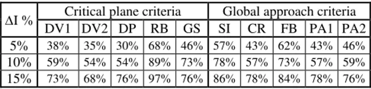
TABLE II
Percentage of fatigue tests data for Test type 1 (37 tests)
I % Critical plane criteria Global approach criteria DV1 DV2 DP RB GS SI CR FB PA1 PA2 5% 38% 35% 30% 68% 46% 57% 43% 62% 43% 46%
10% 59% 54% 54% 89% 73% 78% 57% 73% 57% 59%
15% 73% 68% 76% 97% 76% 86% 78% 84% 78% 76%
TABLE III
Percentage of fatigue tests data for Test type 2 (53 tests)
I % Critical plane criteria Global approach criteria DV1 DV2 DP RB GS SI CR FB PA1 PA2 5 32% 28% 60% 25% 58% 26% 22% 55% 22% 55%
10 57% 47% 81% 47% 92% 51% 40% 85% 40% 83%
15 70% 64% 92% 62% 98% 70% 57% 96% 57% 96%
This table highlights the fact that the RB criterion gives the best prediction when the directions of the principal stresses are invariable with time. Thus the criteria FB, PA1 and GS has to be chosen when the direction of the principal stresses are mobiles.
In test situation where the directions of the principal stresses are invariable with time, a fixed number of critical planes are evident. On the other hand infinite number of critical planes are evident, when the direction of the principal stress changes during a stress cycle [14].
The fact that the critical plane criterion credited to ROBERT-BAHUAUD gives the best results for test type one indicated that a knowledge of the level of crack initiation of the most stressed planes is sufficient to predict the fatigue behaviour of materials. However, when the direction of the principal stresses changes with time, many planes have to be taken into account when describing the fatigue behaviour – such is the case for the FB and PA2 criteria. It must be noted, however, that if the GS criterion were based on the critical plane concept, its model would contain the boundary of the trace of the load that represents fairly well the changes in the direction of the principal stresses.
V. CONCLUSION From this presentation, two conclusions can be drawn:
First of all, many criteria have been developed and their utilisation to fatigue life computation depends on the nature of the stress state as well as the nature of material. The best criterion is the one which has the highest percentage of index validity.
Secondly, criteria based on the critical plane concept find better applicability in situation where the direction of the principal stresses remains invariable with time. However, if the directions of the principal stresses are mobile during a loading cycle as is often the case in practice, the criteria based on the global concepts performs better in predicting fatigue behaviour.
This study also opens up new research opportunities such as the development of a law of crack initiation adapted to random multiaxial loads, cycles counting and the computation and summing crack initiation indicators of micro planes.
REFERENCES
[1] Hohenemser K., Prager W., “The problem of fatigue strength under complex stresses”, Metallwirt-schaft XII, 24, 1933.
[2] Gough H. J., Pollard H. V., “The strength of metals under combined alternating stresses”, Proceeding of the Institution of Mechanical Engineers, vol.131, N0 3,1935.
[3] Dang Van K., Cailleteaud G., Flavenot J.F., LE Douaron, Lieurade H. P., “Critère d’amorçage en fatigue à grands nombres de cycles sous sollicitations axiales”, Institut de Recherches de la Sidérurgie Française (IRSID), Juin 1984, R.E. 1123
[4] Dang Van K., Griveau B., Message O., “On a multiaxial fatigue criterion. Theory and application”, Rapport SKF, R.E. 1123, p. 45 [5] Robert J. L., “Contribution à l’étude de la fatigue sous sollicitations périodiques ou aléatoires”. Thèse de l’institut National des
Sciences Appliquées (INSA) de Lyon, N0 ordre 92 ISAL 0004, Janv. 1992, 229 p.
[6] Galtier A., Seguret J., “Critères multiaxiaux en fatigue exploitation en bureau d’étude. Proposition d’un nouveau critère”, Revue Française de Mécanique, 1990, N04, p. 291-299.
[7] Deperrois A., “Sur le calcul des limites d’endurance des aciers”, Thèse de l’Ecoie Polytechnique, 1991.
[8] Sines G., “Failure of materials under combined repeated stresses with superimposed static stress”, National Advisory Committee for Aeronautics (N.A.C.A). Washington. Technical Note 3495, November 1955, 69 p.
[9] Crossland B., “Effect of large hydrostatic pressures on the torsional fatigue strength of an alloy steel”, Proceeding of the International Conference on fatigue of metals. institution of Mechanical Engineers, London, 1956, p. 138-149.
[10] Grubisic V., Simburger A., “Fatigue under combined out-of-phase multiaxial stresses. Proceeding of the International Conference on fatigue testing and design. Society of Environmental Engineers, London, 1976.
[12] Papadopoulos l.V., “Fatigue polycyclique des métaux une nouvelle approche”, Thèse de l’Ecole Nationale des Ponts et haussées, 18 Déc. 1987, 443 p.
[13] Papadopoulos l.V., “Fatigue limit 0fmetals under multiaxial stress conditions. The microscopic approach.”, Technical Note N0 1.93-101, Commission of the European Communites, Joint Research Centre, IESEI/IE 2494/93, 1993.
[14] B. Kenmeugne, “Contribution à la modélisation du comportement en fatigue sous sollicitations multiaxiales d’amplitude variable”. Thèse de l’institut National des Sciences Appliquées (INSA) de Lyon, N0 ordre 96 ISAL 0064, JuiI. 1996, 286 p.
[15] Lemaitre J., Chaboche J.L., “Aspect phénoménologique de la rupture par endommagement”, Journal de Mécanique Appliquée, 1978, vol. 2, N0 3, p. 317-363.
[16] Fogue M., Kenmeugne B., Salle-V1dal E., Robert J.L., Bahuaud J., “Prise en compte de l’effet des contraintes moyennes de compression par un critère de fatigue”, 12è Congrès Français de Mécanique, Strasbourg, Sept. 1995, p. 365-368.
[17] Ngargueudedjim K., “Prise en compte du gradient de contrainte dans les critères de fatigue muitiaxiaux”, Mémoire de DEA de l’INSA de Lyon, 28 Juil. 1997, 96 p.
[18] Simburger A., “Festigkeitsverhalten zaher Werkstoffe bei einer mehrachsiger phasenverschobenen Schwingbeanspruchung mit korperfesten und veranderlichen Hauptspannungsrichtungen”. Laboratorium fùr Betriebsfestigkeit (L.B.F.), Darmstadt, Bericht, Nr-FB-121, 1975, 247 p.
[19] Mielke S., “Festigkeitsverhaiten metallischer Werkstoffe unter zweiachsigschwingender Beanspruchung mitverschiedenen Spannunszeitverlaufen”, Diss. TH Aachen, 1980, 89 p.
[20] Heidenreich R., Richter I., Zenner H., “Schubspannungsintensitatshypotheseweitere experimentelle und theorestiche Untersuchungen, Konstruction, 1984, N0 36 H. 3 - p. 99 - 104.
[21] Froustey C., Lasserre S., “Fatigue des aciers sous sollicitations combinées. Application à l’acier 3ONCD16” Rapport DRET - LAMEF - ENSAM -Bordeaux. 1988.
[22] Y. Nadot, T. Billaudeau, “Multiaxial fatigue limit criterion for defective materials”., Engineering Fracture Mechanics, Nr 73 (2006), pp. 112-133
[23] Yongming Liu, Sankaran Mahadevan, Multiaxial high-cycle fatigue criterion and life prediction for metals, International Journal of Fatigue, Volume 27, Issue 7, July 2005, Pages 790-800, ISSN 0142-1123, DOI: 10.1016/j.ijfatigue.2005.01.003.
[24] A. Berrehili, Y. Nadot, S. Castagnet, J.C. Grandidier, C. Dumas, Multiaxial fatigue criterion for polypropylene - Automotive applications, International Journal of Fatigue, Volume 32, Issue 8, August 2010, Pages 1389-1392, ISSN 0142-1123, DOI: 10.1016/j.ijfatigue.2010.01.008.
[25] Taner Gocmez, Ali Awarke, Stefan Pischinger, A new low cycle fatigue criterion for isothermal and out-of-phase thermomechanical loading, International Journal of Fatigue, Volume 32, Issue 4, April 2010, Pages 769-779, ISSN 0142-1123, DOI: 10.1016/j.ijfatigue.2009.11.003.
[26] Q.H. Vu, D. Halm, Y. Nadot, Multiaxial fatigue criterion for complex loading based on stress invariants, International Journal of Fatigue, Volume 32, Issue 7, July 2010, Pages 1004-1014, ISSN 0142-1123, DOI: 10.1016/j.ijfatigue.2009.11.006.
[27] Ekberg, A. et P.,Sotkovski. (2000). ―Anisotropy and rolling contact fatigue of railway wheels. International Journal of Fatigue , 29-43.
[28] Cano, F., A. Constantinescu et H. Maitournam. (2004). ―Critère de fatigue polyciclique pour des matériaux anisotropes: application aux monocristaux. C. R.Mécanique 332.
[29] Pessard E. Comportement anisotrope en fatigue des composants mécaniques forgés. Thèse de doctorat. Université d’Angers. N° 998. 2009. 214 P.
[30] B. Kenmeugne, B. D. Soh Fotsing, G. F. Anago, M. Fogue, J-L. Robert. Application of Multiaxial Fatigue Criteria to Mechanical Design. Int. Review of Mech. Eng. Vol 5, N°3, 2011.