HU
FI
RO
UGO
ILIPE PIN
ODRIGU
NHEIRO
UES
Co
ar
Bi
co
omporta
rmado
iaxial sei
olumns
mento s
ismic be
ísmico b
ehaviour
biaxial de
of reinfo
e pilares
orced co
de betão
ncrete
o
HU
FI
RO
UGO
ILIPE PIN
ODRIGU
NHEIRO
UES
Co
ar
Dis req rea Va Civ Dia Fa Ap Un bo BDomporta
rmado
ssertação ap quisitos nece alizada sob a arum, Profess vil da Univer as Arêde, Pr aculdade de E poio financeir niversidade d lsa de Douto D/REITORIA/amento s
presentada à essários à ob a orientação sor Associad rsidade de Av rofessor Asso Engenharia d ro da Reitoria de Aveiro atr oramento /4/47/2008sísmico b
à Universidad btenção do g científica do do com Agre veiro e coori ociado do De da Universid a da avés dabiaxial de
de de Aveiro grau de Douto o Doutor Hum gação do De entação do D epartamento ade do Porto Apoio finan âmbito do Q 4.1 - Forma comparticip Europeu e MCTES atr doutoramene pilares
para cumpr tor em Engen mberto Salaz epartamento Doutor Antón o de Engenha o. nceiro da FCT QREN - POP ação Avança pado pelo Fu por fundos n ravés da bols nto SFRH/BDs de betã
imento dos nharia Civil, zar Amorim de Engenha nio José Coe aria Civil da T e do FSE n PH - Tipologi ada, undo Social nacionais do sa de D/63032/200ão
aria elho no a 09HU
FI
RO
UGO
ILIPE PIN
ODRIGU
NHEIRO
UES
Bi
Th the su Ag co the Fin Un graiaxial seis
esis submitt e degree of D pervision of ggregation at -supervision e Faculty of E nancial supp niversity of Av ant BD/REITsmic beh
ted to the Un Doctor of Phi Dr. Humbert t the Civil En of Dr. Antón Engineering ort provided Aveiro through TORIA/4/47/2aviour of
niversity of Av ilosophy in C to Salazar Am gineering De nio José Coe of the Unive by the h the PhD 2008f reinforce
veiro to fulfil Civil Enginee morim Varum epartment of elho Dias Arê rsity of Porto Financial su and FSE in POPH - Typ Training, su Social Fund MCTES thr SFRH/BD/6ed concre
the requirem ring, under t m, Associate f the Univers êde, Associa o. upport provid n the Framew pologies 4.1 upported by d and Nation rough the Ph 63032/2009ete colum
ments to obta he scientific Professor w ity of Aveiro te Professor ded by the F work of QREN - Advanced the Europea nal funds of t hD grantmns
ain with and r at CT N - an he“...
O Mundo não se fez para pensarmos nele (Pensar é estar doente dos olhos) Mas para olharmos para ele e estarmos de acordo... Eu não tenho filosofia: tenho sentidos... Se falo na Natureza não é porque saiba o que ela é, Mas porque a amo, e amo-a por isso, Porque quem ama nunca sabe o que ama Nem sabe por que ama, nem o que é amar ... Amar é a eterna inocência, E a única inocência não pensar... “ In O Guardador de Rebanho Alberto Caeiro
o júri
presidente Prof. Doutor João de Lemos Pinto
Professor catedrático da Universidade de Aveiro´
vogais Prof. Doutor José Manuel Jara Guerrero
Professor Titular da Universidad Michoacana San Nicolás de Hidalgo, Morelia, México
Prof. Doutor Aníbal Guimarães da Costa
Professor Catedrático da Universidade de Aveiro
Prof. Doutor Humberto Salazar Amorim Varum
Professor Associado com Agregação da Universidade de Aveiro
Prof. Doutor António José Dias Arêde
Professor Associado da Faculdade Engenharia da Universidade do Porto
Prof. Doutor Alfredo Peres de Noronha Campos Costa
Investigador Principal do Laboratório Nacional de Engenharia Civil
Prof. Doutor Rui Jorge Silva Moura Pinho
Professor Auxiliar da Università degli Studi di Pavia, Itália
Prof. Doutor Nelson Saraiva Vila Pouca
Professor Auxiliar da Faculdade de Engenharia da Universidade do Porto
Prof. Doutor Patrício António Almeida Rocha
Professor Adjunto da Escola Superior de Tecnologia e Gestão do Instituto Politécnico de Viana do Castelo
acknowledgements The present work has been developed at the Civil Engineering Department of Aveiro University and at the LESE, Laboratory of Earthquake and Structural Engineering laboratory of the Faculty of Engineering of the University of Porto. I wish to express my sincere gratitude to the following persons, which have contributed to make this work possible and helped me growing.
I would like to express my gratitude to my advisor, Professor Humberto Varum, for his support and guidance throughout the research. Along these years he stimulated not to be only a PhD student but to go further, giving me the opportunity to take part in many other activities.
To Professor António Arêde, my co-supervisor I would like to express my appreciation for his precious advices, trust and tremendous support in the development of the experimental campaign.
To Professor Aníbal Costa for his support and contributions along the development of this work. Since the beginning he was enthusiastic with this project in particular inciting me for the improvement of the simplified model. I would like to thank to Xavier Romão for the interesting discussions, support and information supplied, to Pedro Delgado and Patrício Rocha, for the knowledge and information given from previous experiments, and to Romeu Vicente for the long talks and continuous encouragement.
To Professor António Gil Andrade Campos I would like to express my sincere gratitude for all the support and assistance in the application of the optimization methodologies.
I should emphasize that the experimental work described in this thesis would not have been possible without the assistance of LESE laboratory personnel, in particularly Valdemar Luís, André Martins and Luís Noites. Without them, these experiments would not be pleasant.
To all my colleagues from the PhD room in University of Aveiro, in particular to Helena Paiva, Catarina Fernandes and Carlos Couto, I would like to thank for their patience supporting my moods and my loud music over this years. I am also grateful to my friends, for their support, patience and for continuing being my friends despite frequently missing my company. I would also like express my thanks to my grandparents, parents and brother for all their love and support throughout my life.
Finally, I would like to dedicate this thesis to Marisa and Maria Carolina, for their support, love and for always being my core.
palavras-chave Pilares de betão armado, comportamento cíclico, ensaios experimentais biaxiais, modelos não-lineares refinados, modelos não-lineares simplificados
resumo A análise dos efeitos dos sismos mostra que a investigação em engenharia
sísmica deve dar especial atenção à avaliação da vulnerabilidade das
construções existentes, frequentemente desprovidas de adequada resistência sísmica tal como acontece em edifícios de betão armado (BA) de muitas cidades em países do sul da Europa, entre os quais Portugal. Sendo os pilares elementos estruturais fundamentais na resistência sísmica dos edifícios, deve ser dada especial atenção à sua resposta sob ações cíclicas. Acresce que o sismo é um tipo de ação cujos efeitos nos edifícios exige a consideração de duas componentes horizontais, o que tem exigências mais severas nos pilares comparativamente à ação unidirecional.
Assim, esta tese centra-se na avaliação da resposta estrutural de pilares de betão armado sujeitos a ações cíclicas horizontais biaxiais, em três linhas principais.
Em primeiro lugar desenvolveu-se uma campanha de ensaios para o estudo do comportamento cíclico uniaxial e biaxial de pilares de betão armado com esforço axial constante. Para tal foram construídas quatro séries de pilares retangulares de betão armado (24 no total) com diferentes características geométricas e quantidades de armadura longitudinal, tendo os pilares sido ensaiados para diferentes histórias de carga. Os resultados experimentais obtidos são analisados e discutidos dando particular atenção à evolução do dano, à degradação de rigidez e resistência com o aumento das exigências de deformação, à energia dissipada, ao amortecimento viscoso equivalente; por fim é proposto um índice de dano para pilares solicitados biaxialmente. De seguida foram aplicadas diferentes estratégias de modelação não-linear para a representação do comportamento biaxial dos pilares ensaiados, considerando não-linearidade distribuída ao longo dos elementos ou concentrada nas extremidades dos mesmos. Os resultados obtidos com as várias estratégias de modelação demonstraram representar adequadamente a resposta em termos das curvas envolventes força-deslocamento, mas foram encontradas algumas dificuldades na representação da degradação de resistência e na evolução da energia dissipada.
Por fim, é proposto um modelo global para a representação do comportamento não-linear em flexão de elementos de betão armado sujeitos a ações biaxiais cíclicas. Este modelo tem por base um modelo uniaxial conhecido, combinado com uma função de interação desenvolvida com base no modelo de Bouc-Wen. Esta função de interação foi calibrada com recurso a técnicas de otimização e usando resultados de uma série de análises numéricas com um modelo refinado. É ainda demonstrada a capacidade do modelo simplificado em reproduzir os resultados experimentais de ensaios biaxiais de pilares.
keywords RC columns, cyclic behaviour, biaxial experimental testing, refined non-linear modelling, simplified non-linear modelling
abstract Recent earthquakes around the world have shown that earthquake engineering
research should focus on the vulnerability assessment of existing
constructions. Quite often these constructions are lacking adequate seismic resistance as in the case of several reinforced concrete buildings.
Since the columns are key structural elements for the adequate seismic performance of buildings, special attention should be given to their structural response under load reversals. Moreover, earthquake effects generally require the inclusion of two horizontal component loads that are recognized to be more damaging than one-direction actions.
The present thesis focuses on the assessment of the structural response of RC columns under bidirectional horizontal loads in three main streamlines.
First, an experimental testing campaign was performed on 24 rectangular building columns, for different types of loading. Two specimens of each column cross-section type were uniaxially tested, one in each direction (strong and weak). All the other specimens were tested under bidirectional loading conditions for different paths. All columns were tested under constant axial loading conditions. The experimental results are presented and the global behaviour of the tested columns is discussed, particularly focusing on the damage evolution, stiffness and strength degradation associated to the increasing demands, energy dissipation and equivalent viscous damping. In this framework, one proposal is introduced for a biaxial damage index and validated against the experimental results.
Subsequently, the tested columns were simulated with different non-linear modelling strategies. The studied models are classified into two categories, according to the non-linearity distribution assumed in the elements: lumped-plasticity and distributed inelasticity. The analyses show that the global envelope response is satisfactorily represented with different modelling strategies, but significant differences were found in terms of strength degradation for higher drift demands and of energy dissipation.
Finally, a simplified hysteretic model is proposed for the representation of the non-linear response of reinforced concrete members subjected to biaxial bending combined with constant axial load. The proposed model corresponds to an upgrade of an existing uniaxial hysteretic model, with piecewise linear behaviour, and adopts an interaction function based on the formulation of Bouc-Wen smooth hysteretic model. The proposed biaxial model requires the same type of information as for the corresponding uniaxial one, along with a correcting term given by an interaction function which modifies the response in each uniaxial direction in order to couple the two directions’ responses. For the calibration of the proposed interaction function, optimization techniques were used in order to adjust the required parameters. The validity of the simplified model is demonstrated through the simulation of the response of reinforced concrete columns tested under biaxial loading.
Table of Contents
TABLE OF CONTENTS ... I LIST OF FIGURES ... V LIST OF TABLES ... XIII
CHAPTER 1 - INTRODUCTION ... 1
1.1 GENERAL ... 1
1.2 RESEARCH PROGRAMME OBJECTIVES ... 4
1.3 THESIS SCOPE AND ORGANIZATION ... 4
CHAPTER 2 - REVIOUS RESEARCH AND BACKGROUND ... 7
2.1 INTRODUCTION ... 7
2.1.1 Typical causes and consequences of column failure during earthquakes ... 8
2.1.2 Hysteretic behaviour of RC columns ... 12
2.2 EXPERIMENTAL STUDIES ON THE SEISMIC BEHAVIOUR OF RC COLUMNS ... 15
2.2.1 Introduction ... 15
2.2.2 Specimen geometries ... 18
2.2.3 Displacement patterns ... 19
2.2.4 Behaviour of RC columns under biaxial bending with constant axial load ... 21
2.2.5 Behaviour of RC columns under biaxial bending with varying axial load ... 25
2.2.6 Biaxial tests on global bare frame structures ... 26
2.3 NUMERICAL MODELLING OF BIAXIAL BENDING OF RC COLUMNS ... 29
2.3.1 Introduction ... 29
2.3.2 Numerical modelling strategies at the element level ... 30
2.3.3 Modelling biaxial flexure with axial force ... 31
2.4 FINAL REMARKS ... 34
CHAPTER 3 - TEST PROGRAM ... 37
3.2 SPECIMENS AND CONSTRUCTION ... 38
3.2.1 Introduction ... 38
3.2.2 Prototype columns: geometry and section detailing ... 39
3.2.3 Construction ... 40
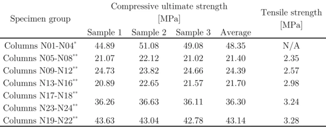
3.3 MATERIAL PROPERTIES ... 41
3.3.1 Concrete... 42
3.3.2 Reinforcement steel ... 43
3.4 AXIAL LOAD ... 44
3.5 HORIZONTAL DISPLACEMENT PATHS ... 45
3.6 TEST SET-UP AND INSTRUMENTATIONS ... 47
3.6.1 Test set-up ... 47
3.6.2 Instrumentation ... 49
CHAPTER 4 - ANALYSIS OF EXPERIMENTAL TEST RESULTS ... 53
4.1 GENERAL OVERVIEW ... 53
4.2 DAMAGE EVOLUTION IN THE TESTED COLUMNS ... 54
4.2.1 Observed damage ... 54
4.2.2 Damage distribution ... 57
4.2.3 Damage versus drift demand ... 59
4.2.4 Performance objective ... 62
4.3 FORCE-DISPLACEMENT HYSTERETIC BEHAVIOUR ... 64
4.3.1 Global analysis ... 64
4.3.2 Evaluation of the yielding displacement ... 72
4.3.3 Influence of the biaxial loading path on the columns’ ultimate ductility ... 74
4.3.4 Coupling effect in the columns’ biaxial response ... 75
4.3.5 Correlation between maximum strength and yield strength ... 77
4.4 STRENGTH DEGRADATION ... 77
4.5 STIFFNESS DEGRADATION ... 80
4.6 DISSIPATED ENERGY ... 83
4.6.1 Cumulative dissipated energy ... 83
4.6.2 Individual cycle energy ... 85
4.6.3 Total dissipated energy until conventional collapse ... 87
4.6.4 Normalized dissipated energy vs displacement ductility ... 89
4.7 EQUIVALENT VISCOUS DAMPING RATIO ... 91
4.7.1 Evaluation of equivalent damping from experimental results ... 91
4.7.2 Empirical proposals for equivalent damping in RC elements under uniaxial loadings ... 97
4.7.3 Equivalent biaxial damping ... 99
4.8 ULTIMATE DISPLACEMENT CAPACITY ... 101
4.9 DAMAGE QUANTIFICATION ... 105
iii
4.9.2 Application of Park and Ang damage index to the uniaxial tests ... 107
4.9.3 Proposals of damage index for RC columns under biaxial loading conditions 109 4.9.4 Results ... 110
4.10 FINAL REMARKS ... 113
CHAPTER 5 - NON-LINEAR ANALYSIS OF RC COLUMNS SUBJECTED TO BIAXIAL LOADS ... 117
5.1 INTRODUCTION AND OBJECTIVES ... 117
5.2 NUMERICAL TOOL AND MODELLING STRATEGIES ... 118
5.3 ELEMENT MODELLING STRATEGIES ... 118
5.4 MATERIALS PROPERTIES ... 120
5.4.1 Concrete ... 120
5.4.2 Reinforcement steel ... 120
5.5 COMPARISON BETWEEN MODELLING STRATEGIES ... 121
5.5.1 Shear drift envelopes ... 121
5.5.2 Cyclic response ... 127
5.6 FINAL REMARKS ... 133
CHAPTER 6 - SIMPLIFIED MODEL FOR THE NON-LINEAR BEHAVIOUR OF RC COLUMNS UNDER BIAXIAL BENDING ... 135
6.1 INTRODUCTION ... 135
6.2 UNIAXIAL HYSTERETIC MODEL ... 136
6.3 BIAXIAL BOUC-WEN MODEL ... 138
6.3.1 Background ... 138
6.3.2 Framework of the proposed biaxial model ... 141
6.4 PARAMETER IDENTIFICATION FOR THE SCALING INTERACTION FACTOR ... 142
6.4.1 Optimization method ... 142
6.4.2 Optimization of the interaction function ... 144
6.5 VALIDATION OF THE MODEL WITH RESULTS FROM CYCLIC TESTS ... 149
6.5.1 Introduction ... 149
6.5.2 Analysis of the results ... 149
6.6 FINAL COMMENTS ... 154
CHAPTER 7 - CONCLUSIONS AND FUTURE RESEARCH ... 157
7.1 SUMMARY OF CONCLUSIONS ... 158
7.2 FUTURE DEVELOPMENTS... 160
APPENDIX A – EXPERIMENTAL RESULTS ... A.1 APPENDIX B – NUMERICAL SIMULATIONS ... B.1 APPENDIX C - PUBLICATIONS ... C.1
List of Figures
Figure 1 - Flexural deficient behaviour in RC columns: a) in the San Salvatore hospital, in the 2009 L’Aquila Earthquake; b) rectangular column in residential building in the 2011 earthquake in Lorca, Spain ... 8 Figure 2 - Shear deficient behaviour in RC columns in residential buildings in the 2009
L’Aquila Earthquake: a) square column [26]; b) circular column [27]; failure is related to the transversal reinforcing steel; c) deficient flexural/shear behaviour in a corner column in a residential building in the 2011 earthquake in Lorca, Spain ... 10 Figure 3 - Inadequate joint behaviour in residential buildings: a) inappropriate anchorage of
beam longitudinal reinforcement b) deficient detailing of a beam-column joint in a residential building (2009 earthquake in L’Aquila, Italy); c) RC building collapse in the 2011 earthquake in Lorca, Spain ... 11 Figure 4 - Column failure due the presence of non-structural elements. Short column effect
caused by window openings in residential building: a) 2009 earthquake in L’Aquila, Italy; and b) 2011 earthquake in Lorca, Spain ... 12 Figure 5 - Example of a lateral force-displacement cyclic behaviour of a RC Column [37] .. 13 Figure 6 - Interaction surface for biaxial load column ... 14 Figure 7 - Experimental tests on RC rectangular columns according to function of the
loading conditions: uniaxial or biaxial; and constant (CAL) or variable axial load (VAL). Statistics based on a review of the literature and test databases ... 17 Figure 8 - Column test configurations ... 18 Figure 9 – Load paths used by different authors ... 20
Figure 10 – Otani et al. Test SP7 [32, 39]: Measured displacements force paths and hysteresis loops ... 22 Figure 11 – Bousias Test S9 [43]: (a) measured displacement and force path; (b) Hysteresis loops; and (c) phase lag between measured force and imposed displacement ... 23 Figure 12 – Kawashima et al. [44]: Lateral force vs. lateral displacement hysteresis under
cyclic loadings ... 24 Figure 13 – Oliva and Clough [70]: Test frame and column section dimension ... 27 Figure 14 – Oliva and Clough [70]: Moment vs base rotation results from a rectangular
column ... 28 Figure 15 – Element model approaches for non-linear numerical modelling of RC
beam\column ... 30 Figure 16 – Fibre element: distribution of control sections and section subdivision into
fibres (adapted from [104]) ... 32 Figure 17 – Triaxial spring model [18] ... 33 Figure 18 - General scheme of the column specimens and testing directions ... 38 Figure 19 - RC column specimens’ dimensions and reinforcement detailing: a) cross-sections
details; b) specimen dimensions and general scheme of the reinforcement layout ... 40 Figure 20 – Construction of the columns: a) formwork and column footing; b) column
connection; c) stirrups in place; d) column casting; e) concrete vibration with a vibrating needle; f) specimens after removing the framework ... 41 Figure 21 – Steel stress-strain curves: a) columns N01-N04; b) columns N05-N16 c) columns
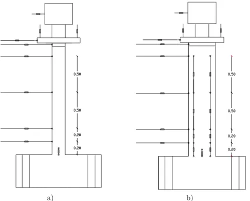
N17-N24 ... 44 Figure 22 – Type displacement paths ... 46 Figure 23 - Testing setup at LESE laboratory: schematic layout ... 47 Figure 24 –Testing setup at LESE laboratory: general view ... 47 Figure 25 – Axial load actuator and sliding steel plates at the top column ... 48 Figure 26 – PXI controller and data acquisition systems ... 49 Figure 27 - Displacement instrumentation scheme adopted: a) lateral displacement
transducers for the East-West direction; b) lateral displacement transducers for the North-South direction lateral displacement and relative displacement transducers along the East and West face ... 50
vii
Figure 28 – External steel frame to support the LVDT’s to measure the horizontal
displacements in the two orthogonal directions ... 51 Figure 29 – Inverted rollers to support vertical transducers in the West face of the column
to measure the relative displacements along the column height in biaxial tests: a) Generic view; b) detail view ... 51 Figure 30 –Example of the crack in the base of the column (specimen PB01-N09) ... 55 Figure 31 – Crack evolution in the East face of column PB01-N09 ... 55 Figure 32 – Damage states: a) cracking; b) spalling at the column corner; c) spalling at the
overall column section width and longitudinal reinforcement buckling; d) corner bars rupture ... 56 Figure 33 – Stirrup failure in column PB12-N11 due to hoop rupture ... 56 Figure 34 – Damage evolution in the columns N15 and N24, subjected to different axial
load ratios but to the same horizontal loading path ... 57 Figure 35 – Plastic hinge length (adapted from [36]) ... 58 Figure 36 – Examples of damage distribution in a 30 x 50cm RC column subjected to
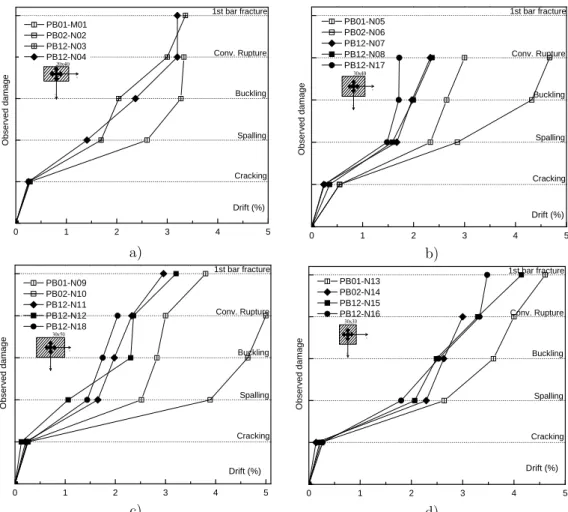
different uniaxial and biaxial loading paths ... 58 Figure 37 – Drift associated with each damage state for different load paths (uniaxial and
biaxial) ... 61 Figure 38 – Correlation between the ratios (biaxial/uniaxial) of drift demand corresponding to concrete spalling and bar buckling ... 61 Figure 39 – Influence of the axial load on the drift associated with each damage state for
biaxially loaded columns ... 62 Figure 40 – Influence of the cycle repetition on the drift associated with each damage state
for biaxially loaded columns ... 62 Figure 41 – experimental drifts for each damage state and drift limits according to the
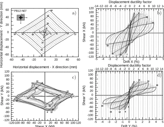
FEMA 356 [90], VISION 2000 [130] ... 64 Figure 42 – Global results of rectangular column PB12-N07 for rhombus load path ... 65 Figure 43 – Global results of rectangular column PB12-N12 for rectangular load path ... 65 Figure 44 – Global results of rectangular column PB18-N12 for circular load path ... 66 Figure 45 – Envelopes for different load paths ... 68 Figure 46 – Envelopes for different levels of axial force ... 69 Figure 47 – Envelopes for same load path with and without cyclic repetition ... 69
Figure 48 – Effect of the biaxial load path in the maximum columns’ strength ... 69 Figure 49 – Proposed method for the definition of yielding displacement ... 74 Figure 50 – Phase lag between measured horizontal forces and imposed horizontal
displacements for circular load paths ... 76 Figure 51 – Correlation between maximum and yielding strength ... 77 Figure 52 – Strength degradation under cyclic loading ... 78
Figure 53 – Normalized strength degradation (2nd and 3rd cycle) for different load paths ... 79
Figure 54 – Normalized strength degradation (2nd and 3rd) cycle for different levels of axial
load ... 80 Figure 55 – Stiffness degradation ... 81 Figure 56 – Stiffness degradation for different load paths ... 82 Figure 57 – Stiffness degradation for different levels of axial load ... 82 Figure 58 – Comparison of cumulative dissipated energy for columns with different load
paths (uniaxial and biaxial loads) ... 85 Figure 59 – Individual cycle energy and cumulative dissipated energy for rectangular
columns (N09 to N12 and N18) ... 86 Figure 60 – Individual cycle energy and cumulative dissipated energy for square columns
(N13 to N16) ... 86 Figure 61 – Evaluation of total energy dissipated of columns tested for uniaxial and biaxial
loads (with different load paths) ... 88 Figure 62 – Evaluation of total energy dissipated for columns with different axial loads .... 89 Figure 63 – Evaluation of total energy dissipated for columns with and without cycle
repetition... 89 Figure 64 – Normalised dissipated energy vs displacement ductility ... 90 Figure 65 – Damping for a hysteretic half-cycle ... 92 Figure 66 – Equivalent damping vs. maximum ductility demand and best-fit logarithmic
curves from column N13 ... 92 Figure 67 – Best-fit equivalent damping vs. maximum ductility demand for different load
paths ... 94 Figure 68 – Best-fit equivalent damping vs. maximum ductility demand for different levels
ix
Figure 69 – Best-fit equivalent damping vs. maximum ductility demand for the same load path with and without cyclic repetition ... 95
Figure 70 – R2 results for the equation proposals for equivalent damping and each uniaxial
test result ... 98
Figure 71 – R2 results for the equation proposals for equivalent damping and all uniaxial
test result ... 99 Figure 72 – Equivalent damping estimated with empirical expressions and results for all
uniaxial tests ... 99 Figure 73 – Equivalent damping for biaxial tests ... 101 Figure 74 – Best fitted proposals for biaxial equivalent damping ... 101 Figure 75 – Ultimate drift capacity: Experimental vs Analytical (EC8-3 expressions) ... 104 Figure 76 – Damage index evolution for the uniaxial tests ... 108 Figure 77 – Contribution of the maximum deformation component to the DI... 108 Figure 78 – Curves for evaluation of resultant displacement ... 110 Figure 79 – Damage index evolution calculated for each biaxial test with Equation (27) . 113 Figure 80 – Damage index evolution for the biaxial tests according with Equation (33) ... 113 Figure 81 – Fibre based modelling (adapted from [174]) ... 118 Figure 82 – Modelling strategies with corresponding control section: a) lumped-plasticity
element; b) distributed inelasticity element with force-based formulation; c)
distributed inelasticity element with displacement-based formulation ... 119
Figure 83 – Shear-drift envelopes for 30x50cm2 columns (measured and calculated) ... 122
Figure 84 – Correlation coefficients (R2) for the shear-drift envelopes between experimental
and numerical results: a) uniaxial texts; b) biaxial tests – strong direction (X); c) biaxial tests – weak direction (Y) ... 123 Figure 85 – Initial stiffness ratio between experimental and numerical results: a) uniaxial
texts; b) biaxial tests – strong direction (X); c) biaxial tests – weak direction (Y) ... 124 Figure 86 – Secant stiffness evolution for columns PB01-N1, PB02-N6, N7 and
PB12-N12: experimental and numerical results ... 125 Figure 87 – Tangent stiffness evolution for columns PB01-N1, PB02-N6, PB12-N7 and
PB12-N12: experimental and numerical results ... 126 Figure 88 – Shear-drift response for columns PB01-N1, PB02-N6, PB12-N7 and PB12-N12:
Figure 89 – FDE index obtained from the comparison of numerical and experimental shear force evolutions: a) uniaxial tests; b) biaxial tests – strong direction (X); c) biaxial tests – weak direction (Y) ... 130 Figure 90 – Evolution of the cumulative dissipated energy for columns PB01-N1, PB02-N6, PB12-N7 and PB12-N12: Experimental and numerical results ... 131 Figure 91 – Ratio between the total dissipated energy obtained with the numerical models
and with the experimental value: a) uniaxial tests; b) biaxial tests – total (X + Y); c) biaxial tests – strong direction (X); d) biaxial tests – weak direction (Y) ... 133 Figure 92 – Pinching effect in the Costa-Costa [179] model ... 137 Figure 93 – Unloading stiffness in the Costa-Costa [179] model ... 137 Figure 94 – Strength degradation in the Costa-Costa [179] model ... 138 Figure 95 – Inverse problem scheme ... 143 Figure 96 – Column cross-section and definition of the lateral loading direction ... 144 Figure 97 – Convergence evolution of the cascade optimization strategies in the parameter
identification ... 147 Figure 98 –Relative Global Error of the simplified model results, with (filled marks) and
without (unfilled marks) interaction function, compared with the refined numerical results... 147 Figure 99 –Examples of pushover curves for different columns and different pushover
loading angles for the refined numerical model, the simplified model without the biaxial bending interaction function and the simplified model with the interaction function ... 148 Figure 100 – Base-shear versus drift of columns N05 and N06 – Uniaxial tests ... 150 Figure 101 – Base-shear versus drift of column N07 – Biaxial test, rhombus displacement
pattern ... 151 Figure 102 – Base-shear versus drift of column N04 - Biaxial test, rhombus displacement
pattern ... 151 Figure 103 – Base-shear versus drift of columns N09 and N10 – Uniaxial tests ... 152 Figure 104 – Base-shear versus drift of column N11 – Biaxial test, rhombus displacement
pattern ... 152 Figure 105 – Base-shear versus drift of column N12 – Biaxial test, quadrangular
xi
Figure 106 – Base-shear versus drift of column N13 – Uniaxial test ... 153 Figure 107 – Base-shear versus drift of column N14 – Biaxial test, rhombus displacement
pattern ... 153 Figure 108 – Base-shear versus drift of column N15 – Biaxial test, quadrangular
displacement pattern ... 154 Figure 109 – Base-shear versus drift of column N16 – Biaxial test, circular displacement
List of Tables
Table 1 – Geometric characteristics of rectangular RC columns tested under biaxial loading (adapted and updated from CEB 220 [32]) ... 19 Table 2 – Nominal values to the concrete considered in the design... 42 Table 3 – Results from compression tests on concrete specimens ... 42 Table 4 – Nominal mechanical properties of steel S400 [121] ... 43 Table 5 – Results from the tensile tests on steel samples ... 44 Table 6 – Test series identification, specimens’ main data and displacement paths ... 46 Table 7 – Length of the damage zone ... 59 Table 8 – Structural Performance Levels and Damage for RC columns adapted from FEMA
356 [90] ... 63 Table 9 – Drift limits according to the (a) FEMA 356 [90], (b) VISION 2000 [130] ... 63 Table 10 – Drift range obtained from experimental tests ... 64 Table 11 – Summary of test results for columns N01 to N04 ... 70 Table 12 – Summary of test results for columns N05 to N08 and N17 ... 70 Table 13 – Summary of test results for columns N09 to N12 and N18 ... 71 Table 14 – Summary of test results for columns N13 to N16 ... 71 Table 15 – Summary of test results for columns N19 to N24 ... 72 Table 16 – Best fit logarithmic curve for global damping for tested each column ... 96 Table 17 – Ultimate drift ratios (experimental/analytical values according to EC8-3) ... 104 Table 18 – Calculated damage index vs. observed damage ... 107 Table 19 – Estimated parameters for RC column damage index calculations ... 107 Table 20 – Damage index ranges for each damage state adopted in the scoring procedure111
Table 21 – Estimated parameters for RC column damage index calculations ... 111 Table 22 – Scores obtained for each column with the different biaxial DI equations ... 112 Table 23 – Concrete mechanical parameters for the numerical model ... 120 Table 24 – Steel mechanical parameters for the numerical model ... 121 Table 25 – Cross-section properties ... 145 Table 26 – Parameters achieved by the cascade optimization strategy ... 146
Chapter 1
Introduction
1.1 General
Looking back over the last decades, it is clear that natural disasters are mostly associated with earthquakes, volcanic eruptions, floods, tsunamis and cyclonic storms and that, most of the time, one natural disaster can induce another, for example tsunamis and earthquakes, or cyclonic storms and floods. These disasters affect many human lives, and cause high financial loss.
In the particular case of earthquakes, in the last year several examples have supported the need for investigation to improve the safety of existing constructions, and have become an important source of information that can help on improving new design methodologies in the evolution of codes and guidelines. For this reason, engineers, architects, planners, builders, contractors and authorities all have an interest in learning from the past. The interest of the scientific community is revealed in the number of papers concerning lessons learned from the study of earthquakes published in International Conferences and journals. These include, for
example, the 14th World Conference on Earthquake Engineering which included a
topic about Lessons Learned from Recent Earthquakes, and at which 73 papers were presented, including 41 at the Special Session about the Wenchuan Earthquake.
Based on observations of building behaviour during earthquakes, Patel [1] points out twelve lessons for structural engineers: i) codes of practice and ethics must be strictly followed, and three-dimensional analysis should be used in a way which considers all types of loads and their worst-case combinations; ii) ductile detailing must be considered; iii) interaction with architects during the early stages of
planning is essential for proper management of structural elements; iv) structural stability and performance should not be compromised by economy and aesthetics;
v) interaction with professional and academic institutes should be maintained for
recent developments; vi) full documentation, including calculations, drawings, etc., must be maintained; vii) fully and detailed drawings should be prepared; viii) there must be insistence on soil investigation, frequent testing of cement, concrete, steel reinforcement; ix) reinforcements must be checked against detailed drawings prior to concreting; x) quality control and site supervision by experienced technical personnel is very important; xi) there should be an emphasis on weigh batching and controlled machine mixing of concrete; xii) vibrators should be used at least to test the foundation, columns and beams.
Bertero [2] performs an identification and analysis of the problems in the USA, based on the lessons learned from the earthquakes in Chile and Mexico in 1985. Recognizing that, after the analysis of the US regulations, the performance of buildings cannot only be enhanced by increasing the seismic loads, the design should take into account the three-dimensional capacity of the soil-foundation-building system and not simply the bare superstructure. Even with improvements in the design procedures, the greatest need is in the improvement of construction and maintenance procedures. In fact, many authors point out the need of improving the quality of construction, in particular the quality of both materials and workmanship [3-9].
The earthquake events and the observed damage has resulted in an evolution in the codes and guidelines; for example, after the Loma Prieta earthquake in 1989, structurally inadequate behaviour has led the US authorities to revise and propose new codes for the seismic safety of buildings and bridges [10]. After the Kobe earthquake in 1995, a study developed by Ohbayashi Corporation [11] has showed an influence of the seismic codes: in Japan, the first seismic codes date back from the 1920s and have undergone important revisions in 1971 and recently in 1981. The study verifies that 6% of the construction after 1981 suffered severe damage, and 36% of construction prior to 1971 suffered similar damage. For the buildings with moderate damages, this effect was not so evident: the moderate damage was identified in 22% of the buildings prior to 1971, and in 11% of the buildings constructed after 1981.
In contrast, Spence [12] observed that, despite the several earthquakes that have occurred over many years in Iran and the evolution of the National Seismic Codes, the country appears powerless in considering earthquake risk, and it would appear that seismic damage has increased rather than decreased in recent decades.
In Portugal, after the Lisbon earthquake of 1755, and later after the Benavente earthquake in 1969 [13], seismic safety was taken into account in construction. However, it was only in 1958 that the first design code concerning the seismic
Introduction 3
safety of buildings [14] was published. This document was used until 1961, with the introduction of the RSEP [15], and later (1983) replaced by the RSA [16], which has been used during these years for the structural design. Recently was introduced the European seismic standard for the Design of Structures for Earthquake Resistance (Eurocode 8) [17].
The actual seismic design codes highlight linear elastic analysis as a reference for the design of new structures; however it is essential to determine structural properties such as initial stiffness, ultimate capacity and different global and local ductility demands, for evaluating accurately the seismic response [18] which requires non-linear dynamic analyses. In order to perform non-linear dynamic analysis, researchers have developed various modelling strategies, with different levels of refinement and complexity. The option for each category depends on the user objective, and the reliability needed in the representation of the structural behaviour.
Even with the evolution of these modelling strategies, open problems and questions regarding the tridimensional non-linear seismic response and performance of reinforced concrete (RC) structures still exist [19]. Buildings are tridimensional structures and the simplification of the tridimensional into bidimensional models without much loss of accuracy is rather difficult or even impossible. In many situations, biaxial structural interaction and torsional oscillation may arise as a result of structural irregularity, thus affecting the structural response [20].
Structural response during recent earthquakes has indicated that the majority of column failures were caused by high shear stresses, lack of concrete confinement and bidirectional load effects [21]. It is clear that the earthquake-related damage to reinforced concrete elements, due to multiaxial excitation, is much more serious when compared to uniaxial excitation. The damage caused in one direction affects the structural seismic performance in the other direction. In fact, even when the earthquake action is assumed in a single direction, the existent structural irregularities in many buildings induce a biaxial behaviour.
Therefore is very important to study the three-dimensional behaviour of buildings, and the recent seismic codes and guidelines point the three-dimensional dynamic analysis as the most accurate, that should drive the future of structural engineering. Nevertheless, many difficulties are still identified in the numerical representation of the tridimensional response of buildings, motivating further research. In fact, no efficient simplified hysteretic models are available for the biaxial representation of the columns' response, and only sophisticated models can achieve an acceptable representation of columns behaviour [22].
1.2 Research programme objectives
Given the importance of the three-dimensional behaviour of reinforced concrete (RC) structures, in particular the biaxial bending behaviour of reinforced concrete slender columns, the main objective of the present study was the development of experimental assessment of RC columns subject to uniaxial and biaxial horizontal loading, the evaluation of existing models for the simulation of the experimental tests and the improvement of a simplified hysteretic model to predict the cyclic behaviour of columns under biaxial cyclic loads.
The experimental programme was designed to study RC columns under flexural behaviour focusing on the effect of three-dimensional loading histories, for different column geometries. The results of the experimental tests were a major improvement in the available data concerning the biaxial bending behaviour of RC elements, and provided valuable information for the development and validation of the proposed simplified models.
Typical numerical strategies were applied for modelling the experimental tests in order to verify the models ability to represent accurately the response of columns to biaxial demands.
Finally, the improvement of simplified global models for the consideration of the cyclic biaxial bending of RC columns, combined with axial load, is intended to provide one more step towards the definition of a reliable simplified model to be used in non-linear.
1.3 Thesis scope and organization
This thesis is structured into seven chapters. A review of previous research related to experimental and numerical behaviour of RC columns is provided in Chapter 2. Chapters 3 and 4 are devoted to the experimental programme performed in the scope of this Thesis. Chapter 5 deals with the numerical analyses performed with existent approaches. Chapter 6 describes the development and calibration of the simplified model to represent the non-linear biaxial behaviour of RC columns. Finally, Chapter 7 summarizes the main conclusions of the research work, and identifies possible future research directions. The Appendixes include further details on specific topics which are deemed unnecessary to include in the main text for an adequate understanding of the performed work.
Chapter 2 presents an overview of the most common causes of seismic damage and failure modes associated with RC columns in recent earthquakes, and reviews the current state of experimental knowledge of concerning the biaxial behaviour of RC columns. The available numerical strategies for non-linear modelling of reinforced
Introduction 5
concrete elements under biaxial bending are briefly reviewed and special attention is given to member models.
Chapter 3 describes all aspects relating to the test programme of 24 cantilever columns tested under constant axial load and horizontal biaxial cyclic loading, including the test specimen details, material properties, test specimen construction, test set-up, loading procedure and instrumentation scheme.
Chapter 4 provides the analysis of experimental results obtained through the tests, described in Chapter 3, comparing the uniaxial with biaxial response and assessing the effect of the biaxial load path. The effects of several response parameters on the column flexural response are evaluated, such as damage evolution, ultimate displacement, energy dissipation, stiffness and strength degradation, and viscous damping.
The evaluation of existent numerical models currently used for predicting the seismic performance of reinforced concrete columns is presented in Chapter 5. To this end, the experimental results obtained in the experimental programme described in Chapters 3 and 4 are compared with the results predicted using three modelling strategies, based on elements with lumped-plasticity, elements with distributed inelasticity and force-based formulation, and elements with distributed inelasticity and displacement-based formulation.
Chapter 6 is devoted to the description of a simplified hysteretic model developed for the force-deformation behaviour of reinforced concrete members under biaxial loading with axial force. It embodies an existing uniaxial hysteretic model with piecewise linear behaviour as the basis for its development, and proceeds from analogy and comparison with the biaxial formulation of the Bouc–Wen smooth hysteretic model. The validity of the model is demonstrated through the analytical simulation of the biaxial tests presented in Chapters 3 and 4.
Finally, the most relevant results and conclusions of this work are summarized in Chapter 7. Possible future research directions are also suggested.
Chapter 2
Previous Research and
Background
2.1 Introduction
Since columns are key structural elements for the seismic performance of buildings, special attention should be given to their structural response under load reversals. Moreover, earthquake effects generally require the inclusion of two horizontal component loads that are recognized to be more damaging than single direction actions. The interest in the inelastic response of axially loaded members under biaxial bending moment histories is relatively recent, and the available experimental results are limited. This is possibly due in part to the uncertainty of combining histories of bending moments in the two orthogonal directions, adding considerable complications to the problem.
The practical result is that our present-day knowledge of the inelastic behaviour of RC columns under biaxial cyclic moments is very much behind to our understanding of their behaviour under uniaxial cyclic bending with axial load. In fact, besides the fibre based models, the existing simplified analytical models are not mature enough to be incorporated into code standards, by contrast with uniaxial simplified global models which are already accepted in international codes.
This work open
2.1.
The obser majo defici const Varu build bond capac joints vertic prope and f Some defici throu Figu the Chapter ai ks in the fiel problems..1 Typica
during
earthquake rvation of p ority of cases iencies of truction def um [24] poin dings: i) d/anchorage city; iv) in s; vi) influe cal and hor erties; viii) finally, x) st e of these c iencies, for ugh the conture 1 - Flexur 2009 L’Aqui ms at provi ld of biaxia
al cause
g earthq
performanc past seismic s, by the fai RC buildi ficiencies as nts out the lack of /lap-splices nadequate fl ence of the rizontal irre higher mod tructural de categories a which the tribution of ral deficient b ila Earthquak iding a brie l behaviours and co
quakes
ce of RC bu events. The ilure of the ings can b well as wit ten most c stirrups/h slipping a lexural cap infill mason egularities, a des’ effects; ficiencies du re in fact r extensive d many of th behaviour in ke; b) rectan earthquake ef review of of RC coluonsequen
uildings has e collapse o vertical mem be associat th deteriora common ca hoops, con and bond acity; v) in nry on the abrupt chan ix) strong-ue to archite related to d damage or hese causes. RC columns ngular column e in Lorca, S a) past experi umns, and tnces of c
s been well of a RC bui mbers [23]. ed with d ation and st auses of fail nfinement splitting; nadequate s seismic beh nge in struc -beam weak ectural requ design, deta collapse of : a) in the Sa n in residenti Spain imental and o identify tolumn fa
documented lding is cau The seismic design, deta tructural mo ure or dam and duc iii) inadequ shear streng haviour of f ctural and/ k-column m uirements. iling and co f structures an Salvatore al building in d numerical the existingfailure
d from the used, in the c behaviour ailing and odification. mage in RC ctility; ii) uate shear gth of the frames; vii) /or element mechanisms; onstruction can occur hospital, in n the 2011 b) b)Previous Research and Background 9
Columns properly designed for earthquake loading are able to prevent brittle failure and to have a ductile behaviour. In fact adequate reinforcement and detailing is very important in providing the ductile behaviour for the RC elements [25]. Moreover, the flexural behaviour is conditioned by the axial force and by the amount of reinforcement in the plastic hinge region. Figure 1 shows examples of RC columns with failures associated with inadequate flexural capacity, although in these examples shear and confinement deficiencies are also evident (transversal reinforcement with large spacing at the columns extremities).
Deficient flexural behaviour can be more evident in exterior corner columns where varying levels of axial force can be expected during earthquakes, leading to high levels of axial force. In some cases it may be difficult to differentiate flexural compression and shear compression failure, as both take place in or near the column ends and involve crushing [23].
The inadequate transversal reinforcement in terms of size, spacing and detailing is the principal cause of the shear failure of RC columns. This problem can be increased in exterior corner columns in buildings with in-plan irregularities [24]. The columns with shear failure commonly exhibit a diagonal fracture in the column mid zone, as illustrated in Figure 2-a) and b). Another typical cause of shear failure is related with insufficient area of transversal reinforcing steel, with wide spacing and deficiently anchored to the concrete core, where ties should have enough length or proper bar bents to promote adequate splice anchorage (see Figure 2c).
Beam-column connections play also an important role in the seismic behaviour of RC buildings; poor behaviour of beam-column joints can lead to the collapse or severe damage of buildings during earthquakes. In some cases, the beam longitudinal reinforcement is not properly anchored in the beam column joint [23] (see Figure 3a) or there is no adequate transverse reinforcement in the joints (see Figure 3b and c).
The not c [28]. often short cause stairc devel can l relate groun c) Figu buildin circular c) defic contribution considered in In the case n observed. T t portion of ed by openi cases. If thi loped with i lead to she ed to the ab nd floor sto ure 2 - Shear ngs in the 20 column [27]; cient flexural/ building n of non-str n the design e of the infil The first is clear colum ngs in the i is effect is n increased st ear failure o bsence of th orey due to a) deficient beh 09 L’Aquila failure is rel /shear behav g in the 2011 ructural elem n of new bui ll masonry associated w mn, creating infill walls, not consider iffness whic of the colum he infill mas o its use fo haviour in RC Earthquake: lated to the t viour in a corn earthquake i ments to th ildings and panels, two with cases w g the so-call for doors or red in the d ch becomes s mn, as illus sonry panel or car park C columns in a) square co transversal re ner column in in Lorca, Spa he structura in the asses o principal m where maso led short co r windows, design, a sh subjected to strated Figu ls in one sto king or com b) c) residential lumn [26]; b) einforcing stee n a residentia ain al response i ssment of ex mechanisms nry infill wa lumn: this s or for landi ort column o shear force ure 4a. The orey, freque mmercial ar ) eel; al is typically xisting ones have been alls leave a situation is ing slabs of is actually e level that e second is ently in the reas, which
Previous Res induces an storey me masonry p fact can in the outer f Figu anch colum search and Ba n abrupt ch echanism [2 panels can d nduce additi frames [31]. ure 3 - Inadeq horage of bea mn joint in a r buildi ckground ange of the 29, 30]. Mo drive torsion ional uncons quate joint be m longitudin residential bu ng collapse in storey stiff oreover the n phenomen sidered force a) ehaviour in r nal reinforcem uilding (2009 n the 2011 ea fness, leadin asymmetri na not predi es, especiall residential bu ment b) defici earthquake arthquake in ng to a pote ic distribut icted in the y in the con uildings: a) in ient detailing in L’Aquila, Lorca, Spain ential global ion of the e design, and ncrete colum c) nappropriate g of a beam-Italy); c) RC n 11 l soft-infill d this mns of b) C
Figu caus
2.1.
The their impo force prope reinfo In fa steel) consi other struc eleme relev varia exter load The decad non-l study failur betw bidir ure 4 - Colum sed by windo.2 Hyste
seismic beh s elements ortant role s due horiz erties, such orcement, a act, these s ), are the m idered as in r factors c ctural eleme ents. The p ant issue ations in th rnal column level. seismic beh des many linear hyste y, such as: re of the c ween concre ectional) [32 mn failure due ow openings i andretic beh
haviour of R and the c because the zontal loads h as dimens re directly i section char most relevan ndividual me an influenc ents (mason position of because du he axial forc ns, and espe haviour of R studies hav eretic behav i) the conf olumns; iii) ete and ste2-36]. e the presence in residential b) 2011 eart
haviour
RC building connections ey support s, like wind sions, amou influenced b racteristics t in the col embers. In t ce its beha ry infill pan the column uring earth ce level of cially corne RC columns ve been pe viour; severa finement of ) the const eel; v) the e of non-stru building: a) thquake in Loof RC c
gs is depend between t the weight d or earthqu unt of longi by the level and the m umn behavi the case of aviour, as nels, stairs) n in the b quakes inte (that can b er ones, may s is controll erformed to al aspects a f the concre tant or vary e direction a) uctural elemen 2009 earthqu orca, Spaincolumns
dent on the hem. The t of the str uakes. In th itudinal rein of axial and material pro iour under h a column i for exampland the con building geo erior colum be considere y be subject ed by many o character are consider ete core; ii) ying axial of the loa nts. Short co uake in L’Aq e behaviour columns pl ructure and he design, t nforcement d shear force operties (con horizontal lo ncluded in le the atta nnections to ometry can mns show o ed constant ted to a va y aspects, a rize the RC red as key ) the effect load; iv) th ad (unidire olumn effect quila, Italy; of each of lay a very d the shear the column and shear es. ncrete and oads, when a building, ached non-o the non-other be also a only small t); however arying axial and in past C columns factors for and shear he slippage ectional or b)
Previous Research and Background 13
The present study is focused on the behaviour of slender RC columns, with the non-linear hysteric behaviour governed by flexure, and so it is important to recall the hysteretic characteristics of these elements. This illustrative analysis is based on a typical force-deformation response of a RC column subjected to unidirectional load and constant axial force, as presented in Figure 5. The following issues can be highlighted: i) the envelope of the force displacement curve can be seen as an approach to the monotonic response of the section, where two particular points can be identified: the concrete cracking point (C) and the yielding point (Y), each of these points correspond to a reduction of the member stiffness; ii) up to yielding the unloading stiffness is approximately constant, but the dashed lines US1, US2, US3 and US4 indicates that, after the yielding point, the unloading stiffness reduces with increase of the inelastic branch; iii) the point P indicated in Figure 5 point to an effect resulting from the closure of the open cracks, slippage and shear effects, with all factors combined contributing for the reduction of the reloading stiffness, classically referred as pinching effect; and iv) in the last cycles after a large incursion on the inelastic behaviour of the RC column, it can be seen that, for repeated cycles with the same displacement, the loading stiffness and the strength degradation at the peak displacement tends to decrease between successive cycles which is normally associated with concrete degradation and buckling of reinforcement steel. The presented case shows the most relevant inelastic hysteretic features of the response of a slender RC column subjected to horizontal uniaxial load.
Figure 5 - Example of a lateral force-displacement cyclic behaviour of a RC Column [37]
-60 -40 -20 0 20 40 60 -80 -60 -40 -20 0 20 40 60 80 P US4 US3 US1 US2 0 500 1000 1500 2000 2500 -60 -40 -20 0 20 40 60 Top D ispl a ce m ent ( m m ) Step T op f o rc e ( k N) Top displacement (mm) C Y 1
It is respo axial Load behav repea while reduc The conte direc recen biaxi proce in th struc integ surfa Gene Figur gener envel comb Mz). reinfo important onse, such a force that c ding history viour of RC ated cycles e internal cy ctions [40]. design anal ext of unia ctions was ntly the des
ial bending edures based he design ctures need gration over ace [42]. erically, the re 6, where ric case 3 is lope surface binations of The surfac orcement st to be aw s the mater can induce p y is anothe C sections [ post-yieldin ycles after la ysis of a rei axial mome often achi sign of reinf has been d on compu [41, 42]. C to be able r the concr e moment-a e the loadin s described f e (for exam f axial force e depends o eel. Figure 6 - are of the ial and sect particular p er very imp 38, 39]. For ng induce a arge inelast inforced con ents, and t ieved throu forced concr the subjec utational me Computer p e to compu rete cross-s axial force ng cases 1 for biaxial l mple, a failu load and m on the sect Interaction s influence tion propert performances portant iss r uniaxial l a decrease o ic may exhi ncrete colum the combin ugh simplif rete column ct of much ethods have programs fo ute the inte section, in interaction and 2 refer loading. The ure surface) moments in ion dimensi
surface for bia
of other fa ies, P-Delta s. sue which loading, as of loading s ibit a lower mn was usua nation of th fied proced n under to a h research recently be or designing ernal forces order to o of a colum r to the un e interaction ) which is the princip ions and am
axial load col
actors on t a effects, or t affects the mentioned stiffness and strength an ally underta he moment ures. Howe axial compr [41]. Some een develope g reinforced through th obtain the mn is summ niaxial load n is represen obtained fo pal direction mount and lumn he column the level of hysteretic before, the d strength, nd stiffness aken in the ts in both ever, more ression and automatic ed to assist d concrete he stresses interaction marized in ding, and a nted by an or different ns (My and location of
Previous Research and Background 15
For the biaxial loading case, the coupling between the two transverse directions is very important for the response and also dependent on the load path as observed in different studies [22, 34, 43-47]. Bousias et al. [48] have reported the biaxial effect in a series of experiments describing the differences between the uniaxial and biaxial behaviour, especially the reduction of the strength and stiffness with biaxial bending, and the increase of hysteretic energy dissipation.
Another important issue is the column shear span ratio, for low values (say below about 2.5 to 4), the column behaviour can be controlled by the inelastic shear effects [38, 49]. This behaviour leads to a reduction of the energy dissipation capacity and to a stiffness and strength decrease in the hysteretic cycles [33, 50].
2.2 Experimental studies on the seismic behaviour
of RC columns
2.2.1 Introduction
The experimental study of RC elements under earthquake loads is very important since it permits the observation and measurement of the particular performance of the element. Regarding the behaviour of RC elements under lateral loads, a large number of various types of studies have been carried out in past years which, apart from the specific subject of each study, have generally covered elements with or without axial loads, as well as uniaxial and biaxial bending. In the case of zero axial force, these studies are typically associated with beams and, therefore, most of them focus only on the uniaxial behaviour of these elements. Columns are studied with non-zero axial force under uniaxial or biaxial bending and also tested with constant or variable axial load. In the case of slender elements, the behaviour is governed by flexure but, depending on the cross-section geometry and the already mentioned shear span ratio, the shear force can also represent an important subject for the study. Studies of RC elements can therefore also be divided into elements where the global behaviour is governed essentially by flexure or by shear, or by both mechanisms.
In the view of the present study, it is important to perform a retrospective review of experimental tests performed on rectangular columns under horizontal loads, especially with biaxial behaviour.
The response of RC members subjected to axial loads together with biaxial bending moment reversals is recognized as a very important research topic for building structures in earthquake-prone regions. On one hand, studies of the response of RC building columns to earthquake actions deal in general with its three-dimensional response, due to the random characteristics of the earthquake direction, and to the
actual building irregularities. On the other hand, the biaxial features of bending moment histories applied to a given RC column section tend to reduce its actual capacity and to accelerate the strength and stiffness deterioration process during successive load reversals. In addition, the 3D response of frame structures to actual earthquake motions generally does not induce the same type of increased deterioration in beams because they behave essentially in only one direction (vertical), i.e. the potential formation plastic hinges in beams are not aggravated by that fact. This means that both the biaxial loading effects in columns and the 3D features of the general structure response both positively contribute to inelasticity and damage concentration in the columns rather than in the beams, which is essentially the opposite of present-day design code requirements created to avoid collapse of RC frame structures under lateral load reversals (plastic hinges in the beams rather than in the columns) [32].
Experimental research work on the inelastic response of RC members under compression axial force and biaxial lateral cyclic bending loading conditions is currently very limited. Uncertainties concerning the relationship and combination of the two orthogonal horizontal loading paths, associated to the complexity of the experimental set-up, certainly justified this lacuna.
As a consequence, current knowledge concerning the inelastic response of RC columns under biaxial cyclic moments is very much less than that of the uniaxial cyclic bending behaviour with compressive axial load [32, 51, 52].
The available test results for biaxial bending under constant axial load are not so extensive when compared to those on uniaxial bending, although they have been delivered over a period of almost 30 years. On the basis of an extensive analysis of international experimental databases and from a literature review of studies covering tests on rectangular RC columns subjected to cyclic loading, a statistical analysis was performed based on the data collected for 453 column tests (see Figure 7). From the data analysis, it was verified that: i) only 27 of these columns (6%) were tested with variable axial load; and ii) only 56 (12%) were tested in biaxial loading conditions. These statistical figures emphasize the insufficient experimental results for the comprehensive characterization of the biaxial cyclic behaviour of RC columns.
Due to testing difficulties and because there are still open questions regarding the cyclic behaviour both in biaxial bending with constant axial force and in uniaxial bending with simultaneously varying axial load, very few experimental studies have, as yet, tackled the more general problem of biaxial bending with varying axial force [32, 33], as can be seen in Figure 7. From the literature review, only the tests performed by Low and Moehle (two columns) [47] and by Chang (two columns) [53] refer to rectangular cross-sections with different dimensions and
Previous Research and Background 17
amount of longitudinal reinforcement in the two principal directions, leading to different characteristics in terms of stiffness and strength.
In recent years, a very small number of tests have also been performed in beam-columns sub-assemblages where the beam-columns were with biaxial load [54-57].
Figure 7 - Experimental tests on RC rectangular columns according to function of the loading conditions: uniaxial or biaxial; and constant (CAL) or variable axial load (VAL).
Statistics based on a review of the literature and test databases
The next sections presents a summary of the previous works involving experimental studies performed with biaxial bending. The analyses focus on the main findings obtained from tests on columns subjected to biaxial lateral loading (with constant and varying axial force), and under different test conditions: biaxial tests performed on global bare frame structures are also analysed. All relevant experimental work performed before 1996 is very well summarized in the CEB Report N°220, “RC Frames under Earthquake Loading – State of the Art Report” [32], and so the present section will focus on the main findings of the experimental studies and work performed after 1996.
CAL VAL 0 50 100 150 200 250 300 350 400 Biax ial Uniax ial 19 13 54 378
2.2.
From speci again the o confi and t The assum many know The at m true in th Rega have of th squar can perfo to an.2 Specim
m the cyclic imens were nst rotation other studie gurations c the hammer double cur med as the b y factors, m wn studies o cantilever-t mid-height of in columns he so-called p arding the c been tested he columns a re cross-sect be used du orm two uni nalyse the dmen geom
c biaxial te used. The on both en es report th an be used, rhead config rvature spe best models most of the n the differe ype model a f the column governed b plastic hinge Fig olumn heigh d as describ are summari tion. Althou ue to the d iaxial tests ifferences inmetries
ests describ prototype t ds (Figure 8 he use of t , namely th gurations [59 cimens wit s to simulate authors use ences betwe assumes tha n, and take by flexural b e zones loca gure 8 - Colum ht and cross bed in Table ized. As pre ugh no clear difficulties i (one in eac n the stiffnes bed in the test conside 8a) was use the cantilev he double-en 9]. h rigid zon e a typical b e the cantile een these spe at the inflec es no damag behaviour w ated at the c mn test confi s-section dim e 1 where t eviously men r justificatio in developin ch principal ss and stren literature, ering the co d only in on ver type (F nded cantile nes on top building col ever-type sp ecimen conf ction point ge, which ca where the da column ends igurations mensions, m he main geo ntioned, the on for a squ ng the test direction), ngth in each two types olumn specim ne study [58 Figure 8b). ever with fleand botto umn. Howe pecimen. Th figuration ty of a column an be consid amage is co s. many differe ometric cha e most colum uare section t set-up, th and the ne direction. of column mens fixed 8], while all Other test exible-Base om can be ever, due to here are no ypes. n is located dered to be oncentrated ent sections aracteristics mns have a n; mainly it he need to ew variable
Previous Research and Background 19
Table 1 – Geometric characteristics of rectangular RC columns tested under biaxial loading (adapted and updated from CEB 220 [32])
Reference Number of Specimens l [mm] b x h [mm] Axial load (C or V)
Takizawa and Aoyama (1976) [60] 4 600 200x200 C
Otani et al. (1980) [39] 4 1372 305x305 C
Takiguchi et al. (1980) [58] 5 250 150x150 C
Park et al. (1984) [61] 1 1600 400x400 C
Low and Moehle (1987) [47] 2 546 127x165 C
2 546 127x165 V
Li et al. (1988) [62] 1 600 200x200 C
4 600 200x200 V
Saatcioglou and Ozcebe (1989) [63] 2 1000 350x350 C
1 1000 350x350 V
Zahn et al. (1989) [64] 2 1600 400x400 C
Bousias et al. (1992) [43] 9 1500 250x250 C
1 1500 250x250 V
Kim and Lee (2000) [65] 2 1200 100x100 C
4 1200 200x100 C
Qiu et al. (2002) [22] 6 900 200x200 C
Tsuno and Park (2004) [66] 2 2750 550x550 C
Bechtoula et al. (2005) [67] 2 625 250x250 C 1 1200 560x560 C 2 1200 560x560 V 2 625 242x242 V 1 1200 600x600 V Kawashima et al. (2006) [44] 6 1750 400x400 C Chang (2010) [68] 1 355 750x600 C
C – Constant axial load; V – Variable axial load
2.2.3 Displacement patterns
The behaviour of RC columns under cyclic behaviour is especially influenced by the geometric and mechanical characteristics of the column cross-sections and the of axial force level. However, the displacement pattern can also influence the global behaviour and in terms of biaxial bending forces, the displacement history and the way the biaxial forces are combined in two orthogonal directions, is a very important subject. This section will therefore review the displacement patterns used in published studies, and also briefly analyse their influence on the column behaviour.
From the literature review it was possible to describe several types of laws considered in displacement control biaxial tests. Displacement patterns can be applied only along the X and Y axes, illustrated in Figure 9 as L1 and L2, creating
![Figure 5 - Example of a lateral force-displacement cyclic behaviour of a RC Column [37]](https://thumb-eu.123doks.com/thumbv2/123dok_br/15856321.1086295/44.892.224.708.683.1052/figure-example-lateral-force-displacement-cyclic-behaviour-column.webp)


![Table 11 – Summary of test results for columns N01 to N04 Specimen Loading direction F max [kN] Δ y (mm) F y [kN] μ = Δu/Δ y PB01-N01 X + 68.4 5.83 53.0 - 73.0 51.5 8.6 PB02-N2 Y + 35.3 5.39 24.89 - 34.4 24.6 PB12-N03 X + 69.4 6.01 50.6-68.](https://thumb-eu.123doks.com/thumbv2/123dok_br/15856321.1086295/101.892.226.623.150.456/table-summary-test-results-columns-specimen-loading-direction.webp)
![Table 14 – Summary of test results for columns N13 to N16 Specimen Loading direction F max [kN] Δ y (mm) F y [kN] μ = Δu/Δ y PB01-N13 X + 71.4 12.14 61.8 - 73.8 56.2 4.9 PB02-N14 X + 62.1 10.12 47.5-66.850.6 4.4 Y + 54.0 10.33 45.5 - 59.8 46.1](https://thumb-eu.123doks.com/thumbv2/123dok_br/15856321.1086295/102.892.274.661.622.970/table-summary-test-results-columns-specimen-loading-direction.webp)
