Dense Light Field Coding: A Survey
CAROLINE CONTI , (Member, IEEE), LUÍS DUCLA SOARES , (Senior Member, IEEE), AND PAULO NUNES , (Member, IEEE)
Instituto de Telecomunicações, Instituto Universitário de Lisboa (ISCTE-IUL), 1649-026 Lisboa, Portugal Corresponding author: Caroline Conti ([email protected])
This work was supported by FCT/MCTES through national funds and when applicable co-funded EU funds through the Project under Grant UIDB/EEA/50008/2020.
ABSTRACT Light Field (LF) imaging is a promising solution for providing more immersive and closer to reality multimedia experiences to end-users with unprecedented creative freedom and flexibility for applications in different areas, such as virtual and augmented reality. Due to the recent technological advances in optics, sensor manufacturing and available transmission bandwidth, as well as the investment of many tech giants in this area, it is expected that soon many LF transmission systems will be available to both consumers and professionals. Recognizing this, novel standardization initiatives have recently emerged in both the Joint Photographic Experts Group (JPEG) and the Moving Picture Experts Group (MPEG), triggering the discussion on the deployment of LF coding solutions to efficiently handle the massive amount of data involved in such systems. Since then, the topic of LF content coding has become a booming research area, attracting the attention of many researchers worldwide. In this context, this paper provides a comprehensive survey of the most relevant LF coding solutions proposed in the literature, focusing on angularly dense LFs. Special attention is placed on a thorough description of the different LF coding methods and on the main concepts related to this relevant area. Moreover, comprehensive insights are presented into open research challenges and future research directions for LF coding.
INDEX TERMS Camera array, image compression, light field, plenoptic, video compression.
I. INTRODUCTION
Light Field (LF) imaging is a promising solution for providing more immersive and closer to reality multimedia experiences to end-users with unprecedented creative free-dom and flexibility for applications in different areas, such as Virtual Reality (VR) and Augmented Reality (AR) [1], cinematography [2], three dimensional (3D) television [3], [4], biometric recognition [5], and medical imaging [6]. Due to the recent technological advances in optics, sensor manu-facturing and available transmission bandwidth, the research in richer imaging technologies has accelerated and practi-cal designs of novel LF acquisition [2], [7] and LF dis-play [3], [4], [8] systems have been rapidly maturing. These devices allow sampling the light rays from every direction through every point in a volume of space and allow using this information to recreate the correct perspective of the scene from any viewpoint position inside this volume. This also enables a variety of post-capture processing capabilities The associate editor coordinating the review of this manuscript and approving it for publication was Sudipta Roy .
[9], [10] such as refocusing, changing depth-of-field, extract-ing depth/disparity information, and 3D modelextract-ing.
Many tech giants [11], [12] investing in VR have pointed towards the power of LFs for achieving ultra-realistic VR experiences [13], in which a user can freely walk into the scene with head motion parallax — also called Six Degrees of Freedom (6DoF) movement — and realistically perceive every little detail about the materials and lighting, such as shifting reflections and translucence. Following these trends, two prototype systems have been recently proposed by Face-book [11] and Google [12] for capturing, processing and rendering LFs for VR media applications. In fact, given these trends, it is wise to expect that soon many LF systems will be available to both consumers and professionals [14]–[17]. Moreover, there is a recent advent of high-quality consumer Head Mounted Displays (HMD) with positional head track-ing — such as HTC Vive, Oculus Rift, and Windows Mixed Reality — that provide new and compelling opportunities for visualizing LFs in new commercial media applications. To cite just a few, in the area of experimental education, 6DoF VR simulations [18] have the potential to effectively
train students in an environment that might not have been available to them before, enabling them to reach their full potential. Additionally, in health care, recent researches [19] have shown the benefits of using true-to-life VR exposure therapy for the treatment of a variety of mental health dis-orders, such as phobias and social anxiety.
Recognizing the potential of this technology, novel stan-dardization initiatives have recently emerged. Among the requirements being discussed, deploying LF coding solutions to efficiently handle the massive amount of data involved in such systems is one of utmost importance [20]. Notably, the Joint Photographic Experts Group (JPEG) committee has launched the JPEG Pleno standardization initiative [10] that addresses representation and coding of emerging imaging modalities and aims at providing the highest possible com-pression efficiency trade-off given a set of advanced func-tionalities, such as [21]: i) spatial random access; ii) low latency and real time processing; and iii) scalability (e.g., depth resolution, viewing angle range, etc.). In addition, the Moving Picture Experts Group (MPEG) has started a new work item on coded representations for immersive media (MPEG-I) [22], focusing on the usage of emerging imaging technologies in applications that provide an increased sense of immersion, such as VR applications [22]. In terms of visual representations, MPEG-I comprises a set of standards that should be developed in several phases so as to sup-port a growing number of DoF in virtual walkthroughs in a bounded volume of space [22]. With the emergence of these standardization initiatives [10], [22], the topic of LF content coding has recently became a very active and relevant research area, attracting the attention of many researchers worldwide and being the topic of many special sessions in international journals and conferences. Notably, JPEG Pleno organized two grand challenges on light field coding at the IEEE International Conference on Image on Multimedia and Expo (ICME) in 2016 [23], and at the IEEE International Conference on Image Processing (ICIP) in 2017 [24].
Although the topic of LF content coding only recently became a booming research area, various LF coding solutions have already been proposed in the literature in the last two decades, following the advancement of digital multimedia systems and coding technologies. However, despite the rel-evance of the topic, there have been only a few surveys about LF processing and coding recently published in the litera-ture. In [25], the authors review the developments and trends on LF imaging, mainly focusing on acquisition, calibration and pre-processing techniques for lenslet-based LF cameras. In [26], a brief overview of the main research directions in relation to some critical problems in LF processing is pre-sented, focusing on a few relevant solutions proposed in the literature for coding, super-resolving and editing LFs. In [27], an overview of LF imaging and processing is presented, cov-ering techniques for LF acquisition, super-resolution, depth estimation, coding, editing, rendering, and user interaction applications. It is important to notice that all previous works adopt a broader review perspective, covering many different
aspects of LF imaging and processing, but do not include a comprehensive review of LF coding techniques. More-over, most of them do not include explanations of technical details of individual LF coding solutions and a comprehensive discussion about the most relevant results, advantages, and limitations.
Aiming to fill this gap, this paper provides a comprehensive survey of the most relevant lossy coding solutions for LF content proposed in the literature in the last 25 years. This survey paper is mainly intended to assist readers who wish to begin research in the area of LF processing and coding. To accomplish this, special emphasis is placed on a thorough description of the different LF coding methods and on the main concepts and challenges related to this relevant area. In summary, the main contributions of this survey paper are: 1) To better assist new researchers in this area, a brief overview of the principles of LF imaging technology and of LF processing is presented. This overview cov-ers the main stages that are essential for delivering LF content to end-users, including the recent developments related to LF acquisition, representation, rendering, display, and visual quality evaluation. Moreover, chal-lenges in each stage are also discussed and references to seminal works are provided.
2) A comprehensive analysis of LF coding solutions is provided. For this, the LF coding solutions in the liter-ature are carefully categorized in terms of the adopted representation format, coding architecture, and tech-nique for achieving compression.
3) Encompassing insights into future directions for LF coding are presented, considering recent work found in the literature and recent standardization activities. A. BASIC CONCEPTS
The term light field was firstly adopted by Gershun in 1936 for analytically describing the ‘‘light beams that propagate in a straight line through a homogeneous medium and which is the carrier of radiant energy in a space’’ [28]. Generally, the light field concept comes from the necessity of describing and replicating the complete/full/whole visi-ble light information in a given surrounding as accurately as possible. Actually, this notion had been exploited earlier by the polymath Da Vinci (1452–1519) when he suggested the existence of the pyramids of sight [29], as well as by the physics Nobel laureate Lippmann, in 1908, when he introduced the concept of integral photography [30]. More recently, the terms holoscopic (from the Greek hólos (whole) +optikos (vision)) [31], plenoptic (from the Latin plenus (full) + opticus (vision)) [32], and lumigraph [33] have been also adopted almost as synonymous.
In the early 1990s, with the popularity growth of com-puter vision and comcom-puter graphics, the problem of geometri-cally describing the visible space gained a major importance. Notably, Adelson and Bergen proposed, in [32], to define the total distribution of light as a seven dimensional (7D) func-tion, which models the light rays at every possible location
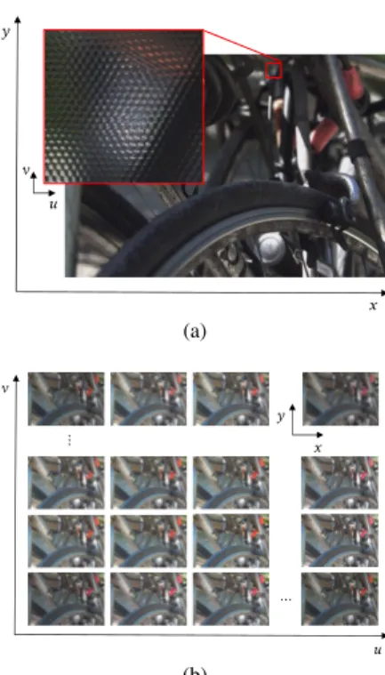
FIGURE 1. The 7D plenoptic function.
in space(x, y, z), toward every possible direction (θ, ϕ), over any range of wavelengths (λ), and at any time (t) — referred to as the plenoptic function (see Fig.1):
P(x, y, z, θ, ϕ, λ, t) (1)
With this definition, it is possible to model different imag-ing systems, includimag-ing the Human eye [32], as samplimag-ings of the 7D plenoptic function in (1). However, due to the enormous amount of data that would be required for sampling using a 7D representation, it is necessary to make reasonable assumptions to reduce the dimensionality of the plenoptic function and to appropriately sample it.
Therefore, Levoy and Hanrahan proposed, in [34], to use the following three assumptions to reduce from the 7D plenoptic function in (1) to a four dimensional (4D) function: 1) Static Scene — Assuming the scene is static, the plenoptic function can be then reduced to
P(x, y, z, θ, ϕ, λ).
2) Constant Radiance along its Path (Free-Space) — With the assumption that the air is truly transparent and the light ray is transmitted in a free-space (i.e., region free of occluders [34]), the plenoptic function can be then represented by its values along an arbitrary selected surface surrounding the scene (see Fig. 1). Hence, the radiance of any light ray in the space can be always obtained by tracing it back to this selected surface. This assumption allows reducing the plenoptic function to P(x, y, θ, ϕ, λ).
3) Trichromatic Human Vision System (HVS) — The Human eye has three types of photosensitive cells (known as cones) in the retina for the perception of colored light. Each of these cone types has its maxi-mum sensitivity in a different wavelength, which cor-responds to the primary colors Red (R), Green (G), and Blue (B). Therefore, it is possible to restrict to the HVS and to reduce the wavelength dimension in (1) by assuming three different plenoptic functions (one for each R, G, and B components). Finally, for each color component, a 4D plenoptic function is defined as
P(x, y, z, θ, ϕ).
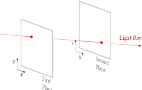
Moreover, it is common to use a two-plane parameteri-zation to represent the 4D plenoptic function in Cartesian coordinates. In this case, and as illustrated in Fig. 2, a spe-cific light ray intersects the first plane at coordinates(x, y), which defines the spatial location of the ray, and it is prop-agated in free-space until it intersects the second plane at
FIGURE 2. Two-plane parameterization for the 4D plenoptic function.
coordinates (u, v), which specifies the propagation direc-tion. Levoy and Hanrahan [34] baptized this 4D function,
L(x, y, u, v), as the 4D light field (a.k.a, lumigraph [33]).
In the context of this paper, it will suffice to describe the complete visible light by this 4D LF function
L(x, y, u, v) [34]. This means that light is here understood
as a scalar radiance (one value for each color component R, G, and B) traveling along straight lines (rays) with different propagation directions. This 4D LF function will be then used to represent a LF image. Additionally, a LF video can also be represented by regularly sampling LF images per unit of time.1Moreover, this paper will particularly focus on reviewing the literature on coding solutions for dense LFs. While a better definition will be given later in the paper, the term dense LF stands for angularly dense LF, and angular density can be understood as the number of viewpoints that are sampled by a LF imaging system in a volume of space. B. OUTLINE
The remainder of this paper is organized as follows. SectionIIbriefly reviews the main stages that are essential for efficiently delivering dense LF content to the end-users, including the recent developments related to LF acquisi-tion, representaacquisi-tion, rendering, display, and visual quality evaluation. SectionIII focuses on the coding requirements and reviews the most relevant coding solutions for dense LF content in the literature, while simultaneously deriving some conclusions and highlighting some of the remaining challenges. Finally, SectionIVconcludes the paper.
II. LIGHT FIELD IMAGING AND PROCESSING
Before concentrating on the LF coding solutions available in the literature, this section provides a brief review on the principles of LF imaging technology and on the main stages that are essential for delivering LF content to end-users.
Essentially, an LF imaging processing chain comprises the following functional stages, as illustrated in Fig.3:
• LF Acquisition/Creation — The first step of the LF processing chain is, naturally, the LF content generation, which can be done through an optical setup or computa-tionally created, i.e., through appropriate modeling and rendering of the visual scene and the acquisition setup.
FIGURE 3. LF imaging processing flow [35].
Therefore, Section II-A reviews the principles of LF imaging acquisition and lists some publicly available LF datasets for LF coding.
• LF Representation — The LF data acquired in the pre-vious stage may or may not be converted to a represen-tation format that is different from the acquired format. In this context, SectionII-Bpresents a brief review of representation formats that have been proposed in the literature.
• LF Coding — Considering the huge amount of data associated to LF transmission systems, efficient LF encoding/decoding solutions become of paramount importance. Since this is the main focus of this paper, SectionII-C presents a brief overview of possible LF coding architectures, and a more detailed survey on LF coding approaches proposed in the literature is presented in SectionIII.
• LF Rendering — Rendering the decoded LF content becomes also an important issue, especially to allow adequate visualization of the decoded LF content in conventional two dimensional (2D) and 3D displays. Therefore, SectionII-Daddresses this issue and reviews some LF rendering algorithms and their capabilities. • LF Display — To take full advantage of the richer
visual information of the acquired LF content, new and more immersive display devices are also needed. For this reason, display technologies have been also evolv-ing in recent years, and Section II-E overviews those developments.
In addition to this, the display technology along with the rendering capabilities will also determine what should be expected in terms of the user experience in LF imaging appli-cations. This fact brings up another challenging issue, which is designing appropriate objective and subjective metrics for LF quality evaluation. This issue is then briefly reviewed in SectionII-F.
A. LF ACQUISITION
With the target of increasing immersion, more advanced imaging technologies are emerging that allow capturing richer forms of visual data and representing the scene by the 4D light field. Different acquisition techniques can be used to capture LF content with different densities in each of the 4D dimensions, depending on the requirements for spatial or angular resolution. Generally, angularly dense LFs allow a smooth transition between viewpoints without the need for view interpolation. Another parameter that may differ depending on the LF capturing system is the Field of
FIGURE 4. Examples of LF acquisition systems: (a) Multi-camera array (From [36]); (b) Camera gantry (From [39]); and (c) Lenslet Camera.
View (FoV) that corresponds to the area of the scene over which objects can be reproduced.
Among the possible techniques for acquiring LFs, three main groups may be listed [14]:
• LF Imaging with Multi-Camera Array — In this case, a number of views with parallax on a single or on both directions (full parallax) is captured using an array of multiple cameras (see Fig. 4a) in a linear [36], circular [2], or even arbitrary arrangement [37]. The spatial density depends on the camera’s sensor resolu-tion and the angular density depends on the distance between the cameras (baseline) on the array. For acquir-ing (angularly) dense LFs, the baseline is usually on the order of millimeters to centimeters [38]; this setup is usually referred to as a High Density Camera Array (HDCA). The FoV that is captured depends on the num-ber of cameras and their optical setup, the baseline and the rotation between the cameras. Usually, the camera array configuration is designed targeting the require-ments of a specific use case scenario. An example of such LF acquisition system is the Stanford multi-camera array proposed in [36], which is composed of 100 cus-tom cameras, and supports reconfigurable arrangement of the array for three different scenarios (i.e., for panoramic video with high dynamic range; for syn-thetic aperture photography; and for widely spaced 3D scenes).
• LF Imaging with Camera Gantry — In this case, a moving camera gantry (see Fig. 4b) is used to capture different viewpoint images at different instants of time. The spatial density depends on the camera’s sensor res-olution and the angular density depends on the accuracy of the gantry motion. The FoV depends on the degrees of freedom that is supported by the gantry structure. Examples of LF camera gantry systems are the Stanford LF gantry [39] and the Fraunhofer robot system [40],
both with four degrees of freedom camera movements (translation along x and y and rotation alongθ and ϕ axes). Although camera gantries provide flexible and lower cost capturing systems, they are restricted for capturing static scenes.
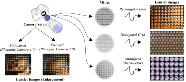
• LF Imaging with Lenslet Camera — In this case, the integral photography concept proposed by Lipp-man [30] is adopted, in which LF content with full parallax can be acquired by using a single-tier sen-sor camera overlaid with a Microlens Array (MLA), as shown in Fig. 4c. The MLA (a.k.a. lenslet array) can be seen as a tiny 2D array of cameras with a very small baseline, sampling the 4D light field and organizing it in a conventional 2D image, known as the lenslet image. As discussed in [41], [42], there are two lenslet camera setups, namely: the unfocused (a.k.a. plenoptic camera 1.0), as used in the commercial Lytro cameras [2], [9]; and the focused (a.k.a. plenoptic camera 2.0), as used in the commercial Raytrix cameras [7]. The difference between these two setups is in the distance b of the MLA to the image sensor (see Fig. 4c). For the unfocused setup, the distance b is equal to the MLA focal length
f (i.e., b = f ), while b 6= f for the focused setup. In practice, varying between these two setups will only change the balance between providing larger angular or spatial density in the captured LF (respectively, using an unfocused or a focused lenslet camera) [41], [43]. In the unfocused lenslet camera, the light of a single ray (or of a thin bundle of rays) from a given angu-lar direction (θ, ϕ) converges on a specific microlens at position (x, y) in the array and is collected at a single pixel position in the image sensor underneath. Hence, the angular density depends on the number of pixels behind each microlens, and the spatial density depends on the number of microlenses in the MLA. In the focused lenslet camera, the closer distance b is to f , the larger is the angular density (and vice-versa). As in a conventional 2D camera, the FoV is defined by the camera’s sensor size and the main lens focal length. Although lenslet cameras can capture highly dense LFs at a single shot, they are specially recommended for capturing objects at small distances due to the their small FoV.
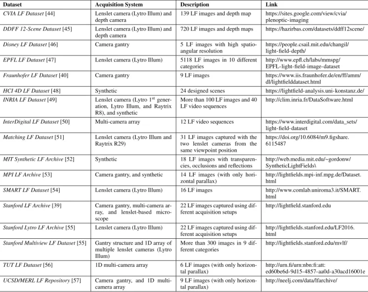
Table 1 presents a list of publicly available datasets for dense LFs in all of the three categories.
It is also possible to combine these techniques to meet some specific requirements for spatial and angular density. For instance, in [55], a gantry structure with a lenslet camera is used for capturing LFs with a baseline varying between micrometers (inside the lenslet camera) to meters (by vary-ing the camera poses). Additionally, in [12], a one dimen-sional (1D) array of GoPro cameras in a vertical arc are placed in a horizontally rotating gantry structure to capture dense LFs with 360◦ FoV. Moreover, depth cameras [58] and Light Detection And Ranging (LIDAR) can also be combined with the above LF techniques to acquire geometry
FIGURE 5. Possible acquired LF representation formats: (a) Lenslet format; and (b) Full parallax multiview format.
information of the scene that may be useful for rendering virtual viewpoints.
B. LF REPRESENTATION
Initially, the data acquired by a LF imaging system can have one of the following (raw) formats [59]:
• Lenslet Representation — For LF acquired using a lenslet camera, the LF content is represented as a 2D image comprising a 2D grid of microlens images (a.k.a. micro-images, elemental images, and macro-pixels), as depicted in Fig.5a.
• Full Parallax Multiview Representation — For LF acquired using a multi-camera array or a camera gantry, the LF content is represented by a 2D grid of views (see Fig. 5b) and, usually, each view has the same spatial resolution.
Although it is possible to adopt these acquisition formats for representing the LF data, in some cases, it may be neces-sary to convert from the acquisition format to a more appro-priate representation format. It is also possible to convert from one to another and, in some cases, this conversion can be invertible or non-invertible, depending on the type of the camera and on the algorithm used [59]–[61].
In fact, a key issue for successful LF imaging applications is the choice of a convenient representation for the LF data acquired, given a certain set of application requirements. If high compression efficiency is a dominant requirement when choosing the LF representation format, then the deci-sion should be made prioritizing a coding perspective, which means that an efficient coded representation should be at the forefront. In this context, this section briefly describes some relevant LF representation formats that have been
TABLE 1. List of publicly available datasets for dense LF content.
proposed in the literature in the context of LF coding. How-ever, it should be noticed that the analysis and discussion of specific LF coded representations performance will be done in SectionIII.
1) LENSLET REPRESENTATION
This representation format corresponds to the raw acquisition format of a lenslet camera and, in this case, no conversion and/or further processing is required. Hence, the LF data is represented as a 2D image comprising a grid of micro-images, as depicted in Fig. 5a. As illustrated in Fig. 6, each micro-image captures a low-resolution portion of the scene. Moreover, several packing schemes, shapes and sizes of microlenses are possible in the array (see Fig. 6), and the structure of these micro-images is a consequence of the chosen MLA. In addition to this, the micro-image charac-teristics may also change depending on the chosen lenslet camera setup (see Fig. 6). For instance, for an unfocused lenslet camera, a micro-image is a picture of the back of the main lens [41] (i.e., it is an image focused on the main
lens), while, for a focused lenslet camera, a micro-image is (a low-resolution portion of) the image of the main lens that is relayed through the microlens.
Analyzing this lenslet representation from a coding point of view, it is observed that, independently of the camera setup or MLA used, the LF content presents some inherent spatial correlations, as illustrated by the autocorrelation function in Fig.7b. Notably, it can be seen that the pixel correlation in a lenslet image is not as smooth as in conventional 2D images (see Fig.7a). Differently, a regular structure of spikes is evi-denced in the autocorrelation function in Fig.7b, in which the constant distance between these regular spikes corresponds to the micro-image spacing in the array. Moreover, as is commonly observed in 2D images (see Fig.7a), pixels inside each micro-image are also significantly correlated within a local neighborhood (see Fig.7b).
2) PSEUDO VIDEO SEQUENCE REPRESENTATION
In this case, viewpoints are stacked together along a pseudo temporal axis to be interpreted as a single Pseudo Video
FIGURE 6. Examples of lenslet images captured using different LF camera setups and MLA structures.
FIGURE 7. Autocorrelation function: (a) 2D image; and (b) Lenslet image.
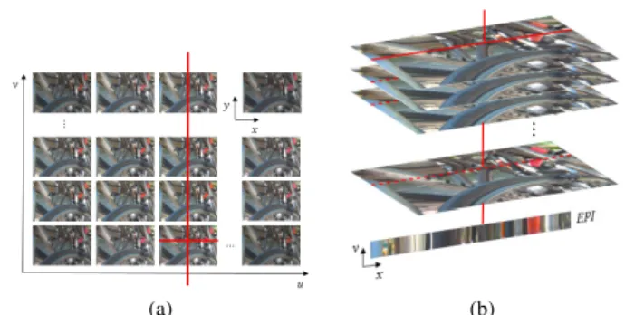
Sequence (PVS), as illustrated in Fig.8b. If the LF acquisition system supports full parallax, the 2D array of viewpoints needs to be scanned using a specific topology to form a 1D array of views, as depicted in Fig. 8a. Some examples of scanning topologies are illustrated in Fig. 9. The (pseudo) temporal correlation varies depending on the scanning topol-ogy used to form the PVS and, consequently, the coding performance will be directly related to this choice.
For representing LF video, the referred to as transposed picture ordering [62] can be used. In this case, all views from the same time instant are concatenated along the time dimension. However, it is worthwhile to note that the tempo-ral correlation between adjacent time instants no longer exists in the final video sequence.
Although for the full parallax multiview acquisition format there is no further pre-processing need prior to coding, for the lenslet acquisition format, it is necessary firstly to convert the lenslet image to a dense array of views. In this context, many approaches have been proposed in the literature for extracting views from a lenslet image:
• Based on Micro-Images — In this case, the lenslet image needs to be firstly split into its multiple micro-images, which are then represented as multiple views with low resolution. For this, further calibra-tion/processing is usually required, for instance: i) to compute the micro-image centers; ii) to compensate
FIGURE 8. PVS representation: (a) Scanning the 2D grid of views in spiral order; and (b) the resulting PVS.
for any potential optical/geometrical distortions that may result in micro-images with different sizes; iii) to deal with non-integer resolutions; and iv) to discard incomplete micro-images (at the border of the lenslet image). Examples of calibration/processing algorithms for lenslet images can be found in [9], [63]. Apart from the process of discarding incomplete micro-images, this calibration/processing can be invertible.
• Based on Subaperture Images — Using the knowl-edge of the exact LF optical setup (e.g., micro-image coordinates and sizes), a subaperture image can be con-structed by extracting one pixel with the same relative position (u, v) from all micro-images. Hence, several low-resolution subaperture images can be extracted at different positions relative to the micro-image center.
FIGURE 9. Possible scan topologies for arranging views: (a) Raster; (b) Serpentine; (c) Perpendicular; (d) Spiral; (e) Zig-zag; (f) Hilbert; (g) U-shape; and (h) Lozenge.
Usually, extracting subaperture images is not straight-forward, needing additional calibration/processing to compute the image centers and to align the micro-image grid to the pixel grid. Moreover, if an MLA with hexagonal grid is used, a transformation is needed to convert from hexagonal to a rectangular MLA grid. Examples of such processing algorithms can be found in [9], [63]. For lenslet images captured using an unfo-cused lenslet camera, each subaperture image repre-sents an in-camera orthographic projection of the cap-tured scene [41]. On the other hand, for lenslet images captured using a focused lenslet camera, a subaperture image (built by taking one pixel from each micro-image) can be seen as a subsampled perspective of the captured scene [64] or as a low resolution rendered view that is focused at infinite [65], [66] which, consequently, presents aliasing artifacts. Alternatives to deal with these aliased views have been proposed in the literature and involve resorting to depth-based rendering [64], [65] or Laplacian-based rendering [67], [68]. In both cases, an increase in the views’ resolution is observed and, consequently, an increase in the LF data size. For this reason, this process to generate views from focused lenslet images is a non-invertible process [59], [60]. • Based on Epipolar Plane Images — In this case,
the LF data can be decomposed according to its light ray distribution by using the Epipolar Plane Image (EPI) technique [69]. Each EPI can be then interpreted as a 2D cut through the captured 4D light field. As an illus-trative example, Fig.10shows an EPI built by stacking together views in the same column (which corresponds to fixing the dimension u, as shown in Fig. 10a) and, then, taking a slice from these views in a particular horizontal plane (by fixing the direction x, as shown in Fig. 10a). A prospective characteristic of this EPI-based representation is that the depth/disparity of the objects can be estimated from the slope of the lines that can be observed in Fig.10b. Examples of this usage can be found in [70]–[72].
3) MULTIVIEW REPRESENTATION
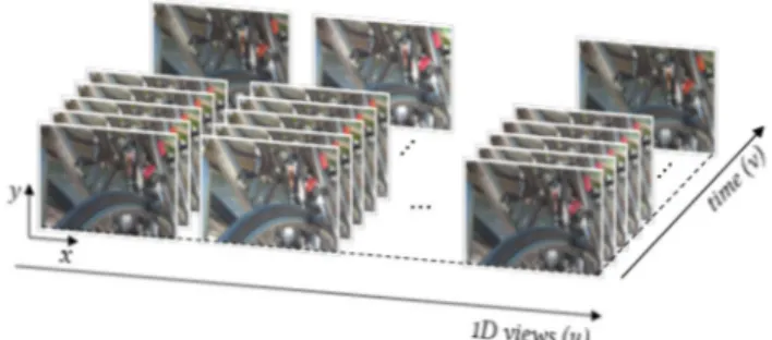
This representation may correspond to the full parallax mul-tiview representation in Fig.5b, in which the 4D LF content is organized as a 2D grid of multiple views. For representing LF videos, a 5D LF representation may be needed. However, revisiting the literature on LF coding, it can be observed that
FIGURE 10. Extracting an EPI from the 4D light field: (a) Fixing the dimensions x and u; and (b) the built EPI.
many of the authors have rather proposed to organize the 4D LF content as a conventional 3D multiview format with only horizontal parallax and to use the temporal axis to comprise the fourth LF dimension, as illustrated in Fig.11. Different to the (single) PVS representation in SectionII-B2, this multi-view representation comprises a 1D array of multiple PVSs. Thus, with this multiview representation, the correlations in an LF image can be exploited in all dimensions — i.e., spatial, inter-view, and (pseudo) temporal. For representing LF videos, the 2D array of viewpoints can be then firstly scanned using a specific topology (see Fig.9) to form the 1D array of multiview videos.
From the full parallax multiview acquisition format there is no further pre-processing need prior to coding. Differently, to convert from the lenslet acquisition format, additional calibration and processing is necessary to compute the micro-image centers, to align the micro-micro-image grid to the pixel grid and possibly a transformation to convert from hexagonal to a rectangular MLA grid, as discussed in SectionII-B2. Then, views can be constructed based on: i) micro-images; ii) subaperture images; or iii) EPIs.
4) VOLUMETRIC REPRESENTATION
In this case, the dense 2D array of viewpoints needs to be scanned using a specific topology (see Fig.9) and stacked together in the third dimension to form a 3D block volume as illustrated in Fig.12. The difference to the PVS representa-tion is on how the LF content is partirepresenta-tioned and processed on the subsequent encoding process. Instead of splitting it into 2D blocks to feed the encoding process, as in the PVS representation, the LF content is split into 3D blocks in the volumetric representation. From this representation, it can be observed that the correlation in the third dimension may
FIGURE 11. Multiview representation constructed using the temporal axis as the fourth dimension.
FIGURE 12. 3D volumetric representation constructed scanning the 2D grid of views in spiral order.
vary depending on the scanning topology used to form the 3D volume.
It should be noticed that the full parallax multiview for-mat in Fig. 5b can also be interpreted as a 4D volumetric representation. This 4D volumetric representation has been also considered in the literature for coding. As discussed in SectionII-B2, to convert from the lenslet acquisition format to this volumetric representation, additional calibration and processing steps are usually necessary to compute the micro-image centers, to align the micro-micro-image grid to the pixel grid, and possibly a transformation to convert from hexagonal to a rectangular MLA grid.
5) GEOMETRY-ASSISTED REPRESENTATION
In this case, the dense LF data is represented by a sparse number of selected key views together with associated geom-etry information as depicted in Fig.13. The geometry infor-mation may comprise, for instance, depth, disparity, or a graph model estimated from the LF data. For lenslet-based LF content, the sparse set of key views may comprise micro-images, subaperture micro-images, or views with higher resolution (for LF content captured by a focused lenslet camera) that are extracted from the LF data.
As geometry information can be used for synthesizing views at the decoder side, the amount of views that needs to be coded and transmitted in the processing chain may be reduced. Consequently, the coding performance of this representation is highly dependent on the selection of the key views and the accuracy of the geometry information estimated from the acquired LF data. Trying to deal with the geometry estimation problem, various depth/disparity
estimation methods [73]–[78] and graph learning models [79]–[81] have been recently proposed in the literature.
C. LF CODING
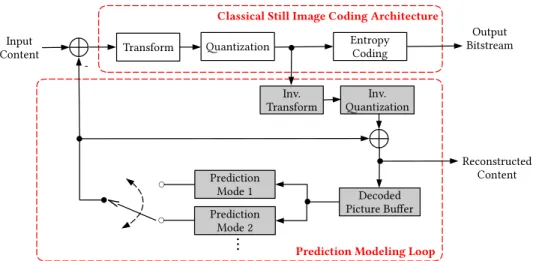
For the earliest LF coding schemes proposed in the literature, the most natural choice has been to use the classical image coding architecture shown in Fig.14 — comprising trans-form, quantization and entropy coding blocks — and to apply an approach that resembles the JPEG [82] or JPEG 2000 [83] standards.
Later, following the advancement of digital multimedia systems and coding technologies, most of the LF image and video coding frameworks in the literature have been based on a hybrid coding architecture due to its effective-ness for providing high efficiency compression. Currently, the most successful class of visual coding architectures are based on this framework [84], which has been adopted in most 2D video coding standards, including the state-of-the-art HEVC [85] and the future video coding standard Versatile Video Coding (VVC) [86], which has been developed in a joint collaboration effort known as the Joint Video Explo-ration Team (JVET) between ITU-T Video Coding Experts Group (VCEG) and ISO/IEC MPEG. This model is called hybrid as it combines the advantages of using a transform coding stage from classical still image coding solutions with a prediction modeling loop (see Fig.14), in which a prediction signal is generated from information available at both encoder and decoder sides. The block diagram of a conventional hybrid encoder is illustrated in Fig. 14 and comprises the following functional blocks:
• Prediction Modeling — The prediction modeling aims at reducing the redundancy by exploiting the inherent correlations of the input content. Usually, in a hybrid video coder, a prediction may be formed by using spa-tially neighboring samples — known as intra predic-tion — or by using neighboring frames — known as inter prediction. Instead of coding the original pixels values of the current block, only the difference between current and prediction block, called residual block, is encoded and transmitted. In inter-prediction, a motion compen-sated prediction is used for modeling the translational moving blocks in different frames. In this case, a dis-placement vector — known as motion vector — is used to indicate the horizontal and vertical positions (relative to the current block position) of the prediction block inside a previously encoded reference picture. Tradi-tionally, inter prediction was designed for exploiting the redundancy between neighboring temporal frames, however, it can actually be generalized to other types of redundancy (e.g., inter-view prediction and non-local spatial prediction as will be seen later on in this paper). • Transform — The goal of transform coding (see Fig. 14) is to convert the residual block into the fre-quency domain such that it has a representation that is both decorrelated — i.e., separated into components
FIGURE 13. Geometry-assisted representation, comprising a sparse set of key views plus geometry information.
FIGURE 14. Block-diagram of a conventional hybrid video encoder. Built-in decoder is shown in gray shaded blocks.
FIGURE 15. Multiview video coding architecture.
with minimal inter dependence — and compact — i.e., where most of the energy is concentrated into a small number of values. The most effective and widely used transform in image and video coders is the 2D Discrete Cosine Transform (DCT). However, JPEG 2000 [83] and MPEG 4 Visual [87] standards have also adopted the 2D Discrete Wavelet Transform (DWT). The output of this process is a transform block with the same size as the residual block, representing the image in the frequency domain. At the decoder side, an inverse transform is
used to reverse the operation and reconstruct the residual block in spatial domain.
• Quantization — Quantization (see Fig.14) is applied to the transformed coefficients. The quantizer is designed to discard insignificant values, such as near-zero coef-ficients, while preserving a small number of significant non-zero coefficients. In this process, the quantization step is used to regulate the range of the quantized values and consequently the output bit rate (or average bits per pixel in the case of still pictures).
• Entropy Coding — The small number of signifi-cant coefficients, as well the prediction parameters (e.g., quantized residual block, and motion vectors), are entropy coded to remove statistical redundancy. Among the various possible entropy coders in the literature, Context-based Arithmetic Binary Coding (CABAC) has shown to be a powerful method for providing a high degree of adaptation and redundancy reduction. For this reason, the state-of-the-art HEVC standard has also adopted CABAC-based entropy coding. In a nutshell, CABAC starts with a binarization process in which the entries are transformed to binary symbols (bins). For each bin, a suitable context model is then selected depending on the statistics of recently coded bins.
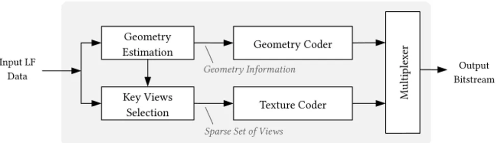
FIGURE 16. Geometry-assisted LF coding architecture.
Thus, each bin is arithmetic coded according to the selected context model. The output of this process is the compressed bitstream, which can then be stored or transmitted.
The encoder duplicates the decoder process to guarantee that they both generate identical predictions for subsequent frames (see shaded gray blocks in Fig.14).
Instead of using a 2D video codec, some LF coding solu-tions have adopted a multiview video coding architecture as illustrated in Fig. 15, such as the one used in the HEVC multiview extension MV-HEVC [88]. The basic idea in these multiview video coding solutions is to exploit not only the redundancies that exist temporally between the frames within a given view, but also the redundancies between frames of neighboring views — known as inter-view prediction. In this case, a multilayer approach is used where different 2D video coded representations, called layers, are multiplexed into one bitstream. In MV-HEVC, a layer simply represents the texture data belonging to the same camera perspective (i.e., a view). In the first layer, usually denoted as the base layer, the pictures are coded independently from other layers. The layers that follow the base layer are denoted as enhancement layers. In these enhancement layers, inter prediction methods are used for both inter-view and temporal motion prediction by making the decoded pictures from other views also available as reference pictures.
Mainly motivated by the design of recent 3D coding solu-tions, such as 3D HEVC [88], geometry-assisted LF coding architectures have been also proposed in the literature for LF coding. In this case, the geometry-assisted representation format (see SectionII-B5) is adopted in order to achieve com-pression. As illustrated in Fig.16, a sparse set of key-views is selected from the LF data and encoded with a texture coder, which may be a 2D video coder (see Fig.14) or a multiview video coder (see Fig.15) solution. The geometry information estimated from the LF data is usually independently coded from the texture data by a dedicated geometry coder (see Fig.16). Afterwards, data from both coders are multiplexed into one bitstream. At the decoder side, additional intermedi-ate views are synthesized by using a specific view synthesis technique, as it will be seen in SectionIII-D.
D. LF RENDERING
While traditional 2D and 3D decoded content may be directly forwarded to the display stage without much processing,
decoded LF content requires, typically, an appropriate render-ing algorithm to be visualized, for instance, in conventional 2D/3D displays or in more advanced HMD and LF displays. In this context, one important requirement for the design of LF rendering algorithms is to offer the best end-user experience targeting a specific display technology. Moreover, this requirement may eventually consider not only the visual quality of the rendered content, but also the level of user interaction that is enabled.
In this sense, among the advantages of the LF imaging technology is the ability to open new degrees of freedom in terms of content rendering, supporting post-production func-tionalities not straightforwardly available using conventional 2D and 3D systems, such as:
• Perspective Shift — Changing the perspective of the recorded scene can be obtained by simply switching between the captured dense array of views, or by re-tracing and interpolating light rays as they come from a virtual perspective camera at an arbitrary position, generating a virtual viewpoint [33], [89], [90]. The vir-tual camera can be positioned along the camera path or can be from within the captured scene - referred to as z-rendering and step-in/out effect [91].
• Refocusing — Refocus can be understood as virtu-ally sliding the camera focus plane to a different plane (within the captured depth range). In its basic form, this operation can be obtained by aligning the views at a particular depth plane and integrating them over the directional axis [89]. Therefore, objects that are at the chosen depth plane appear in sharp focus in the rendered view, while the remaining objects are blurred. It is pos-sible to select multiple depth planes to be in focus and to create an all in-focus rendered view. Some relevant algorithms proposed in the literature for refocusing can be found in [41], [65], [89], [92]–[94].
• Depth-of-Field Control (Synthetic Aperture) — Extending or narrowing the depth-of-field in the ren-dered view can be obtained by defining greater or smaller depth ranges where scene objects are rendered in focus. This capability emulates the effect of changing the aperture size in conventional photography where larger apertures produce images with shallower depth-of-field, and with smaller apertures more of the scene appears in focus. As discussed in [89], an arbitrary synthetic aperture size can be obtained when rendering a view by
choosing more or less views to be integrated over the directional axis. The shape of the synthetic aperture and, consequently, the bokeh in the rendered view can also be controlled by weighting differently the samples from each view [89].
• Super-Resolution — It is possible to take advantage of the full potential of the LF information to apply super-resolution either in the spatial or in the angular dimensions. LF spatial super-resolution typically uses depth information, estimated from the LF data, to super-resolve a view by propagating light rays intensity values from neighboring views to sub-pixel positions, as pro-posed in [64], [66], [95]. Angular super-resolution is typ-ically used to synthesize virtual viewpoints from a small set of views, as proposed in [96]–[98]. View synthesis algorithms proposed in the literature for compression purposes will be seen in SectionIII-D.
• Distance Measurement — If the optical properties of the LF system are known precisely, it is possible to translate the relative estimated depth data into absolute distance from the lens, as proposed in [99]–[101]. • Dooly-Zoom (Vertigo Effect) — This effect is used
to make a subject in the foreground remain in a rela-tively static position while the background compresses or stretches. This capability can be accomplished by combining a virtual zoom out/in with a step-in/out effect [102].
E. LF DISPLAY
Naturally, since LF imaging systems allow recording the 4D light field, the LF content can be more easily played in a wider variety of display technologies by simply re-creating different displayable versions of the same LF content. In this context, among the possible display technologies that are currently available for LF content visualization, one can cite:
• 2D Displays — In this case, a single 2D view, or more specifically, a 2D version of the LF content must be rendered from the decoded LF content.
• Stereo Displays — In this case, a pair of views need to be rendered from the lenslet image and delivered to the display. This type of display technology allows then improving the user’s depth perception (with respect to the 2D display) by presenting a different view to his/her left and right eyes (typically, by means of a pair of eyeglasses).
• Multiview Autostereoscopic Displays — Multiview Autostereoscopic is a glassless display technology that allows creating a more natural 3D illusion (with respect to the stereo display) to the end-user by presenting a different perspective as the user moves horizontally around the display (known as horizontal motion paral-lax). In this case, multiple views need to be rendered from the LF content and delivered to the display. Moreover, following the recent developments in sen-sor and optical manufacturing, the display technologies are also evolving for providing a more natural and
immersive visualization. Therefore, some prospective display technologies have also started to show up. Among them, it is possible to cite:
• AR and VR Displays — AR and VR HMD allow the user to see different perspectives as he/she moves through the scene. In the case of an AR HMD, the real environment is seen through half-transparent mirrors and then virtual 2D views are seamlessly blended into the real scene [1], [103]. In the case of a VR HMD, a large number of virtual 2D views are delivered to the HMD for providing to the user the impression of immer-sion in a real environment. Some AR and VR solutions have proposed to take advantage of a microlens-based [1], [104] or a mirror-microlens-based [105] LF imaging technology for creating a more natural visualization in AR and VR HMDs.
• LF Displays — A display technology using an optical setup similar to the one used in lenslet cameras can be also designed for LF visualization, as proposed by Nippon H¯os¯o Ky¯okai (NHK) Japan Broadcast Corpo-ration [3]. Another LF display technology uses a very dense number of views to create a replica of the 4D light field, as proposed by Holografika [4], Ostendo [8], and Looking Glass Factory [106].
F. LF QUALITY EVALUATION
A new challenging research topic is also to assess the visual quality as perceived by end-users after processing and com-pressing LF content. Visual quality assessment is generally carried out by determining suitable objective and subjective evaluation techniques.
Among objective quality metrics, Peak Signal to Noise Ratio (PSNR) and the Structural Similarity Index (SSIM) [107] have been the most commonly used metrics to assess the visual quality of 2D image and video under compression distortions. In the context of LF content, JPEG Pleno [108] and MPEG-I [59] have also adopted these met-rics in core experiments. In this case, PSNR and SSIM are calculated per view for all color components and the average over all viewpoint positions is adopted as an overall quality measure. Apart from this, there have been only a few works specifically addressing objective quality assessment metrics for LF content. In [109], a sparse angle-dependent and a sparse depth-dependent metric are proposed. In the sparse angle-dependent metric, the average SSIM is taken in a set of five views from equidistant viewing angles. In the sparse depth-dependent, depth information is estimated and the average PSNR is taken in a rendered view (with fixed angular position) over sets of pixels in different depth layers. In [110], a quality evaluation method based on contrast and gradient measurements is proposed that measure the impact of LF compression in the visual quality by measuring the amount of compression blur in rendered views. In [111], a no-reference metric is proposed to quantify the amount of distortion due to LF rendering based on the number of light rays per unit area of the scene that is used to estimate an unknown
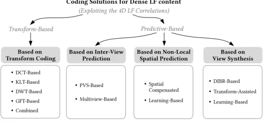
FIGURE 17. The LF coding solutions in the literature are grouped into four categories (in shaded gray blocks).
light ray. In [112], an objective metric that combines a spatial component and an angular component is proposed to evaluate the visual quality of 3D content on light field displays.
Following the standardization initiatives of JPEG Pleno and MPEG-I, methodologies for subjectively assessing the visual quality of LF content have also started being addressed in the literature. In [23], a methodology is proposed for visu-ally evaluating compressed Lytro Illum lenslet images using a conventional 2D display and Double Stimulus Continuous Quality Scale (DSCQS) metric [113]. In [114], a method-ology as well as prototype software for performing subjec-tive quality assessment of compressed Lytro Illum lenslet images is proposed that aims at designing a methodology that enables global assessment of quality of experience in a flexible and interactive way [114]. In [115], a LF dataset for quality evaluation is proposed (see Table1) and an analysis of the subjective quality of compressed LF image is presented. In [54], an analysis of the impact of different visualization techniques — i.e., image-based and animated-based visual-ization of rendered views in a 2D display — on the obtained scores in subjective quality evaluation is presented. In [116], an analysis of how light field subsampling affects the per-ceived quality of refocused views visualized in an animated fashion is presented. In [53], a subjective evaluation on a 3D monitor with head tracking is performed to assess the performance of various objective quality metrics on distorted LF contents. In [117], a subject evaluation on a light field display [4] is performed aiming at analyzing the correlation between spatial and angular resolution and discussing ways to improve parallax perception.
III. LITERATURE REVIEW ON DENSE LIGHT FIELD CODING
After reviewing the most relevant aspects of LF imaging and processing in the previous section, it is then possible to better characterize the existing LF coding approaches in the literature. To facilitate this, the various LF coding approaches
are clustered into the two major classes depicted in Fig.17, by identifying which functional part of the codec is responsi-ble for exploiting the inherent LF correlations. Notably:
• Transform-Based Approaches — As its name sug-gests, transform-based approaches exploit the LF cor-relations in the transform domain, based on a particular transform coding technique. LF coding solutions in this class are reviewed in SectionIII-A.
• Predictive-Based Approaches — Differently, predic-tive based approaches exploit the LF correlations in a predictive manner. As illustrated in Fig. 17, pre-dictive based approaches can be further categorized depending on the particular data format and prediction schemes adopted. Notably, three categories are identi-fied: i) LF coding based on inter-view prediction, which is reviewed in SectionIII-B; ii) LF coding based on non-local spatial prediction, reviewed in SectionIII-C; and, finally, iii) LF coding based on view synthesis, reviewed in SectionIII-D.
Although transform and predictive based approaches appear separated from each other in Fig.17, it does not mean that a transform based approach excludes completely any type of predictive coding tool from its architecture (or vice versa). For instance, a predictive based approach may use a hybrid coding architecture, as seen in SectionII-C.
It is worth mentioning that, the evaluation procedures and the coding conditions are usually divergent among different publications, which makes it difficult a straightforward com-parison between distinct LF coding solutions in the literature. Nevertheless, when discussing about the performance of each LF coding solution presented, an effort was made to include some quantitative results in terms of bit savings as long as it was available in the original publication (alternatively, coding gains in decibel (dB) are presented). Additionally, at the end of each section, a level discussion is provided to high-light the most relevant results, advantages, and limitations of the LF coding solutions in each category.
A. TRANSFORM-BASED LF CODING
Starting with transform based approaches, these correspond to LF coding solutions that rely on transform coding for exploiting the inherent LF correlations. Specifically, various transform coding techniques can be used to decorrelate the LF image and then remove the redundant information between neighboring views. Therefore, it is possible to group the transform based approaches into five categories, depending on the type of used transform (see Fig. 17): i) Discrete Cosine Transform (DCT)-based; ii) Discrete Wavelet Trans-form (DWT)-based; iii) Karhunen Loève TransTrans-form (KLT)-based; iv) Graph Fourier Transform (GFT)-(KLT)-based; and v) combined approaches.
These approaches have been mainly proposed for lenslet LF coding. In this case, the lenslet image undergoes a pre-processing operation to convert it to the volumetric represen-tation format presented in SectionII-B4. Therefore, not only the existing spatial redundancy within each view is exploited, but also the redundancy between neighboring views. 1) DCT-BASED CODING
Inspired by the approach adopted by JPEG standard, the LF coding schemes in this group make use of the classical image coding architecture shown in Fig.14, but to apply a 3D or 4D version of the DCT transform.
In [118], a DCT-based coding solution is proposed for lenticular-based imaging [119], where a 1D cylindrical MLA is used for capturing instead of the 2D array of microlenses. The lenslet image is organized into stacks of 8 adjacent micro-images and the 3D DCT is applied to each 8×8×8 block. Then, the resulting DCT coefficients are uniformly quan-tized and both DC and AC quanquan-tized coefficients are equally entropy coded by using a combination of run-length and Huffman coding. It is shown that the proposed solution presents significant improvements compared to JPEG for gray-level lenslet images. In [120], further improvements in compression performance are achieved by using an alter-native quantization strategy. In [121], the solution with the 3D DCT from [118] is generalized for lenslet LF with full parallax. In this case, both the horizontal and vertical micro-images are decorrelated simultaneously by the 3D DCT. Hence, it is shown that different scan ordering approaches for gathering the horizontal and vertical micro-images (to form 8×8×8 stacks) result in different Rate-Distortion (RD) performances. This fact has motivated the work in [122], which proposes to use a Hilbert space-filling curve (see Fig. 9f) for scanning the micro-images in the array and forming 8×8×8 stacks to be 3D DCT coded. Various scan-ning topologies are compared, namely: raster, perpendicular and spiral (see Fig. 9) and it is shown that the 3D DCT in conjunction with the Hilbert scan outperforms all other tested solutions. In addition, an adaptive 3D DCT based framework is proposed in [123], in which the number of micro-images involved in a single 3D DCT is varied (between 8×8×1, 8×8×2, 8×8×4, and 8×8×8 stacks of micro-images) according to the micro-image cross correlation in
a neighborhood. In this case, the micro-image mean values are used as a measure of correlation between micro-images. Consequently, it is shown that the adaptive 3D DCT could significantly outperform the non adaptive solution from [118] (for lenticular-based images). An alternative adaptive 3D DCT-based approach has been proposed in [124]. Similarly to [123], the mean value is used as a correlation metric. However, the 3D DCT is applied to stacks of subaperture images and the size of the 3D DCT is varied between 16×16×16 down to 4×4×4, depending on the correlation between neighboring subaperture images. From this, it is shown that further improvements can be achieved compared to the adaptive solution proposed in [123] (when also applied to subaperture images).
More recently, a lenslet LF coding approach using a 4D DCT is proposed in [125] and referred to as Multidimensional Light Field Encoder (MuLE). To explore the 4D redundancy of LFs, the lenslet image is converted to its full-parallax multiview format (see Fig. 5b) and it is divided into 4D blocks (with two spatial plus two directional dimensions) and a separable 1D DCT is applied to each dimension. Then, the resulting DCT coefficients are grouped into bitplanes and processed by an hexadeca-tree coder to cluster zero coef-ficients into 16 4D subregions — referred to as hexadeca tree partition [125]. Both the hexadeca-tree bits and the bits from the significant coefficients are entropy coded using an adaptive arithmetic coder. This solution is compared against a PVS-based solution in which all subaperture images are scanned in serpentine order (see Fig. 9b) to be coded using HEVC and VP9 codecs, and against a LF solution based on JPEG 2000 and view synthesis proposed in [126] (see Section III-D1. Compared against the PVS-based HEVC solution for coding lenslet images from the EPFL LF Dataset (see Table1), the MuLE achieves, in average, 38.1% of bit savings, while the view synthesis solution in [126] achieves 36.4 % of bit savings, and the PVS-based VP9 solution achieves 20.5% of bit savings. This solution has been recently adopted in the JPEG Pleno Verification Model (VM) [127] (since version 2.0) for lenslet LF coding.
2) KLT-BASED CODING
Instead of using the DCT as in the previous section, other schemes propose to use a KLT-based approach for LF cod-ing. The KLT — a.k.a. Principal Components Analysis (PCA) [128] decomposition and Hotelling [129] transform — is a block based transform that exploits the statistical charac-teristics of the input data. The KLT consists of decomposing the input data in a set of orthonormal basis functions (known as the principal components) into which the variance of the input data is maximal. This corresponds to ordering the eigen-vectors of the covariance matrix (the KLT matrix), which is calculated with the input data, according to the largest eigenvalues.
The idea of applying the KLT transform for compres-sion comes from the fact that a linear combination of any reduced number, k, of eigenvectors corresponds to the best
FIGURE 18. KLT-based LF image coding schemes: (a) Proposed by Jang, Yeom, and Javidi [131]; and (b) Proposed by Kang, Shin, and
Kim [133], [134].
approximation of the input data in a reduced k-dimension subspace (i.e., the approximation with minimal mean square error) [130]. Therefore, different compression ratios can be achieved by simply discarding less (or more) eigenvectors (i.e., discarding rows from the covariance matrix). Concern-ing the usage of KLT for image compression, although the KLT is very efficient in compacting the energy in a small number of eigenvectors, there are still some implementation related difficulties, mainly due to the fact that the KLT basis functions are image dependent. However, it may be suitable in applications where the statistics of the data change slowly and the covariance matrix is kept small [130].
Regarding LF coding, a KLT-based coding scheme is proposed in [131] for lenslet LF coding, in which a Vector Quantization (VQ) scheme is used for clustering different micro-images into a representative set of vectors to be then coded with KLT, as illustrated in Fig.18a. For this, the lenslet image is divided into consecutive blocks of d × d samples which are treated as a (d × d )-dimensional vector. These vectors are then grouped into S different classes by using the Linde-Buzo-Gray (LBG) optimization algorithm [132]. As a result, a codebook is derived, consisting of S representative vectors (known as code vectors). Then, a KLT with (k × k)-dimension is applied into the vectors from each of the S classes so as to reduce the dimensionality of their vectors from (d × d ) to (k × k)-dimension vectors, where k ≤ d . Afterwards, the reduced KLT coefficients, together with the codebook and the KLT matrix, are scaled and rounded to the nearest integer to compose the output bitstream. From the presented results, it is shown that varying the d × d block size does not affect the RD efficiency for lenslet image coding. However, the larger the number of sets S, the better is the observed RD performance. Moreover, the presented KLT scheme always outperforms the JPEG standard for lower bit rates.
An alternative KLT-based coding scheme is also proposed in [133], [134], as illustrated in Fig. 18b. In this case, the lenslet image is decomposed into its subaperture images, which are then KLT coded. It is worth noting that there is
no further information on how the resulting KLT coefficients together with the KLT matrix are coded and transmitted in [133], [134]. It is shown that this approach achieves better RD performance compared to JPEG and the same KLT based approach applied to micro-images. In addition, it is observed that the statistical characteristics between subaperture images are more easily decorrelated than between micro-images, having most of the relevant information compacted into a smaller number of eigenvectors. As stated in [134], due to the small FoV of the microlenses in the array, each captured micro-image comprises only a small portion of the 3D scene, which may have different characteristics in different areas of the 3D scene. On the contrary, all subaperture images com-prise the complete 3D scene, which are only slightly different on the angles of projection. Consequently, LF redundancy is considerably larger in subaperture images than in micro-images.
3) DWT-BASED CODING
In alternative to block-based transforms, such as the DCT and KLT, some authors proposed to use an approach based on DWT coding, closer to the coding techniques used in JPEG 2000 codecs [83].
In [135], a 3D DWT-based coding scheme is proposed for lenslet LF coding following the classical still image coding architecture illustrated in Fig.14. For this, the lenslet image is firstly decomposed into a stack of subaperture images and a separate 1D DWT is recursively applied in the third dimen-sion of this stack until the lowest frequency subband contains only two samples (in the third dimension). Then, a two level 2D DWT decomposition is applied to these two sets of lowest frequency bands. Similarly to JPEG 2000, the lowest fre-quency subbands are quantized using a deadzone quantizer, while the remaining high frequency coefficients are quantized using a uniform scalar quantizer. Following this, a new scan-ning pattern is proposed to be used to scan samples from all subbands together, which are then arithmetic coded.
In [136], a similar approach with a 3D DWT applied to a stack of subaperture images is proposed. However, in this case, the three (separable) 1D DWTs are recursively applied to each dimension of the stack, producing 8 subbands in each decomposition level. Afterwards, the 3D DWT coefficients are quantized using a deadzone scalar quantizer and coded using the method of Set Partitioning In Hierarchical Trees (SPIHT) [137]. Similarly to the Embedded Block Coding with Optimal Truncation (EBCOT) [138], used in JPEG 2000, the SPIHT algorithm is used as a form of entropy coding applied to bitplanes of quantized coefficients to allow pro-gressive transmission of the LF data. The proposed approach is compared to a 2D version of the coding scheme, in which a 2D DWT is applied to the entire lenslet image followed by SPIHT. The 3D DWT scheme presents significant improve-ments compared to the 2D DWT. Moreover, several DWT bank filters are analyzed for the 3D DWT coding, and the Biorthogonal 2.2 filters show the best results, but are very similar to the Daubechies filters. In [139], a 4D DWT-based
FIGURE 19. 1D DWT lifting structure.
scheme is proposed for coding LF acquired with multi-camera arrays. For this, a separable 1D DWT is applied to each of 4D dimensions of a LF data. The obtained 4D DWT coefficients are then coded by using SPIHT [137].
Regarding standard DWT based coding solutions, a study on lenslet image coding is presented in [140], in which the performance of two DWT based coding solutions (JPEG 2000 and SPIHT) and one DCT based standard solu-tion (JPEG) are compared. The performance is analyzed in terms of the objective quality of views rendered from the coded and reconstructed lenslet image, by using aver-age PSNR and averaver-age SSIM index. It is shown that the SPIHT scheme presents better RD performance than JPEG for low bit rates, but JPEG 2000 outperforms them both for either PSNR or SSIM metrics. In [141], a similar study is performed for comparing two standard solutions, JPEG 2000 and JPEG XR [142], for lenslet image coding. This study focuses on comparing the performance, in terms of objective quality of rendered views, of the different transform coding solutions used in each standard, namely: the JPEG 2000 DWT and the block-based DCT transform used in JPEG XR [142]. In the presented results, JPEG 2000 achieves slightly better RD performance than JPEG XR both in terms of PSNR and SSIM metrics. In addition, an empirical per-formance analysis is presented in [143] for synthetic lenslet images. For this, JPEG 2000 is compared to its exten-sion for volumetric data compresexten-sion — JPEG 2000 Part 10 [144], known as JP3D — for lenslet image compres-sion. The JP3D solution supports 3D DWT decompositions and extends tiles, code-blocks and Region of Interest (ROI) functionalities accordingly to support volumetric data. In the presented study [143], JPEG 2000 is applied to the entire lenslet image, while two different scenarios are considered for JP3D, in which the 3D DWT is applied to stacks of micro-images, and to stacks of subaperture images. It is shown that the JP3D solution outperforms the JPEG 2000 for both scenarios.
In [145], a 4D DWT scheme is proposed for coding LF captured with a multi-camera array. Firstly, a 2D lifting-based Haar DWT [146] is carried out by applying a 1D DWT lifting structure horizontally and vertically across the 2D array of views. As depicted in Fig.19, estimated disparity information is used in the prediction and update steps of the 1D DWT lifting structure to exploit the inter-view correlation. For this, the views are divided into two interlaced sets of even and odd views. In the prediction step, the disparity information is used to predict an odd view by warping it from an even view. Then, the resulting prediction residual from the
odd view corresponds to the high frequency subband of the Haar DWT. Afterwards, in the update step, this high fre-quency subband is then warped and added to the even view to generate the low frequency subband, which is approx-imately the disparity compensated average between even and odd views. After this 2D inter-view transform, a multi-level 2D DWT is applied to each frequency subband images. To encode the transformed coefficients, a modified SPIHT algorithm is adopted to work in a block-wise manner. It is worth mentioning that this coding architecture supports view scalability by progressively decoding the interview frequency subbands. Moreover, the number of scalable layers can vary by applying more or less decomposition levels in the inter-view DWT. Motivated by this fact, a scalable lenslet LF cod-ing scheme based on DWT liftcod-ing is proposed in [147]. In this scheme, the disparity information is derived by matching a set of SIFT descriptors extracted from two different subaper-ture images and estimating the corresponding homography transform. Then, the resulting homography matrix is trans-mitted to the decoder side. Similarly to [145], a 2D lifting-based Haar DWT is applied to exploit inter-view correlation. Afterwards, the inter-view frequency subband images are coded using JPEG 2000 coder. Experimental results for cod-ing lenslet images from the EPFL LF Dataset (see Table1) show that it is possible to reach, in average, 62.85% and 78.80% of bit savings compared to coding each subaperture image independently using JPEG 2000 and JPEG, respec-tively. In [148], a lifting-based DWT scheme is also pro-posed for coding LFs captured with a multi-camera array. Similarly to [147], the DWT subband images are coded using JPEG 2000. However, in this case, the views are divided into Groups of Views (GOV) and the disparity is coded for only one reference view from each GOV. For this, an anchored disparity modeling is proposed for representing the disparity data and a backfilling methodology is proposed for deriving disparity relationships in disoccluded areas. Then, the dis-parity data in reference views are coded using a break point adaptative DWT with 5 levels of decomposition followed by EBCOT. Experimental results are presented for coding LF images from the Fraunhofer LF Dataset (see Table1), which compare the proposed solution against a PVS-based solution with serpentine ordering (see Fig. 9b) and HEVC. It should be noticed that, in these experiments, only a subsampled set of views are coded with the proposed scheme and the remaining views are interpolated using the 4 nearest coded views. The results show a superior performance of the proposed solution, achieving gains of 2 dB and 3–4 dB, respectively, at high and low bit rates.
4) GFT-BASED CODING
Graph signal processing has proved to be a powerful tool for modeling irregular structures and the complex interac-tions among them [149]. Notably, the GFT allows extending the notions of classical Fourier transform to signal sam-ples indexed by nodes of an arbitrary directed or undirected graph. A graph is commonly defined as a mathematical
![FIGURE 3. LF imaging processing flow [35].](https://thumb-eu.123doks.com/thumbv2/123dok_br/18378901.892281/4.864.437.794.102.386/figure-lf-imaging-processing-flow.webp)