DUAL-BAND IMPLANTABLE ANTENNAS FOR MEDI-CAL TELEMETRY: A FAST DESIGN METHODOLOGY AND VALIDATION FOR INTRA-CRANIAL PRESSURE MONITORING
Asimina Kiourti1, *, Konstantinos A. Psathas1,
Jorge R. Costa2, 3, Carlos A. Fernandes2, 4,
and Konstantina S. Nikita1
1School of Electrical and Computer Engineering, National Technical
University of Athens, Athens, Greece
2Instituto de Telecomunicac˜oes, Lisboa, Portugal
3Departamento de Ciˆencias e Tecnologias da Informac˜ao, Instituto
Universit´ario de Lisboa (ISCTE-IUL), Lisboa, Portugal
4Instituto Superior T´ecnico, Technical University of Lisbon, Portugal
Abstract—In this study, we suggest and experimentally validate a methodology for fast and optimized design of dual-band implantable antennas for medical telemetry (MICS, 402–405 MHz, and ISM, 2400–2480 MHz). The methodology aims to adjust the design of a parametric dual-band antenna model towards optimally satisfying the requirements imposed by the antenna-fabrication procedure and medical application in hand. Design is performed in a systematic, fast, and accurate way. To demonstrate its effectiveness, the proposed methodology is applied to optimize the parametric antenna model for intra-cranial pressure (ICP) monitoring given a specific antenna-fabrication procedure. For validation purposes, a prototype of the optimized antenna is fabricated and experimentally tested. The proposed antenna is further evaluated within a 13-tissue anatomical head model in terms of resonance, radiation, and safety performance for ICP monitoring. Extensive parametric studies of the optimized antenna are, finally, performed. Feasibility of the proposed parametric antenna model to be optimally re-adjusted for various scenarios is demonstrated, and generic guidelines are provided for implantable antenna design. Dual-band operation is targeted to ensure energy
Received 17 May 2013, Accepted 6 July 2013, Scheduled 12 July 2013
autonomy for the implant. Finite Element (FE) and Finite Difference Time Domain (FDTD) simulations are carried out in homogeneous rectangular and anatomical head tissue models, respectively.
1. INTRODUCTION
Implantable Medical Devices (IMDs) may be used as sensors [1, 2], nerve stimulators [3, 4] or drug delivery devices [5], and are nowadays attracting significant scientific interest for medical prevention, diagnosis, and treatment. A key component of an IMD is the implantable antenna, i.e., the antenna which is integrated into the IMD to ensure its (bi-directional) telemetry with exterior monitoring/control equipment. The Medical Implant Communications Service (MICS) band (402–405 MHz) is most commonly used for medical implant telemetry, because of its advantages to be internationally available and feasible with low power circuits, reliably support high data rate transmissions, fall within a relatively low noise portion of the spectrum, and propagate acceptably through human tissue [6]. Nevertheless, the Industrial, Scientific and Medical (ISM) bands of 433, 915, 2450 and 5800 MHz are also used in some studies [7]. Patch antennas are generally preferred for IMDs, because of their flexibility in design, conformability, and shape [8]. Implantable antenna design is highly demanding, with two of the major challenges being miniaturization and low-power consumption.
Given the fact that implantable antennas are intended for operation inside the human body, miniaturization proves to be one of their most important features. Dimensions of the traditional half-wavelength or quarter-wavelength antennas in the MICS band make them useless for implantable applications. Human tissue in which implantable antennas are intended to operate exhibits high permittivity, which works to advantageously reduce their size. However, additional miniaturization techniques are solicited for further shrinking the occupied volume of implantable antennas. For example, common miniaturization techniques for implantable patch antennas include meandering/spiraling of the conducting patch [9], short-circuiting of the patch with the ground plane [10], and vertical stacking of multiple radiating patches [11].
Another challenge of implantable antenna design is the energy efficiency of the IMD, or, equivalently, its ability for long-term operation. Elimination of medical surgeries for replacing the battery of the IMD, as well as avoidance of regular battery recharges through inductive coupling techniques [12] could drastically improve the quality of life for patients with IMDs. In an attempt to increase the
energy autonomy of the implant, dual-band implantable antennas have recently been proposed in the literature [13–15]. Such antennas provide an innovative “sleep and wake-up” communication link between the IMD and exterior monitoring/control equipment: an exterior “wake-up” signal is sent to the IMD in one operation band (ISM band of 2400–2480 MHz), and, once the system “wakes-up”, medical data is transmitted in the other operation band (MICS band). Use of the ISM band enables an extremely low average sleep current, which further improves the power efficiency of the IMD [16].
In this paper, we propose a three-step design methodology for fast and accurate design of dual-band implantable antennas (MICS and 2450 MHz ISM). The methodology aims to optimally adjust the design of a parametric dual-band implantable antenna model according to the requirements imposed by the antenna-fabrication procedure and medical application in hand. Effectiveness is demonstrated by applying the proposed methodology to design an optimized dual-band implantable antenna for intra-cranial pressure (ICP) monitoring [11, 17, 18] given a specific antenna-fabrication procedure. For validation purposes, a prototype of the optimized antenna is fabricated and experimentally tested. The proposed antenna is further evaluated within a 13-tissue anatomical head model in terms of resonance, radiation, and safety performance for ICP monitoring. An extensive parametric study of the optimized antenna is, finally, performed. The goal is to demonstrate the feasibility of the proposed parametric antenna model to be optimally re-adjusted for various scenarios, and provide generic guidelines for implantable antenna design. The paper is organized as follows: Section 2 describes the proposed parametric antenna model and design methodology. Numerical and experimental results for ICP monitoring are presented in Section 3. The paper concludes in Section 4.
2. PROPOSED ANTENNA MODEL AND DESIGN METHODOLOGY
2.1. Parametric Antenna Model
A parametric model of a dual-band implantable patch antenna is proposed, as shown in Fig. 1 (MICS and 2450 MHz ISM). Circular shape is suggested for eliminating sharp edges which may hurt the surrounding biological tissues during implantation. From bottom to top (Fig. 1(a)), the antenna consists of a ground plane, a dielectric substrate layer, a meandered patch plane, a glue layer, and a dielectric superstrate layer. Patch meandering (Fig. 1(b)) increases the length of the current flow, thus decreasing the physical size of the antenna [9],
while addition of a superstrate layer preserves the biocompatibility of the structure [8]. In actual applications, the antenna will be mounted on a biocompatible medical device, which will also serve as its ground plane. Glue is used to bond the substrate and superstrate layers together. A shorting pin (S) connects the meandered patch to the ground plane in order to increase the electrical length of the antenna and further miniaturize its size [10]. The structure is fed by a 50-Ohm coaxial cable (F ), which allows for “proof-of-concept” experimental testing. However, in actual applications, there will be a direct connection between the implantable antenna and the integrated circuit of the medical device under consideration. Throughout this study, the origin of the coordinate system is located at the center of the antenna ground plane, as shown in Fig. 1.
In an attempt to provide a generic antenna model with a high number of degrees of freedom, the model has been extensively parameterized to include 25 design parameters, which can be summarized as follows:
• Size of the antenna [6 parameters], as determined (directly or
indirectly) by the antenna’s diameter (D), relative permittivity of the substrate and superstrate dielectric material (εrd), relative permittivity of the bonding glue (εrg), and thickness of the
substrate (hsub), superstrate (hsup), and glue (hg) layers. To avoid
direct contact of the copper patch with the surrounding biological tissues, while still maintaining an increased radiating surface area, the radius of the patch is selected to be 0.1 mm smaller than D/2.
• Shape of the patch [15 parameters], as determined by the slots’
positions (Pi, i = 1 − 4), lengths (li, i = 1 − 4) and widths (wi, i = 1 − 4), and the variable cuts LA, LB and LC, as shown in
Fig. 1(b).
• Position of the coaxial feed and shorting pin [4 parameters], as
determined by their x and y coordinates, i.e., F : (Fx, Fy) and S:
(Sx, Sy).
Within the framework of this study, the aforementioned design parameters are grouped into two categories, namely (a) the “fabrication-specific” and (b) the “to-be-optimized” parameters. “Fabrication-specific” parameters are determined by the antenna designer based on the fabrication procedure in hand (materials, assembling tools, and technical expertise/experience) and the intended antenna dimensions (set by both the fabrication procedure and the desired implantation site of the antenna). These include the parameters related to the size of the antenna (first 6 parameters). Once the “fabrication-specific” parameter values have been selected, the “to-be-optimized” parameters are evaluated for optimized resonance in the
desired operation bands. These include the parameters related to the shape of the patch, as well as the positions of the coaxial feed and shorting pin (last 19 parameters).
Interconnections and restrictions between the antenna design parameters are given by Eqs. (1)–(9): Eqs. (1)–(5) restrict the position and size of the slots within the limits of the patch, Eqs. (6)–(7) restrict the position of the shorting pin (S) within the patch and in between the slots marked as 2 and 3 (Fig. 1(b)), while Eqs. (8)–(9) confine the position of the coaxial feed (F ) within the patch and in between the slots marked as 3 and 4 (Fig. 1(b)).
li< 2 · q (D/2)2−P2i, i = 1 − 4 (1) P1−w21+LA<D2 (2) P4−w24+LB<D2 (3) Pi+ wi 2 < Pi+1− wi+1 2 , i = 1 − 3 (4) LC< l4 (5) P2+w22< Sx< P3−w23 (6) Sy< ¯ ¯ ¯ ¯ q (D/2)2−S2x ¯ ¯ ¯ ¯ (7) (a) (b)
Figure 1. Proposed parametric antenna model: (a) side (zx plane) and (b) top (xy plane) views.
P3+w23< Fx< P4−w24 (8) Fy< ¯ ¯ ¯ ¯ q (D/2)2−F2x ¯ ¯ ¯ ¯ (9)
Even though circular shape has been preferred for antenna design, as justified above, the proposed parametric antenna model can easily be modified for square or rectangular shape. For example, the dual-band implantable antennas which have been proposed for glucose-monitoring in [13, 14] can be considered as rectangular variations of the proposed parametric antenna model. However, as compared to previous dual-band implantable antenna designs which have been proposed in the literature [13–15], the proposed antenna model exhibits four major advantages: (a) implant-friendly shape (circular), (b) potential for miniaturized occupied volume, as dictated by the selected parameter values, (c) inclusion of a glue-layer which allows fine-tuning of the antenna for any fabrication procedure in hand, and (d) increased flexibility in design thanks to the high number of degrees of freedom, which may be effective or not, according to the designer’s choice. 2.2. Design Methodology
A systematic, three-step, methodology is proposed for fast and optimized design of dual-band implantable antennas (MICS and 2450 MHz ISM), as shown in Fig. 2. The goal is to quickly adjust antenna design in order to optimally suit the requirements of the fabrication procedure and medical application in hand. The methodology is described step-by-step within the framework of optimizing the multi-parametric antenna model of Fig. 1. However, it is important to highlight that the methodology can be generalized and applied to any dual-band implantable antenna model, as long as the designer parameterizes it, and properly groups its design parameters into “fabrication-specific” and “to-be-optimized”, as shown in Section 2.1.
In the first step, the values of the “fabrication-specific” antenna parameters are determined, i.e., antenna diameter (D), permittivity of the dielectric (εrd) and glue (εrg) materials, and thickness of the substrate (hsub), superstrate (hsup), and glue (hg) layers. Requirements of the application under consideration and limitations imposed by the antenna fabrication procedure in hand provide direct footage to the designer as guidance for such design decisions. This is considered to be an important input to the second step of the methodology given the fact that different “fabrication-specific” antenna parameters are expected to result in highly different antenna designs. It is worth
Figure 2. Flow chart of the proposed fast methodology for optimized design of dual-band (MICS and ISM) implantable antennas. In the first step, “fabrication-specific” parameters are determined based on the antenna fabrication procedure in hand and the intended antenna dimensions. In the second step, the “to-be-optimized” parameters are modified to obtain an “initial antenna” design, which achieves satisfactory resonance performance (|S11@MICS,ISM| < −10 dB). In the
third step, the “optimized antenna” design is derived, which exhibits optimized resonance performance ((|S11@MICS,ISM| = min).
noting that gluing parameters (εrg and hg) are the most critical ones: the low-permittivity glue layer isolates the high-permittivity substrate layers, thus decreasing the effective dielectric constant and electrical length of the antenna, while increasing its resonance frequency.
In the second step, an initial version of the antenna (“Initial Antenna”) is obtained. The “to-be-optimized” parameters are initialized to random values which fall within the restrictions imposed by Eqs. (1)–(9) (“Random Antenna”), and the antenna is placed at a distance d under the outer surface of the tissue-box shown
(a) (b)
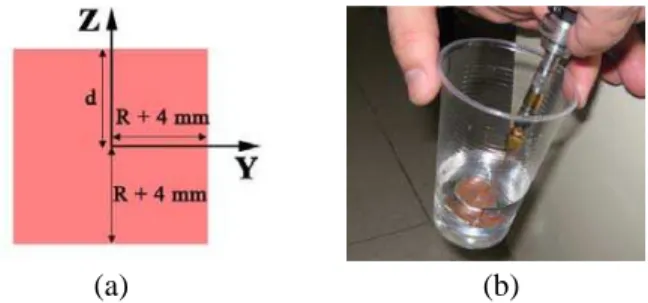
Figure 3. (a) Tissue-box used in the proposed dual-band antenna design methodology, and (b) equivalent phantom used for experimental validation.
in Fig. 3(a) [19]. The tissue-simulating box extends by R + 4 mm in the x- and y-directions (R = D/2 is the maximum dimension of the antenna in the positive x-axis) and simulates the dielectric properties (permittivity, εr, and conductivity, σ) of the intended
implantation tissue. The distance d corresponds to the actual air-to-antenna separation distance for the desired medical application (implantation depth). This set-up optimally takes into account the effect of the surrounding tissues and exterior air on the implantable antenna given a specific medical application scenario, as indicated by the authors in [19]. Furthermore, simulations inside such a small tissue box are significantly faster, as compared to those inside canonical or anatomical tissue models of the intended implantation site [19]. The “to-be-optimized” parameters are subsequently manually updated in an iterative way until the magnitude of the reflection coefficient (|S11|)
in the MICS (402 MHz) and ISM (2450 MHz) bands conforms to:
|S11@MICS,ISM| < −10 dB (10) Manual update relies on the skills and expertise of the designer, who is considered to be aware of the theoretical background related to antenna miniaturization (e.g., longer meanders are expected to increase the length of the current flow and result in lower resonance frequencies, etc.). It is worth noting that, in the unlikely case, in which the condition of Eq. (10) cannot (or is hard to) be satisfied in a reasonable number of manual iterations, then the “fabrication-specific” parameters can be re-defined, by returning back to the first step of the methodology.
In the third step, the optimized antenna design is derived (“Optimized Antenna”). Quasi-Newton optimization is performed due to its speed and accuracy in cases of insignificant numerical noise [20]. The “fabrication-specific” parameters are kept fixed to those of the “Initial Antenna”, while the “to-be-optimized” parameters
are considered as dimensions in the solution space. The optimization process terminates when:
|S11@MICS,ISM| = min (11)
or when the number of iterations exceeds 300. Optimization is performed inside the tissue-box of Fig. 3(a). Setting the “initial antenna” of the second step as input to this third step is considered to be of utmost importance. The optimization algorithm would not be able to converge in any reasonable number of iterations if the “to-be-optimized” parameters were set to random values instead of being initialized to the values of the “initial antenna”.
Tissue dielectric properties at 402 and 2450 MHz are suggested to be approximated as constant inside the 300–500 MHz and 2300– 2600 MHz ranges, respectively. Equivalently, different tissue models are suggested for each operation frequency band of the antenna. Tissue models with frequency-dependent dielectric properties would be more realistic, but would significantly slow down the simulations. This approach is remarkably faster, yet still reliable and accurate, as indicated by the authors in [11, 21].
3. NUMERICAL AND EXPERIMENTAL RESULTS 3.1. Antenna Design for ICP Monitoring
In an attempt to demonstrate its effectiveness, the proposed three-step design methodology is applied to design a novel dual-band implantable antenna for ICP monitoring applications [11, 17, 18]. The antenna model is implanted at a distance of d = 3 mm under the outer surface of the tissue-box of Fig. 3(a), which corresponds to the actual average implantation depth inside the human scalp. Since the antenna is intended for scalp (simulated as skin-tissue) implantation, the tissue-box is considered to represent skin-tissue dielectric properties at 402 and 2450 MHz for operation in the MICS and ISM bands, respectively (Table 1) [22–24]. This is achieved by setting frequency-dependent dielectric properties for the skin-tissue simulating material. In other words, a single skin-box is considered in the simulations, whose dielectric properties depend upon frequency according to a set of data points, which are specified by the designer to suit the corresponding theoretical values (Table 1) [22–24]. Size of the skin-box varies according to the maximum dimension of the antenna under study (R = D/2, where D is the diameter of the antenna according to Fig. 1(a)) [19]. Finite Element (FE) simulations are carried out in Ansoft HFSS [25]. The FE solver performs iterative tetrahedron-meshing refinement automatically, with the mesh being perturbed by
Table 1. Dielectric properties (relative permittivity, εr, conductivity,
σ (S/m)) and mass densities of the tissues used in this study [22–24].
Tissue 402 MHz 2450 MHz Mass Density
(kg/m3) εr σ εr σ Skin 46.74 0.69 38.01 1.46 1100 Bone 13.14 0.09 11.38 0.39 2200 Dura 46.65 0.83 42.04 1.67 1100 CSF 70.97 2.25 66.24 3.46 1020 Grey Matter 57.40 0.74 48.91 1.81 1030 White Matter 42.05 0.45 36.17 1.22 1030 Muscle 57.11 0.80 52.73 1.74 1040 Cartilage 45.45 0.59 38.77 1.76 1100 Vitreous Humor 69.00 1.53 68.21 2.48 1000 Lens 48.14 0.67 44.63 1.50 1100 Eye Sclera 57.66 1.00 52.63 2.03 1100 Spinal Cord 35.39 0.45 30.15 1.09 1040 Cerebellum 55.94 1.03 44.80 2.10 1030
30% between each iterative pass. The mesh refinement procedure stops when the maximum change in the magnitude of the reflection coefficient between two consecutive passes is less than 0.02 or when the number of passes exceeds 10.
In the first step of the methodology, the “fabrication-specific” parameters are determined for the antenna. As a compromise between antenna miniaturization and exhibited radiation performance [26], and given the diameter of the available cutter tools to be used for prototype fabrication, the diameter of the antenna is set to D = 24 mm. Rogers RO3210 dielectric is used for the substrate and superstrate layers, because it exhibits high permittivity (εrd = 10.2) which facilitates miniaturization. Thickness of the dielectric layers is set to hsub =
hsup = 0.635 mm, as dictated by the Rogers RO3210 sheets which are available in our lab, and our intention for miniature antenna size. A low-permittivity glue (εrg = 4.5) is selected, which has been found
to strongly bond the dielectric layers together, while exhibiting a small thickness of hg = 0.08 mm. Values of the “fabrication-specific”
parameters are summarized in Table 2.
In the second step, the “to-be-optimized” parameters are randomly selected, as shown in Table 2 (“Random Antenna”). Manual update of the “to-be-optimized” parameters results in the values of
Table 2. Values of the “fabrication-specific” and “to-be-optimized” parameters of the proposed “Random Antenna”, “Initial Antenna”, and “Optimized Antenna” for ICP monitoring.
Parameters “Random Antenna” “Initial Antenna” “Optimized Antenna” “fabrication-specific” D 24.0 mm 24 mm 24.0 mm hsub 0.635 mm 0.635 mm 0.635 mm hg 0.08 mm 0.08 mm 0.08 mm hsup 0.635 mm 0.635 mm 0.635 mm εrd 10.2 10.2 10.2 εrg 4.5 4.5 4.5 “to-be-optimized” P1 −6.0 mm −4.5 mm −3.9 mm P2 −2.0 mm −1.7 mm −1.6 mm P3 2.0 mm 2.0 mm 2.4 mm P4 6.0 mm 5.6 mm 5.5 mm w1 1.0 mm 1.3 mm 0.7 mm w2 1.0 mm 0.3 mm 0.7 mm w3 1.0 mm 1.4 mm 2.3 mm w4 1.0 mm 1.9 mm 0.6 mm l1 15.0 mm 17.7 mm 20.9 mm l2 15.0 mm 15.3 mm 20.8 mm l3 15.0 mm 18.0 mm 18.9 mm l4 15.0 mm 19.5 mm 9.9 mm LA 0.0 mm 0.0 mm 6.6 mm LB 0.0 mm 3.4 mm 6.3 mm LC 0.0 mm 10.7 mm 7.4 mm
Table 2 (“Initial Antenna”), which form a dual-band implantable antenna design that satisfies Eq. (10).
In the third step, the “to-be-optimized” parameters are optimized based on Quasi-Newton optimization. The optimization algorithm performed 99 iterations to result in the optimized parameters of Table 2 (“Optimized Antenna”) which minimize the cost function of Eq. (11). This translates to approximately 360 min of total simulation time in a mid-range PC with an i5 3470 processor (3rd gen.) and 8 GB of installed RAM, running Windows 8 Professional (x64). Having in mind that each optimization step involves solving of the geometry at both 402 MHz (∼1.50 min simulation time per step) and 2450 MHz (2.10 min simulation time per step), the occurring simulation time is considered to be relatively short [19]. Compared to 402 MHz, the
(a) (b)
Figure 4. Proposed dual-band implantable “Optimized Antenna” for ICP monitoring: (a) numerical model and (b) fabricated prototype.
MICS band ISM band
-30 -25 -20 -15 -10 -5 0 300 350 400 450 500 Refl. Coeff. [dB] Frequency [MHz] simulation measurement -30 -25 -20 -15 -10 -5 0 2300 2400 2500 2600 Refl. Coeff. (dB) Frequency (MHz) simulation measurement (a) (b)
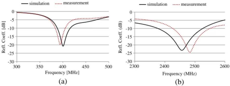
Figure 5. Simulated and measured reflection coefficient frequency re-sponses of the proposed dual-band implantable “Optimized Antenna” for ICP monitoring: (a) MICS band and (b) ISM band.
increased simulation time required at 2450 MHz can be attributed to the higher operating frequency, which, in turn requires a more detailed mesh to solve. The top (xy plane) view of the patch of the resulting “Optimized Antenna” is shown in Fig. 4(a). Traces of the coaxial feed (F ) and shorting pin (S) are also depicted. The reflection coefficient frequency response of the “Optimized Antenna” is indicated in Fig. 5(a) (solid line). Dual resonances are achieved in the MICS (402 MHz) and ISM (2450 MHz) bands, with wide 10 dB bandwidths of 30 MHz and 151 MHz, respectively.
3.2. Experimental Validation of the Proposed Antenna for ICP Monitoring
For validation purposes, a prototype of the proposed dual-band implantable “Optimized Antenna” for ICP monitoring is fabricated and experimentally tested. Two liquids are initially formulated to emulate skin-tissue properties at 402 MHz (deionized water 41.49%,
sugar 56.18%, NaCl 2.33%) and 2450 MHz (deionized water 47.00%, sugar 53.00%), respectively [13]. The phantom is a typical plastic drinking glass (lower diameter of 55 mm, upper diameter of 75 mm, height of 110 mm), semi-filled with each of the skin-emulating liquids, as shown in Fig. 3(b). The aim is to emulate the skin-tissue simulating box of Fig. 3(a). A prototype of the proposed “Optimized Antenna” is then fabricated (Fig. 4(b)), and integrated on an EZ-47 coaxial cable for feeding purposes. The prototype is further connected to a network analyzer and immersed at a distance of approximately d = 3 mm from the bottom of each of the phantoms. The measured reflection coefficient frequency responses at the frequency bands of interest are shown in Fig. 5 (dotted line). Insignificant changes were observed when the antenna was moved transversely inside the phantoms at the same height. Good agreement exists between experimental and numerical results; slight discrepancies are only observed which are within the uncertainty range imposed by fabrication and in-vitro testing inaccuracies.
3.3. Antenna Performance for ICP Monitoring
In order to provide realistic results for ICP monitoring applications, the proposed “Optimized Antenna” (Fig. 4(a)) is implanted inside
(a)
MICS band ISM band
-30 -25 -20 -15 -10 -5 0 300 350 400 450 500 Refl. Coeff. [dB] Frequency [MHz] head (XFDTD) box (HFSS) -30 -25 -20 -15 -10 -5 0 2300 2400 2500 2600 Refl. Coeff. [dB] Frequency [MHz] head (XFDTD) box (HFSS) (b)
402 MHz 2450 MHz
(c)
402 MHz 2450 MHz
(d)
Figure 6. (a) 13-tissue anatomical head model used for verifying the performance of the proposed dual-band implantable “ptimized Antenna” for ICP monitoring, and exhibited (b) resonance, (c) radiation (far-field gain radiation patterns), and (d) safety (local SAR distributions for the zy-slices where maximum local SAR values are recorded) performance (net-input power of 7.66 mW).
the scalp (simulated as skin-tissue) of a 13-tissue anatomical head model (Fig.6(a)), and numerically evaluated in terms of the exhibited resonance, radiation and safety performance. Antenna implantation is performed at a distance of d = 3 mm under the outer surface of the head model, so that the coordinate systems of Fig. 4(a) and Fig. 6(a) coincide. Finite Difference Time Domain (FDTD) simulations are carried out in Remcom XFDTD [27], which enables efficient modeling of anatomical body parts. The antenna and anatomical head are modeled in 0.08 and 3.66 mm-edge cubic cells, respectively. Meshing is adaptive to avoid abrupt transitions. Tissue types, dielectric properties at 402 MHz (MICS band) and 2450 MHz (ISM band) [22–24] and mass densities are indicated in Table 1.
The calculated reflection coefficient frequency responses of the antenna are shown in Fig. 6(b) (solid line). The antenna resonates at 415 MHz (MICS band) and 2460 MHz (ISM band) with 10
dB-bandwidths of 27 MHz and 74 MHz, respectively. Simulation results of Fig. 5(a) are super-imposed for comparison purposes (dotted line). Detuning and reflection coefficient degradation issues for implantable antennas inside specific anatomical locations have been discussed by the authors in [11, 28]. The antenna radiates asymmetrical far-field gain radiation patterns while implanted in the head model (Fig. 6(c)), with the maximum far-field gain values calculated as −30.0 dB and
−10.1 dB at 402 and 2450 MHz, respectively.
Asymmetry is attributed to the asymmetrical loading of the antenna by the surrounding tissues and the exterior air, while relatively low gain values are observed because of the miniature antenna size and high tissue loss. Maximum 1 g-averaged (SAR1 g) and 10 g-averaged
(SAR10 g) Specific Absorption Rate (SAR) values at 402 MHz equal
208.24 W/kg and 50.48 W/kg, respectively, for a net-input power of 1 W. The respective values at 2450 MHz equal 164.72 W/kg and 48.70 W/kg, respectively. Therefore, the IEEE C95.1-1999 safety standard (SAR1 g ≤ 1.6 W/kg) limits the maximum allowed net-input
power to 7.66 mW (MICS band) and 9.71 mW (ISM band) [29]. The recent IEEE C95.1-2005 safety standard (SAR10 g ≤ 2 W/kg) occurs
to be less strict, limiting the respective net-input power levels to 39.62 mW (MICS band) and 41.07 mW (ISM band) [30]. Local SAR distributions at 402 and 2450 MHz are shown in Fig. 6(d) for a net-input power of 7.66 mW. The zy-plane slices of maximum local SAR are depicted.
The effects of head properties (anatomy and dielectric parameters) on the resonance, radiation, and safety performance of scalp-implantable antennas have been investigated by the authors in [28]. Detuning and impedance mismatch issues for implantable antennas caused by variations in the dielectric parameters of body tissues and different anatomical distributions have also been quantified in [31]. 3.4. Parametric Study of the Antenna Design
A parametric study is hereafter performed regarding the effect of the slots’ length and width, materials of the dielectric layers and bonding glue, and thickness of the substrate, superstrate and glue layers, on the resonance performance of the proposed “Optimized PIFA” for ICP monitoring (Fig. 4(a)). The parameters being studied are identified as those which have the greatest influence on the impedance matching of the antenna, and their effects on: (a) the exhibited resonance frequencies in the MICS and ISM bands (fres), and (b) the reflection
coefficient magnitude at these frequencies are recorded. Numerical simulations are carried out inside the skin-tissue simulating box of Fig. 3(a). The aim is to provide a thorough understanding of the
working principles of the proposed parametric antenna model (Fig. 1), and demonstrate its feasibility to be adjusted to any fabrication procedure and medical application that the designer may have in hand. Even beyond the parametric antenna model of this study, the parametric results can prove useful to the design and fine-tuning of any implantable antenna.
3.4.1. Effect of the Slots’ Length and Width
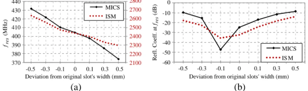
The lengths (li, i = 1 − 4) and widths (wi, i = 1 − 4) of the slots which assist in meandering the conducting patch of the antenna are parametrically studied. Initially, the lengths of the slots are simultaneously varied by the same amount (Fig. 7) while preserving their original widths (Table 2, “Optimized Antenna”). Subsequently, the widths of the slots are simultaneously varied by the same amount (Fig. 8) while preserving their original lengths (Table 2, “Optimized PIFA”). Longer and wider meanders increase the length of the effective
2100 2200 2300 2400 2500 2600 2700 2800 370 380 390 400 410 420 430 440 -1 -0.6 -0.2 0 0.2 0.6 1 fres (MHz)
Deviation from original slots' length (mm) MICS ISM -60 -50 -40 -30 -20 -10 0 -1 -0.6 -0.2 0 0.2 0.6 1 Refl. Coeff. at fres (d B)
Deviation from original slots' length (mm) MICS ISM
(a) (b)
Figure 7. Effect of the slots’ lengths on: (a) the antenna resonance frequencies (fres) and (b) the exhibited reflection coefficient at these
frequencies. 2100 2200 2300 2400 2500 2600 2700 2800 370 380 390 400 410 420 430 440 -0.5 -0.3 -0.1 0 0.1 0.3 0.5 fres (MHz)
Deviation from original slot's width (mm) MICS ISM -0.5 -0.3 -0.1 0 0.1 0.3 0.5 Refl. Coeff. at fres (dB)
Deviation from original slots' width (mm) MICS IS M (a) (b) -60 -50 -40 -30 -20 -10 0
Figure 8. Effect of the slots’ widths on: (a) the antenna resonance frequencies (fres) and (b) the exhibited reflection coefficient at these
current path on the meandered patch, increasing, in turn, the effective size of the antenna. As a result, the resonance frequency of the antenna in both operation bands (MICS and ISM) is decreased (Fig. 7(a), Fig. 8(a)). Assuming that the antenna works properly when the value of the reflection coefficient at the intended operation frequency is less than −10 dB, it becomes evident from Fig. 7(b) and Fig. 8(b) that significantly shorter/longer or narrower/wider meanders could end up in a non-functional dual-band antenna. Further design modifications would, thus, be required in order to refine tuning.
3.4.2. Effect of the Dielectric and Glue Materials
In order to assess the effect of the dielectric material on the exhibited resonance performance, the following dielectric materials are evaluated in the place of Rogers RO3210 (εrd = 10.2): Teflon (εrd = 2.1), Rogers RO3206 (εrd = 6.15), and alumina 98% (εrd = 9.8). As for
(a) (b)
Figure 9. Effect of dielectric material on: (a) the antenna resonance frequencies (fres) and (b) the exhibited reflection coefficient at these
frequencies. 2100 2200 2300 2400 2500 2600 2700 2800 370 380 390 400 410 420 430 440 fres (MHz)
Glue dielectric constant (ε rg) MICS ISM -60 -50 -40 -30 -20 -10 0 Refl. Coeff. at f res (dB)
Glue dielectric constant (εrg)
MICS ISM 8 7 6 5 4 3 2 1 1 2 3 4 5 6 7 8 (a) (b)
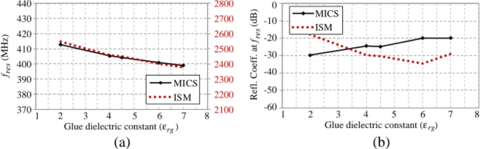
Figure 10. Effect of glue material on: (a) the antenna resonance frequencies (fres) and (b) the exhibited reflection coefficient at these
the bonding glue, deviations of ±2.5 are considered from its original permittivity value (εrg = 4.5). For comparison purposes, thicknesses of the substrate, superstrate, and glue layers are kept fixed to those of the original design (Table 2, “Optimized Antenna”). Materials with higher dielectric constants shorten the antenna’s wavelength, increase its electrical length and are, thus, found to decrease its resonance frequency (Fig. 9(a), Fig. 10(a)). Adequate resonance performance of the antenna is achieved only when the dielectric or glue materials are to be substituted with corresponding materials of highly similar permittivities (Fig. 9(b), Fig. 10(b)).
3.4.3. Effect of the Superstrate, Glue and Substrate Thicknesses
Thickness of the superstrate (hsup), glue (hg) and substrate (hsub)
layers alters the loading effect of the high-permittivity tissue material
2100 2200 2300 2400 2500 2600 2700 370 380 390 400 410 420 430 440 0.2 0.4 0.6 0.635 0.8 1.2 fres (MHz)
Superstrate layer thickness (hsup) (mm)
MICS ISM -60 -50 -40 -30 -20 -10 0 0.2 0.4 0.6 0.635 0.8 1 1.2 Refl. Coeff. at fres (dB)
Superstrate layer thickness (hsup) (mm)
MICS ISM
(a) (b)
1
Figure 11. Effect of the substrate layer thickness (hsup) on (a) the antenna resonance frequencies (fres) and (b) the exhibited reflection
coefficient at these frequencies (fres).
2100 2200 2300 2400 2500 2600 2700 2800 370 380 390 400 410 420 430 440 0.04 0.08 0.14 0.24 0.34 0.44 0.54 0.64 fres (MHz)
Glue layer thickness (hg) (mm) MICS ISM -60 -50 -40 -30 -20 -10 0 0.04 0.08 0.14 0.24 0.34 0.44 0.54 0.64 Refl. Coeff. at fres (d B)
Glue layer thickness (hg) (mm) MICS ISM
(a) (b)
Figure 12. Effect of the glue layer thickness (hg) on (a) the antenna resonance frequencies (fres) and (b) the exhibited reflection coefficient at these frequencies (fres).
on the antenna, thus substantially affecting its effective dielectric constant. More specifically, thicker dielectric layers are expected to isolate the antenna from the high-permittivity skin-tissue, thus decreasing its effective dielectric constant and electrical length, while increasing its resonance frequencies. This is indeed the case in Fig. 11(a) and Fig. 12(a) where changes in the superstrate and glue layer thicknesses are considered, respectively. Modifying the thickness of the substrate layer also affects the shorting pin-related resonance effect, overall resulting in lower resonance frequencies for thicker substrates in the ISM band, as indicated in Fig. 13(a). Thin layers can assist in drastically decreasing the size of the antenna, though careful design modifications would further be required for adequate resonance performance (Fig. 11(b), Fig. 12(b), Fig. 13(b)).
2100 2200 2300 2400 2500 2600 2700 2800 370 380 390 400 410 420 430 440 0.2 0.4 0.6 0.635 0.8 1 1.2 fres (M Hz )
Substrate layer thickness (hsub) (mm)
MICS ISM -60 -50 -40 -30 -20 -10 0 0.2 0.4 0.6 0.635 0.8 1.2 Refl. Coeff. at fres (dB)
Substrate layer thickness (hsub) (mm) MICS ISM
1
(a) (b)
Figure 13. Effect of the substrate layer thickness (hsub) on (a) the antenna resonance frequencies (fres) and (b) the exhibited reflection
coefficient at these frequencies (fres).
4. SUMMARY AND CONCLUSIONS
In this paper, a fast, three-step, methodology was proposed for the design of dual-band (MICS and 2450 MHz ISM) implantable antennas which optimally suit the requirements and limitations of the antenna fabrication procedure and medical application in hand. The methodology involves a dual-band implantable antenna model, which has been extensively parameterized (25 design parameters) to provide a high number of degrees of freedom in the design. The dual-band design philosophy is considered in an attempt to provide a significant boost to the energy autonomy of the IMD. As compared to previously reported dual-band implantable antennas, the proposed antenna model exhibits: (a) implant-friendly shape (circular), (b) potential for miniaturized occupied volume, as dictated by the selected parameter values, (c) inclusion of a glue-layer which allows fine-tuning of the antenna for any fabrication procedure in hand, and (d) increased
flexibility in design thanks to the high number of degrees of freedom. To demonstrate their effectiveness, the proposed design method-ology and dual-band antenna model were applied to design an opti-mized dual-band implantable antenna for ICP monitoring. For val-idation purposes, a prototype of this proposed antenna was fabri-cated and experimentally tested, with the experimental versus numer-ical results showing quite good agreement. Resonance, radiation and safety performance of the designed antenna was further evaluated in-side a 13-tissue anatomical head model, demonstrating adequate char-acteristics for ICP monitoring (bandwidth of 27 MHz (402 MHz) and 74 MHz (2450 MHz), maximum far-field gain of −30.0 dB (402 MHz) and −10.1 dB (2450 MHz), maximum allowable net-input power im-posed by the IEEE C95.1-1999 standard of 7.66 mW (402 MHz) and 9.71 mW (2450 MHz), and maximum allowable net-input power im-posed by the IEEE C95.1-2005 standard of 39.62 mW (402 MHz) and 41.07 mW (2450 MHz)).
Finally, an extensive parametric study was performed related to the effect of the most crucial design parameters of the aforementioned optimized antenna. The aim was to demonstrate feasibility of the proposed antenna model to adjust to any fabrication procedure and medical application in hand, by applying the proposed three-step design methodology. Further beyond the dual-band antenna model of this study, parametric results provide a significant guidance for the design and fine-tuning of any implantable antenna.
ACKNOWLEDGMENT
The authors would like to thank C. Brito and A. Almeida for prototype fabrication and measurement, as well as Prof. L. Alc´acer and his group for phantom formulation (Instituto de Telecomunicac˜oes, Lisbon, Portugal). This work has been supported by the COST VISTA (IC1102) Action and the Operational Programme “Education and Lifelong Learning”, co-financed by the European Union (European Social Fund — ESF) and national funds, under the project ARISTEIA DEM-II-MED (“Implantable and Ingestible Medical Devices (IIMDs): Optimal-Performance-Oriented Design and Evaluation Methodology”). The work of A. K. was supported by the IEEE Microwave Theory and Techniques Society Graduate Fellowship for Medical Applications.
REFERENCES
1. Shults, M. C., R. K. Rhodes, S. J. Updike, B. J. Gilligan, and W. N. Reining, “A telemetry-instrumentation system for monitoring multiple subcutaneously implanted glucose sensors,”
IEEE Transactions on Biomedical Engineering, Vol. 41, No. 10,
937–942, 1994.
2. Noroozi, Z. and F. Hojjat-Kashani, “Three-dimensional FDTD analysis of the dual-band implantable antenna for continuous glucose monitoring,” Progress In Electromagnetics Research
Letters, Vol. 28, 9–21, 2012.
3. Guillory, K. S. and R. A. Normann, “A 100-channel system for real time detection and storage of extracellular spike waveforms,”
Journal of Neuroscience Methods, Vol. 91, Nos. 1–2, 21–29, 1999.
4. Permana, H., Q. Fang, and W. S. T. Rowe, “Hermetic implantable antenna inside vitreous humor simulating fluid,” Progress In
Electromagnetics Research, Vol. 133, 571–590, 2013.
5. Yasukawa, T., Y. Ogura, E. Sakurai, Y. Tabata, and H. Kimura, “Intraocular sustained drug delivery using implantable polymeric devices,” Advanced Drug Delivery Reviews, Vol. 57, No. 14, 2033– 2046, 2005.
6. FCC, “Medical implant communications service (MICS) federal register,” Rules and Regulations, 1999.
7. Gemio, J., J. Parron, and J. Soler, “Human body effects on im-plantable antennas for ISM bands applications: Models compar-ison and propagation losses study,” Progress In Electromagnetics
Research, Vol. 110, 437–452, 2010.
8. Kiourti, A. and K. S. Nikita, “A review on implantable patch antennas for biomedical telemetry: Challenges and solutions,”
IEEE Magazine on Antennas and Propagation, Vol. 54, No. 3,
210–228, 2012.
9. Kiourti, A. and K. S. Nikita, “Meandered versus spiral novel miniature PIFAs implanted in the human head: Tuning and performance,” 2nd International ICST Conference on Wireless
Mobile Communication and Healthcare, 80–87, Kos Island, Greece,
2011.
10. Soontornpipit, P., C. M. Furse, and C. Y. Chung, “Design of implantable microstrip antenna for communication with medical implants,” IEEE Transactions on Microwave Theory and
Techniques, Vol. 52, No. 8, 1944–1951, 2004.
11. Kiourti, A. and K. S. Nikita, “Miniature scalp-implantable antennas for telemetry in the MICS and ISM bands: Design, safety
considerations and link budget analysis,” IEEE Transactions on
Antennas and Propagation, Vol. 60, No. 6, 3568–3575, 2012.
12. Guo, Y.-X., D. Zhu, and R. Jegadeesan, “Inductive wireless power transmission for implantable devices,” International Workshop on
Antenna Technology, 445–448, 2011.
13. Karacolak, T., A. Z. Hood, and E. Topsakal, “Design of a dual-band implantable antenna and development of skin mimicking gels for continuous glucose monitoring,” IEEE Transactions on
Microwave Theory and Techniques, Vol. 56, No. 4, 1001–1008,
2008.
14. Karacolak, T., R. Cooper, J. Butler, S. Fisher, and E. Topsakal, “In vivo verification of implantable antennas using rats as model animals,” IEEE Antennas and Wireless Propagation Letters, Vol. 9, 334–337, 2010.
15. Sanchez-Fernandez, C. J., O. Quevedo-Teruel, J. Requena-Carrion, L. Inclan-Sanchez, and E. Rajo-Iglesias, “Dual-band microstrip patch antenna based on short-circuited ring and spiral resonators for implantable medical devices,” IET Microwaves,
Antennas & Propagation, Vol. 4, No. 8, 1048–1055, 2010.
16. Bradley, P., “An ultra low power, high performance medical im-plant communication system (MICS) transceiver for imim-plantable devices,” IEEE Biomedical Circuits and Systems Conference, 158– 161, 2006.
17. Kiourti, A., J. R. Costa, C. A. Fernandes, A. G. Santiago, and K. S. Nikita, “Miniature implantable antennas for biomedical telemetry: From simulation to realization,” IEEE Transactions
on Biomedical Engineering, Vol. 59, No. 11, 3140–3147, 2012.
18. Warty, R., M. R. Tofighi, U. Kawoos, and A. Rosen, “Characterization of implantable antennas for intracranial pressure monitoring: Reflection by and transmission through a scalp phantom,” IEEE Transactions on Microwave Theory and
Techniques, Vol. 56, No. 10, 2366–2376, 2008.
19. Kiourti, A. and K. S. Nikita, “Accelerated design of optimized implantable antennas for medical telemetry,” IEEE Antennas and
Wireless Propagation Letters, Vol. 11, 1655–1658, 2012.
20. Sun, W. and Y. X. Yuan, Optimization Theory and Methods:
Nonlinear Programming, Springer, 2006.
21. Kiourti, A., M. Christopoulou, and K. S. Nikita, “Performance of a novel miniature antenna implanted in the human head for wireless biotelemetry,” IEEE International Symposium on
22. Gabriel, C., S. Gabriel, and E. Corthout, “The dielectric properties of biological tissues: I. Literature survey,” Physics in
Medicine and Biology, Vol. 41, No. 11, 2231–2249, 1996.
23. Gabriel, S., R. W. Lau, and C. Gabriel, “The dielectric properties of biological tissues: III. Parametric models for the dielectric spectrum of tissues,” Physics in Medicine and Biology, Vol. 41, No. 11, 2271–2293, 1996.
24. Gabriel, S., R. W. Lau, and C. Gabriel, “The dielectric properties of biological tissues: II. Measurements in the frequency range 10 Hz to 20 GHz,” Physics in Medicine and Biology, Vol. 41, No. 11, 2251–2269, 1996.
25. Ansoft, “High frequency structure simulator (HFSS),” Version 11, 2008.
26. Kiourti, A. and K. S. Nikita, “Miniaturization vs gain and safety considerations of implantable antennas for wireless biotelemetry,”
IEEE International Symposium on Antennas and Propagation,
Chicago, Illinois, USA, Jul. 8–14, 2012.
27. Remcom, “XFDTD°, electromagnetic solver based on the finiteR
difference time domain method,” Version 6.3, 2005.
28. Kiourti, A. and K. S. Nikita, “Numerical assessment of the performance of a scalp-implantable antenna: Effects of head anatomy and dielectric parameters,” Wiley Bioelectromagnetics, 2012.
29. “IEEE standard for safety levels with respect to human exposure to radiofrequency electromagnetic fields, 3 kHz to 300 GHz,” IEEE Standard C95.1-1999, 1999.
30. “IEEE standard for safety levels with respect to human exposure to radiofrequency electromagnetic fields, 3 kHz to 300 GHz,” IEEE Standard C95.1-2005, 2005.
31. Vidal, N., S. Curto, J. M. Lopez Villegas, J. Sieiro, and F. M. Ramos, “Detuning study of implantable antennas inside the human body,” Progress In Electromagnetics Research, Vol. 124, 265–283, 2012.


![Table 1. Dielectric properties (relative permittivity, ε r , conductivity, σ (S/m)) and mass densities of the tissues used in this study [22–24].](https://thumb-eu.123doks.com/thumbv2/123dok_br/18419839.895121/10.681.96.588.163.489/table-dielectric-properties-relative-permittivity-conductivity-densities-tissues.webp)