Abstract— A wide band EBG resonator antenna with two layer of dielectric superstrates of the same material is design which is operating in X band. The EBG superstrates act as Partially Reflective Surfaces (PRS) having positive reflection phase curve which are suspended above a double sided dipole patch antenna fed by a coaxial cable pass through ground plane. Thus a resonator cavity is constructed which increases the bandwidth and gain of the feed antenna. The measured results validate the simulation results obtain from Computer Simulation Technology (CST) microwave studio. These results show that the antenna posses a 3 dB gain bandwidth from 8.5 GHz to 11.2 GHz, with a peak gain of 15.3 dBi. Furthermore, the scattering parameter S11 is well within range from 8.6 GHz to 11 GHz.
Index Terms—Antenna, CST, EBG resonator antenna, superstrate. I. INTRODUCTION
Electromagnetic Band Gap (EBG) structure is extensively studied in the last decade due to its
potential in controlling the electromagnetic wave for various applications. Among these applications
wideband and high gain resonator antenna design were studied by different authors [1-5]. Most of the
conventional EBG resonator antenna the EBG structure is suspended at a proper height above the feed
antenna backed by the ground plane. This type of design configuration drastically reduces the feed
losses and also avoids the complex feed structure particularly at higher frequency bands. Different
types of feed antennas were used by many authors but we proposed double sided microstrip dipole
antenna. With the daily increase in the demands of high gain, low profile and small size antennas for
modern radar and communication systems particularly in microwave and millimeter wave bands.
Antennas such as reflector antennas, dielectric lens antennas, slotted wave guide antennas, horn
antennas, and microstrip patch array antennas are conventionally used to fulfill these requirements.
However, these types of antennas exhibits a few disadvantages such as complex structure, high cost,
and high aperture size which makes EBG resonator antennas an interesting candidate to overcome
these drawbacks [6-12]. Therefore, EBG resonator antennas are extensively under study for the last
decade to exploits its simplicity, low aperture size and high gain. The EBG antenna is constructed by
placing EBG superstrates (act like Partially Reflecting Surfaces (PRS) at the design frequency) above
the ground and feed by a feed antenna at the center to form an air-filled cavity between the EBG
Design of high gain and wide band EBG
resonator antenna with dual layers of same
dielectric superstrate at X
-
bands
Tariq Rahim1([email protected]), Jiadong Xu1([email protected])
superstrate and ground plane [13-21]. In addition to the feed antenna the major characteristics of the
EBG resonator antenna, such as its design frequency, directivity, gain bandwidth and radiation
patterns, are determined by the property of the superstrate. The operating frequency depends on the
following equation [22],
� =4 ℎ� ��+ ��− � � = , , , …. (1)
Where, �� and �� are the reflection phases of the superstrate used and the ground plane,
respectively, while h is the distance between the superstrate and the ground plane. The boresight gain
(G) relative to the feed antenna is given by
� =�2�� =
1+
1− (2)
In the above relation S is the power pattern, F(θ) is the element pattern and is the magnitude of the reflection coefficient of the superstrate used. To keep a low profile, normally the first resonance is
taken at value N=0. With a perfectly electric conducting (PEC) ground plane ��= , (1) can be
rearranged as
�� =4 ℎ�� � − � = , , , …. (3)
The expression given in (3) illustrates that a wideband EBG resonator antenna could be obtained by
using a superstrate with a reflection phase of positive slope at the desired frequency. Superstrate with
these characteristics can be constructed by 2-D printed metal strips [18] and 1-D dielectric substrates
[19], respectively, and used in several antenna designs [20-24].
Different types of feed antenna can be used to excite the cavity. In this manuscript we use a patch
based dipole fabricated on a low loss substrate. The feed antenna is also placed at an optimized
distance above the ground plane which minimizes the effects of the surface waves. The resonator
cavity forms between the PRS and the ground plane have in phase fields in boresight direction which
contributes to the enhancement of gain and directivity. Due to the absence of transverse modes at the
operating frequency there is no need to fabricate a side wall. Moreover, in addition to the feed antenna
gain and bandwidth the design of the EBG superstrates also contribute in the overall gain and
bandwidth of the EBG resonator antenna. The PRS placed at a distance h from the ground plane and
generate multiple reflections in the cavity. Different types of EBG structures are used as PRSs to form
EBG resonator antennas have been design, such as 1-D dielectric slabs [1], 2-D dielectric grids and
rods [3], 2-D printed frequency selective surfaces (FSSs) [4], 2-D metallic apertures in a conducting
plate [5], and 3-D woodpile structures [6]. Structures based on 1-D dielectric slabs and printed FSSs
are preferable because they are simple and easy for fabrication. The EBG antenna exhibits advantages
such as high directivity and high radiation efficiency. A mushroom type high impedance surface
(HIS) with size-tapered patches and a single layer printed FSS were applied as the ground plane and
the PRS, respectively, in the design of a wideband FP resonator antenna [10]. In this work, a
wideband EBG resonator antenna having two superstrate whose reflection phase gradient is positive at
(CST) Microwave Studio 2012. The simulated results obtain from CST are validated by the measured
results.
Fig. Structure of the proposed EBG act as superstrate
II. GEOMETRY OF THE PROPOSED EBG STRUCTURE
In this manuscripts different conventional electromagnetic band gap (EBG) structures are used for
the improvement of gain of EBG resonator antennas [9-11]. However, the narrow bandwidth
limitation makes the final antenna having small bandwidth. This problem is address by design of PRS
having positive reflection phase gradient, which makes these antenna wideband. Therefore a double
layer superstrate is proposed whose reflective phase gradient is positive. The design parameters of the
proposed EBG structure used for the wideband antenna are depicted in Fig. 1, which contains two
dielectric substrates having the same dielectric constant. The dielectric substrates are made of Rogers
TMM 10 substrate having dielectric constant value (εr=9.2), and loss tangent value 0.0022. The
thickness of lower substrate is approximately 2.49 mm at central frequency 10 GHz. The upper
dielectric substrate thickness is approximately 4.98 mm. The distance between these two dielectric
substrates is approximately equal to 7.5mm.
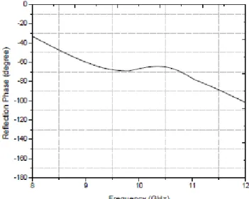
Fig. 2 illustrates the reflection coefficient phase and magnitude which can be calculated by
transmission line theory. A positive phase gradient around 10 GHz is observed for the proposed EBG
structure due to the dual layer configuration shown in Fig.1. Most of the conventional EBG structure
have negative phase gradient which exhibits relatively small bandwidth. The reflection magnitudes
shown in Fig. 3 have a minimum value of 0.55 at 9.55 GHz. The detail analysis of the same type of
EBG superstrate is done in [25] using transmission line model. The structure is modeled using
equivalent cascade transmission line network and analyzed using smith chart.
Fig. 3. Plot of the magnitude of the reflection coefficient
III. FEED ANTENNA
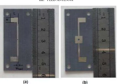
Fig. 4. The fabricated model (a) Top view of fabricated dipole with dimensions (b) Bottom view of
the fabricated dipole
the design of EBG resonator antenna. Different type of antennas are used as a feed antenna for the
EBG resonator antennas such as waveguide aperture in the ground plane [19], probe-fed patch
antenna [20], monopole antenna [21], slot coupled patch antenna [22].
Fig. 5. Fabricated assembled feed dipole antenna
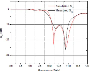
Fig. 6. The plot of the simulated and measured scattering parameter S11 for the feed dipole antenna
In this work a double side patch dipole antenna fabricated on both side low loss substrate as shown
in the Fig. 4. Fig. 4 (a) shows the top view and one pole of each dipole can be seen. The other pole of
each dipole element is etched on the bottom of the dielectric substrate as shown in Fig. 4 (b). The
antenna is design on a low loss dielectric substrate with a thickness of 0.8mm and having dielectric
constant of 2.65. The dipole patch antenna is spaced from the ground plane by 2.5mm air gap with
Teflon spacers at all corners of the substrate. These dielectric spacers are also included in the design
of antenna in the CST. The air gap drastically reduces the surface wave and thus gives us good
impedance matching at the desired frequency bands. The dimensions of the ground plane is 2.4λ0 x
2.4λ0 at 10 GHz. The dimension of the antenna and their feed are L = 6.85 mm, W = 4.6 mm, and Wfeed
using etching technique. The simulated S11 of the antenna is validated by the measured S11 as shown in
the Fig. 5. There is some difference in both the results which may be associated with the fabrication
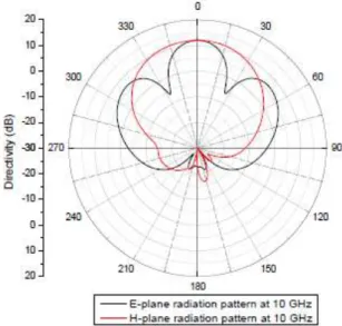
tolerances and poor performance of the SMA connector at high frequencies. The polar plot for the
radiation pattern of the antenna in the E-plane (yoz) and H-plane (xoz) at 10 GHz are shown in Fig. 6.
The fabricated feed antenna is shown in Fig. 7. This antenna is feed from the bottom which is easy to
handle in comparison to side feed antennas [22-26]. This antenna is used as a feed antenna for the
design of wide band EBG antenna discussed in the next section.
Fig. 7. The simulated radiation pattern of the feed dipole in E-plane and H-plane
IV. EBG RESONATOR ANTENNA DESIGN
The wideband EBG resonator antenna is design using the EBG superstrates and the wideband feed
dipole antenna describe in the previous sections. The EBG structure is suspended at a height h above
the aluminum ground plane with the help of pillars made of low loss dielectric materials Teflon as
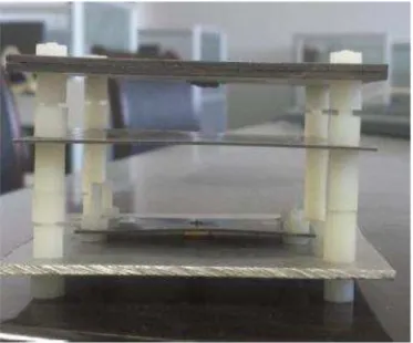
shown in Fig. 8.
Fig. 9. The fabricated prototype of the proposed EBG antenna
These Teflon spacers with diameter 2.5mm and having a dielectric constant of 2.1 is also modeled
in CST to make their electromagnetic effect also into account. The antenna is feed at the center with
the help of feed antenna describe in the previous section decreases the diffractions at the edge.
Furthermore, as the EBG structure design was based on the excitation of plane wave and all the
design parameters of the antenna cannot be varied. However, the distance between the EBG and the
ground plane h is adjustable, which is optimized to 15.5 mm to get the satisfactory results. The final
optimized dimensions of the antenna are 72mm x 72mm x 36mm. The fabricated prototype antenna is
shown in the Fig. 9.
V. RESULTS AND DISCUSSIONS
The simulation and measured reflection coefficient (S11) of the proposed EBG antenna is illustrated
in Fig. 10. The simulation results are obtain from CST 2012 using full wave analysis which are
validated with the help of measured results which are obtain with the help of an Agilent Vector
Network Analyzer (VNA) E8363B. The simulated impedance bandwidth for S11 < -10dB is equal to
2.65 GHz ranging from 8.65 GHz to 11.3 GHz. However, the measured impedance bandwidth for S11
<-10dB is equal to 2.55 GHz ranging from 8.7 GHz to 11.25 GHz. These few discrepancies may be
due to fabrication and assembling tolerances. It is also observed that the bandwidth of proposed EBG
antenna drastically increases in comparison to the feed antenna mostly towards the lower frequencies.
The gain and radiation pattern of the antenna were measured in an anechoic chamber with the help of
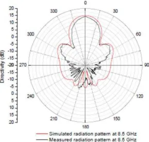
Agilent VNA E8363B and standard gain horn antennas. The simulated and measured radiation
patterns at 8.7 GHz, 10 GHz, and 11 GHz in E-plane are shown in Fig. 11, Fig. 12, Fig. 13
respectively. The simulated and measured radiation patterns are shown in Fig. 14, Fig. 15, Fig. 16
Fig. 10. The plot of simulated and measured reflection spectra of the proposed EBG resonator
antenna
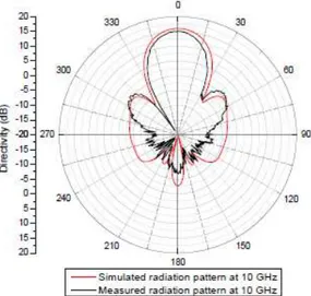
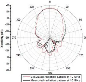
The simulated radiation pattern obtained from the CST is validated by the measured results in
general, particularly in the boresight. The measured gain is slightly lesser from simulated one due to
the fabrications and measuring tolerances. The sidelobes levels are more different in simulation and
measured results. This may be due to the radiation of the cable, SMA connector and fabrication
tolerances. The gain versus frequency plot is plotted in the Fig. 17, which depicts a 3dB bandwidth of
about 2.5 GHz ranging from 8.5 GHz to 11 GHz. As compared to the results given in [22], the gain of
the antenna is higher by about 3 dB.
Fig. 12. Polar plot of the simulated and measured radiation pattern in E-plane at 10 GHz
Fig. 13. Polar plot of the simulated and measured radiation pattern in E-plane at 11 GHz
Fig. 15. Polar plot of the simulated and measured radiation pattern in H-plane at 10 GHz
Fig. 16. Polar plot of the simulated and measured radiation pattern in H-plane at 11 GHz
VI. CONCLUSIONS
The EBG resonator antenna with high gain and large bandwidth feed by a double sided dipole patch
antenna was proposed. An EBG superstrate composed of double layer dielectric sheets of same
materials with different thickness which exhibit positive reflection phase gradient at the desired
operating frequency band. This positive phase gradient contributes to the widening of bandwidth. A
prototype EBG resonator antenna was design and fabricated at X-band. The simulation results
obtained from CST microwave 2012 were compared with measured results obtain with the help of
VNA and anechoic chamber system and were found matching at the desire frequency band. The
proposed design can be extended to different frequencies by properly adjusting the dimensions of the
EBG antenna.
REFERENCES
[1] Zeb, B. A., Y. Ge, K. P. Esselle, Z. Sun, and M. E. Tobar, A simple dual band electromagnetic band gap resonator antenna based on inverted reflection phase gradient, IEEE Transactions on Antennas and Propagation, Vol. 60, No. 10, 4522-4529, Oct. 2012.
[2] B.A. Zeb, K.P. Esselle and R.M. Hashmi Computational Models for Bandwidth Enhancement of Electromagnetic Bandgap (EBG) Resonator Antennas and their Limitations 2015 IEEE International Conference on Computational Electromagnetics, p 19-21, March 2, 2015.
[3] Y. J. Lee, J. Yeo, R. Mittra, and S. P. Wee, Application of electromagnetic bandgap (EBG) superstrates with controllable defects for a class of patch antennas as spatial angular filters, IEEE Trans. Antennas Propag., vol. 53, no. 1, pp. 224-235, Jan. 2005.
[4] A. R. Vaidya, R. K. Gupta, S. K.Mishra, and J.Mukherjee, High-gain low side lobe level Fabry Perot cavity antenna with feed patch array, Progr. Electromagn. Res., vol. 28, pp. 223-238, 2012.
[5] J. R. Kelly, T. Kokkinos, and A. P. Feresidis, Analysis and design of sub wavelength resonant cavity type 2-D leaky-wave antennas, IEEE Trans. Antennas Propag., vol. 56, no. 9, pp. 2817-2825, Sep. 2008.
[6] Y. Lee, X. Lu, Y. Hao, S. Yang, J. Evans, and C. G. Parini, Low-profile directive millimeter-wave antennas using free-formed three-dimensional (3-D) electromagnetic bandgap structures, IEEE Trans. Antennas Propag. vol. 57, no. 10, pp. 2893-2903, Oct. 2009.
[7] R. M. Hashmi, B. A. Zeb, and K. P. Esselle, Wideband High-Gain EBG Resonator Antennas With Small Footprints and All-Dielectric Superstructures, IEEE Transactions on Antennas and Propagation, vol. 62, pp. 2970-2977, 2014.
[8] K. Konstantinidis, A. Feresidis, and P. S. Hall, Multi-layer Partially Reflective Surfaces for Broadband Fabry-Perot Cavity Antennas, IEEE Transactions on Antennas and Propagation, 2014.
[9] H. Vettikalladi, O. Lafond, and M. Himdi, High-efficient and high gain superstrate antenna for 60-GHz indoor communication, IEEE Antennas Wireless Propag. Lett., vol. 8, pp. 1422-1425, 2009.
[10] Z. H. Wu and W. X. Zhang, Broadband printed compound air-fed array antennas, IEEE Antennas Wireless Propag. Lett., vol. 9, pp. 187-190, 2010.
[11] Moustafa, L. and B. Jecko, EBG structure with wide defect band for broadband cavity antenna applications, IEEE Antennas and Wireless Propagation Letters, Vol. 7, 693-696, 2008.
[12] Leger, L., C. Serier, R. Chantalat, M. Thevenot, T. Monediere, and B.Jecko, 1D dielectric electromagnetic band gap (EBG) resonator antenna design, Annales des Telecommunications, Vol. 59, No. 34, 242-260, Mar.Apr. 2004.
[13] Costa, F. and A. Monorchio, Design of subwavelength tunable and steerable Fabry-Perot or leaky wave antennas, Progress In Electromagnetics Research, Vol. 111, 467-481, 2011.
[14] Pirhadi, A., F. Keshmiri, M. Hakkak, and M. Tayarani, Analysis and design of dual band high directive EBG resonator antenna using square loop FSS as superstrate layer, Progress In Electromagnetics Research, Vol. 70, 1-20, 2007. [15] Feresidis, A. P., G. Goussetis, S. Wang, and J. C. Vardaxoglou, Artificial magnetic conductor surfaces and their
application to low-profile highgain planar antennas, IEEE Transactions on Antennas and Propagation, Vol. 53, No. 1, 209-215, Jan. 2005.
[16] Rodes, E., M. Diblanc, E. Arnaud, T. Monediere, and B. Jecko, Dual band EBG resonator antenna using a single-layer FSS, IEEE Antennas and Wireless Propagation Letters, Vol. 6, 368- 371, 2007.
[17] Leger, L., T. Monediere, and B. Jecko, Enhancement of gain and radiation bandwidth for a planar 1-D EBG antenna, IEEE Microwave and Wireless Components Letters, Vol. 15, No. 9, 573- 575, Sep. 2005.
[18] Moustafa, L. and B. Jecko, Design of a wideband highly directive EBG antenna using double-layer frequency selective surfaces and multifeed technique for application in the Ku-band, IEEE Antennas and Wireless Propagation Letters, Vol. 9, 342-346, 2010.
[19] Feresidis, A. P. and J. C. Vardaxoglou, High gain planar antenna using optimized partially reflective surfaces, IEE Proceedings on Microwaves, Antennas and Propagation, Vol. 148, No. 6, 345-350, Dec. 2001.
[20] Moustafa, L. and B. Jecko, Design and realization of a wide- band EBG antenna based on FSS and operating in the Ku-band, International Journal of Antennas and Propagation, Vol. 2010, 8 pages, Article ID 139069, 2010.
[22] Naizhi W, Qiang Liu, Changying Wu, Larbi Talbi, Qingsheng Zeng, and Jiadong Xu, Wideband Fabry-Perot Resonator Antenna with two Complementary FSS Layers, IEEE Transactions on Antennas and Propagation, Vol. 62, No. 5, 2463-2471, May. 2014.
[23] N. Wang, L. Talbi, Q. Zeng and J. Xu, Wideband High Gain 1-D EBG Resonator Antenna, IEEE International Wireless Symposium, IWS 2013.
[24] N. Wang, J. Xu, and Q. Zeng Broadband EBG resonator antenna using a combination of different dielectric substrates, IEEE Antennas and Propagation Society International Symposium, APSURSI 2013.
[25] N. Wang, C. Zhang, Q. Zeng, N. Wang, and Jiadong Xu New Dielectric 1-D EBG Structure for the Design of Wideband Resonator Antennas, Progress In Electromagnetics Research, Vol. 141, 233-248, 2013.
[26] N. Wang, L. Talbi, Q. Zeng and J. Xu, Impacts of Surface Waves on performance of an EBG Resonator Antenna, IEEE International Wireless Symposium, IWS 2013.
[27] Feresidis, A. P. and J. C. Vardaxoglou, A broadband high gain resonant cavity antenna with single feed, First European Conference on Antennas and Propagation, EuCAP 2006, 1-5, Nov. 2006.
[28] E. Rodes, M. Diblanc, E. Arnaud, T. Monediere, and B. Jecko, Dualband EBG resonator antenna using a single-layer FSS, IEEE Antennas Wireless Propag. Lett., vol. 6, pp. 368371, 2007.