Aline S. de Paula
[email protected] Universidade de Brasília Department of Mechanical Engineering 70910-900 Brasília, DF, Brazil
Marcelo A. Savi
[email protected] Universidade Federal do Rio de Janeiro COPPE – Department of Mechanical Engineering P.O. Box 68.503 21941-972 Rio de Janeiro, RJ, Brazil
Dimitris C. Lagoudas
[email protected] Texas A&M University Department of Aerospace Engineering 3141 TAMU – CS 77843 Texas, USA
Nonlinear Dynamics of a SMA
Large-Scale Space Structure
Large-scale structures are of special interest of aerospace applications, especially the ones involving smart materials. This paper deals with an archetypal system with two degrees of freedom that resembles the use of SMA elements as vibration isolation systems on a sparse aperture satellite array. The system has SMA elements in two perpendicular directions connected to a mass. Each SMA element is connected to a base structure. Imperfections are represented by establishing a comparison between two different systems: ideal and perturbed configuration system. The perturbed configuration is characterized by a situation where all SMA elements are in a stress-free state. The thermomechanical behavior of SMA elements is described by a constitutive model with internal constrains. Numerical tests of this system are of concern showing its general dynamical behavior. Periodic and chaotic motions are investigated showing the complex behaviors of this kind of system. The effect of imperfection in system dynamics is also discussed.
Keywords: shape memory alloys, smart structures, aerospace structures, nonlinear dynamics
Introduction
The unique thermomecanical characteristics of shape memory alloys (SMAs) are motivating the conception of several applications related to aerospace, biomedicine, and robotics. General overviews about SMAs application can be found in different references, as for instance: Lagoudas (2008); Paiva and Savi (2006); Machado and Savi (2003); Denoyer et al. (2000); Webb et al. (2000); Van Humbeeck (1999).
Dynamical applications of systems built with SMA elements explore the high dissipation capacity related to the hysteretic behavior and the property changes due to temperature variations. Several research efforts presented different aspects of SMA applications in dynamical systems that include vibration absorbers and composite structures (Williams et al., 2005; Rustighi et al., 2005; Elahinia et al., 2005; Nae et al., 2004; Birman, 2008; Tiseo et al., 2010; Savi et al., 2011).
The dynamical response of SMA systems presents a very rich and complex behavior. Periodic, quasi-periodic and chaotic responses are usually presented for dynamical system with SMA elements. There are several research efforts dealing with this kind of system. Bernardini and Rega (2011a,b) presented a general overview of SMA dynamical response.
Savi and Braga (1993) treated the dynamical response of SMA systems showing periodic and chaotic behaviors. Machado et al. (2004) discussed bifurcation and crises in a SMA oscillator. Both articles treated one-degree of freedom oscillators (1DOF) employing a polynomial constitutive model to describe the thermomechanical behavior of SMAs. Lacarbonara et al. (2004) investigated the nonlinear response of a 1DOF SMA oscillator numerically demonstrating that a rich class of solutions, including discontinuity of frequency responses, quasi-periodicity and chaos could arise in nearly adiabatic conditions. Bernardini and Rega (2005) investigated a 1DOF system by considering a different thermomechanical model presenting the same richness for SMA oscillators. Aspects as nonlinear resonant conditions and thermomechanical coupling influence were treated. Savi et al. (2008) discussed the SMA response by considering a constitutive model that matches experimental data for quasi-static analysis. Investigations included tension-compression asymmetry and showed
interesting results as multistability and chaos. Machado et al. (2009) proposed a procedure to evaluate Lyapunov exponents in hysteretic systems, presenting SMA as an application of the general procedure. Once again, a rich response is related to the SMA system. Recently, SMA oscillators with constraints have been investigated considering a discontinuous support that can be employed for vibration reduction. Sitnikova et al. (2010) and Santos and Savi (2009) explored this idea using different constitutive models for the thermomechanical description of SMAs, establishing comparisons with the dynamical response of an oscillator with elastic support.
The dynamical behavior of SMA systems with multi-degrees of freedom seems to be much more complex. Savi and Pacheco (2002) presented an investigation considering one- and two-degree of freedom systems. Machado et al. (2003) revisited the 2DOF system showing different aspects of bifurcation and chaos. Large-scale structures might contain hundreds of connected nodes, being related to multi-degree of freedom systems. This kind of structure is of special interest for aerospace applications including antennas. Therefore, aerospace industry demands for a general comprehension of dynamical behavior of multi-degree of freedom SMA systems.
A typical large-scale structure with embedded SMA actuators is shown in Fig. 1, representing a two-dimensional lattice connected by SMA elements. An archetypal model of this large-scale structure is also represented in Fig. 1, being composed of a single mass connected by SMA elements.
Figure 1. SMA lattice.
Machado (2007) investigated the use of shape memory alloys for vibration isolation and damping of mechanical systems. Specifically, it is treated a device composed of a mass connected to a frame through two SMA wires subjected to a series of continuous acceleration functions in the form of a sine sweep. This system is a one-dimensional version of the one treated in this work. Numerical and experimental investigations were performed analyzing frequency responses and transmissibility of the device as well as temperature variations of the SMA wires.
This article deals with the dynamical response of a 2D-SMA grid. Adaptive aerospace structures with shape memory alloy actuators are examples of dynamical systems that may behave as the structure considered in this paper. An iterative numerical procedure based on the operator split technique (Ortiz et al., 1983), the orthogonal projection algorithm (Savi et al., 2002b) and the classical fourth order Runge-Kutta method is developed to deal with nonlinearities in the formulation. Numerical investigation is carried out considering free and forced responses of the pseudoelastic structure showing a number of interesting, complex behaviors. The influence of imperfections is of concern and chaotic behavior is of special interest.
Mathematical Model
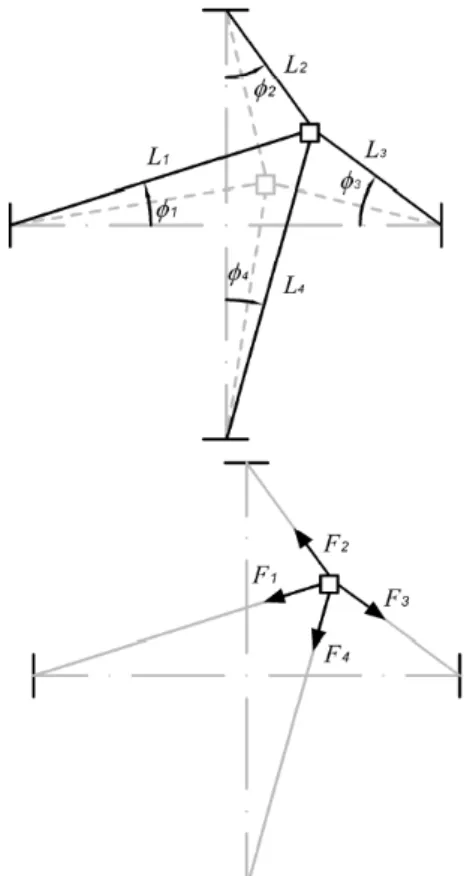
The SMA lattice archetypal model is composed of SMA elements in two perpendicular directions linked by a mass. Each SMA element is connected to a base structure, as shown in the schematic picture of Fig. 2, which shows the SMA lattice at the ideal configuration, where all SMA elements have the same length,
L0. Besides this ideal situation, it is important to describe a non-ideal situation where a perturbed configuration may represent some geometrical imperfection, for example. The perturbed configuration represents a situation with perturbations from the ideal configuration in which all SMA elements are in a stress-free state. Figure 3 presents the perturbed configuration and the deformed configuration. Figure 3 also presents the system of coordinates and the restitution forces acting in the mass.
X Y
m
3 2
1
4
Figure 2. Schematic picture of the SMA lattice.
Figure 3a. Different configurations of the SMA lattice (geometrical aspects).
SMA Actuators
Figure 3b. Different configurations of the SMA lattice (coordinates and forces).
The SMA grid stress-free state is defined by bar-variables:
4 3 2 1, , , ,
,yϕ ϕ ϕ ϕ
x . This state defines the length of each SMA
actuator, l1,l2,l3,l4, and the origin of the coordinate system (x, y). With the help of geometric considerations, it is possible to write:
x x X= +
y y Y= +
i i
i ϕ ϕ
φ = + (i = 1,2,3,4) (1)
The length of each bar is given by:
2 2
1 1
1 (lcos x) (y y)
L = ϕ + + + , l1= (l1cosϕ1)2+y2
2 2
2 2
2 (lcos y) (x x)
L = ϕ − + + , l2= (l2cosϕ2)2+x2
2 2
3 3
3 (lcos x) (y y)
L = ϕ − + + , l3= (l3cosϕ3)2+y2
2 2
4 4
4 (l cos y) (x x)
L = ϕ + + + , l4= (l4cosϕ4)2+x2
(2)
These lengths can be used to evaluate the deformation of each bar as follows:
i i i i l l L − =
ε (i = 1,2,3,4) (3)
The angles that define the SMA actuator position are described as follows: (4) 1 1 1 1 cos cos L x l + = ϕ
φ ,
1 1 sin L y y+ = φ 2 2 2 2 cos cos L y l − = ϕ
φ ,
2 2 sin L x x+ = φ 3 3 3 3 cos cos L x l − = ϕ
φ ,
3 3 sin L y y+ = φ 4 4 4 4 cos cos L y l + = ϕ
φ ,
4 4 sin L x x+ =
φ (4)
It is assumed that the mass m is excited by an external force characterized by a sinusoidal excitation with amplitude Fx and Fy in direction x and y, respectively, and frequency ωx and ωy in the same directions. Moreover, although the gravity can vary significantly in aerospace applications, it is assumed a gravitational force in the y direction in terms of Earth patterns. Besides, it is assumed that all dissipations different from hysteretic behavior are due to a viscous damping, described by the coefficient c. The balance of momentum is expressed through the following equations of motion:
) sin(
sin cos
sin
cos 1 2 2 3 3 4 4
1 t F F F F F x c x m x x ω φ φ φ φ = = + + − + + & & & (5) ) sin( cos sin cos
sin 1 2 2 3 3 4 4
1 t F mg F F F F y c y m y y ω φ φ φ φ + − = = + − + + + & & & (6)
where Fi (i = 1,2,3,4) is the force on actuator i. The thermomechanical description of this force may be done by a proper constitutive model described in the next subsection.
Constitutive model
The description of each SMA actuator force Fi is related to the SMA thermomechanical behavior and it is assumed that phase transformations are homogeneous through the element. There are different ways to describe the SMA behavior, see e.g. Lagoudas (2008) and Paiva and Savi (2006) for an overview of constitutive models. Here, a constitutive model with internal variables previously discussed in different references (Savi et al., 2002b; Baêta-Neves et al., 2004; Paiva et al., 2005; Savi and Paiva, 2005; Monteiro et al., 2009; Aguiar et al., 2010; Oliveira et al., 2010) is employed.
In order to present the constitutive equations, let us consider strain (ε), temperature (T), and three more state variables associated with the volume fraction of each phase: is associated with tensile detwinned martensite, − is related to compressive detwinned martensite, represents austenite. Actually, it is considered a fourth phase related to twinned martensite, that can be obtained from phase coexistence condition (βM = 1 – β+ + β− + βA). With these assumptions, it is possible to obtain a complete set of constitutive equations that describes the thermomechanical behavior of SMAs as follows:
(
0)
) ](
[ E T T
E + + h − − −
= ε α α β− β+ Ω
σ (7)
(
)
[
]
π χ(
)
[
]
π χh h h M J J T T E E − − + − − − ∂ + ∂ − − − − + − + − + − = 0 2 ) ]( ) ( 2 [ 1 Ω ε α β β α α α Λ αε η β& (9)
(
)
[
]
(
A M)
(
)
[
h]
A π A χA h M A A A J J T T E E ∂ + ∂ − − + − − + + + − + − − = + − + − ) ( ) ( 2 1 1 0 2 β β α ε Ω Ω Λ β β α ε η β & (10)
where E=EM+βA
(
EA−EM)
is the elastic modulus while(
A M)
A
M β Ω Ω
Ω
Ω= + − is related to the thermal expansion coefficient. Note that subscript “A” refers to austenitic phase, while
“M” refers to martensite. Moreover, parametersΛM =ΛM(T) and )
(T
A
A Λ
Λ = are associated with phase transformations stress levels. Parameter αh is introduced in order to define the horizontal width of the stress-strain hysteresis loop, while α controls the vertical hysteresis size on stress-strain diagrams.
The terms ∂nJπ (n = +, −, A) are sub-differentials of the indicator function Jπ with respect to (Rockafellar, 1970). The
indicator function Jπ=Jπ
(
β+,β−,βA)
is related to a convex setπ, which provides the internal constraints related to the phases’ coexistence. With respect to evolution equations of volume fractions, η+, η− and ηA represent the internal dissipation related to phase transformations. Moreover ∂nJχ (n = +, −, A) are
sub-differentials of the indicator function J with respect to χ β&n (n = +,
−, A) (Rockafellar, 1970). This indicator function is associated with the convex set χ, which establishes conditions for the correct description of internal subloops due to incomplete phase transformations.
Concerning the parameters definition, temperature dependent relations are adopted for ΛM and ΛA as follows:
≤ − > − + − = M M M M M M M M T T T T T T T if if ) ( 0 1 0 Λ Λ Λ Λ (11) ≤ − > − + − = M A M M M A A A T T T T T T T if if ) ( 0 1 0 Λ Λ Λ Λ (12)
Here, TM is the temperature below which the martensitic phase
becomes stable in a stress-free state. Besides, ΛM0 , Λ1M, Λ0A and
A 1
Λ are parameters related to critical stress for phase transformation.
In order to contemplate different characteristics of the kinetics of phase transformation for loading and unloading processes, it is possible to consider different values to the internal dissipation
parameter ηn (n = +, − , A): ηLn and ηUn during loading and
unloading process, respectively. For more details about the constitutive model, see Paiva et al. (2005) and Savi and Paiva (2005).
Equations of Motion
Based on the constitutive modeling, it is possible to calculate the force in each SMA actuator as follows:
(
0)
) ](
[ E T T
L A E
F i i i ih i i i i
i i i
i= ε + α + α β−−β+ −Ω −
(13)
where volume fractions β+ and β− are calculated from the evolution equations presented in the previous section and i = 1,2,3,4. By defining the dimensionless variables:
t T T L Y Y L y y L X X L x x R 0 0 0 0 0 ; ; ˆ ; ˆ ; ˆ ;
ˆ= = = = θ= τ=ω
(14)
where L0 is a reference length defined in the ideal configuration (x=y=0; ϕ1=ϕ2=ϕ3=ϕ4=0) as shown in Fig. 2. Dimensionless equations of motion are given by:
) sin( sin cos sin cos ˆ
ˆ 1 1 2 2 3 3 4 4
τ ϖ δ φ Γ φ Γ φ Γ φ Γ ξ x x x x = = + + − + ′ + ′′ (15) ) sin( cos sin cos sin ˆ
ˆ 1 1 2 2 3 3 4 4
τ ϖ δ φ Γ φ Γ φ Γ φ Γ ξ y y RA E mg y y + − = = + − + + ′ + ′′ (16)
(
)
). 4 , 3 , 2 , 1 ( ) ]( ˆ ˆ [ 0 = − − − + + = − + i i i i i h i E i i i E ii µ ε α µ α β β µ θ θ
Γ Ω (17) where 0 2 0 mL A ER = ω ; 0 ω ξ m c = ; R E mL A α ω α
α= 2 =
0 0 ˆ ; h R h h mL A E α ω α
α = 2 =
0 0 ˆ ; A E F mL F R x x
x= 2 =
0 0ω δ ; A E F mL F R y y
y= 2 =
0 0ω δ ; R R R R R E T mL AT Ω ω Ω
Ω= 2 =
0 0 ˆ ; R E E E = µ ; R Ω Ω µΩ = ;
0 ω
ω
ϖ = . (18)
From now on, , , and will be respectively replaced by x,
X, y and Y.
Numerical Simulations
L0 = 2.236 m at ideal configuration and a cross section area of A = 0.25 m2. Therefore, the parameters defined in Eqs. (15)-(18) assume the values of ω02=6×10⁹, θ=1.28, αˆ=2.78×10⁻³,
4
10 17 . 9
ˆ = × −
Ω .
Table 1. SMA constitutive parameters.
EA (GPa)
EM (GPa)
α
(MPa) α
h ΛM0
(MPa)
54 54 150 0.052 0.15
M
1
Λ
(MPa)
A
0
Λ
(MPa)
A
1
Λ
(MPa)
ΩA (MPa/K)
ΩM (MPa/K)
41.5 0.63 185 0.74 0.17
TM (K)
TA (K)
ηL (MPa.s)
291.4 307.7 10
Simulations are performed considering two different situations: an ideal configuration where ̅ = = 0; and a perturbed configuration where ̅ = = 0.1. Free and forced vibrations are treated. Concerning forced vibrations, only vertical excitation is treated, and therefore, δx = 0.
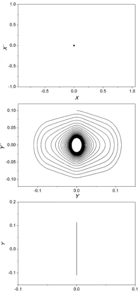
Figure 4. Free response of the ideal configuration: state space projections.
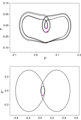
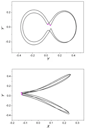
Figure 5. Free response of the perturbed configuration: state space projections.
Free Vibrations
Let us start with the free vibration analysis. Initially, it is assumed the ideal configuration where ̅ = = 0. Therefore, it is expected that an initial condition related to Y-direction is
associated with a movement restricted to the Y-direction. In order
to observe this behavior, let us consider a velocity in the
Y-direction as initial condition. Results from simulations are presented in Fig. 4, which presents three subspaces of the phase space related to the free-response of the structure. We called
X-space built with (X, X´); Y-space built with (Y, Y´); and XY-space
built with (X, Y). Note that in the Y-space, hysteretic behavior
dissipates energy until elastic response is reached in the steady-state. The X-space is stationary. The XY-space clearly shows that
the movement is restricted to the Y-direction.
A perturbed configuration is now treated by assuming that ̅ = = 0.1. The same initial conditions of the previous simulation are considered, which means that we are imposing a velocity in the
Y-direction as initial conditions. Results from simulations are presented in Fig. 5, which presents three subspaces of the phase space related to the free-response of the structure: (X, X´); (Y, Y´);
and (X, Y). Note that in the Y-space, hysteretic behavior dissipates
energy until elastic response is reached in the steady-state. The
this condition, the system presents a movement that is not restricted in the Y-direction, presenting a movement in the
X-direction as well. This behavior can be understood by observing the thermo-mechanical behavior of each SMA element. Figure 6 presents volume fraction evolution of each phase at each actuator while Fig. 7 presents the stress-strain curves of each SMA actuator. It is noticeable that phase transformations only occur in elements 2 and 4, both related to Y-direction.
Figure 6. Volume fraction evolutions of the free response.
Figure 7. Stress-strain curves of the free response.
Forced Vibrations
This section considers the forced vibration analysis of the system. Initially, let us consider the ideal configuration (x=y=0). Excitation is applied only in Y-direction and therefore, the system
dynamics is restricted to this direction. By considering an excitation with δy = 0.04 and ϖy = 0.45, the system presents a periodic
excitation parameters to δy = 0.4 and ϖy = 0.45, the system
presents a different periodic response (Fig. 8, right panel). Figure 8 presents Y-space together with the Poincaré section. The X-X´
projection is stationary in the same way of the free vibration analysis shown in Fig. 4.
Figure 8. Forced vibration of the system when undeformed configuration coincides with ideal situation (x=y=0). Left panel: δy = 0.04 and
y
ϖ = 0.45; Right panel: δy = 0.4 and ϖy = 0.45.
The perturbed configuration with x=y=0.1 is now on focus. Initially, let us consider an excitation with δy = 0.04 and ϖy = 0.45.
Under this condition, the system presents a periodic response as shown in Fig. 9. This steady-state response is related to phase transformations that preponderantly occur in vertical elements (2 and 4). It is noticeable that the perturbed configuration promotes a coupling between X-Y directions. Large transients are expected,
especially in the X-direction due to a less amount of phase
transformation. But it should be highlighted that the system presents the same periodic pattern from the one of the ideal configuration.
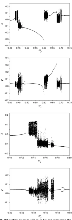
By considering a higher forcing amplitude δy = 0.4, the system response dramatically changes. In order to analyze the global behavior of this system, bifurcation diagrams are constructed by assuming a stroboscopically quasi-static increase of the frequency. Figure 10 presents the bifurcation diagram that presents the X and Y
values by increasing the forcing frequency ϖy. It is noticeable the
bifurcation scenarios that result in chaotic behaviors related to a cloud of points for some frequency values. The lower panel of Fig. 10 presents enlargements of some frequency range showing the details of the bifurcation scenarios.
Based on the global analysis obtained by the bifurcation diagrams, let us investigate different kinds of responses related to distinct values of frequency. Essentially, results are presented by
considering different projections of the phase space also indicating Poincaré section: (X, X´); (Y, Y´); and (X, Y).
Figure 11 shows a period-1 behavior when ϖy = 0.48. By
considering ϖy = 0.49 the system presents a period-2 behavior
(Fig. 12).
A frequency value of ϖy = 0.432 is related to a chaotic
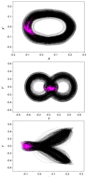
behavior (Fig. 13). Figure 14 presents details of the chaotic attractors for this response. The consideration of an external viscous damping in the system highlights the fractal structure of the attractor. Figure 15 presents the same results by increasing the system dissipation by assuming ξ = 0.05. It is important to highlight that viscous damping is considered to represent all kinds of dissipation different from the one related to the hysteretic behavior. Therefore, it is representing different dissipative aspects of the system as the media where the structure is.
Figure 10. Bifurcation diagram with δy = 0.4 and increasing the forcing frequency ϖy.
Figure 12. Period-2 behavior for δy = 0.4 and ϖy = 0.49: projections of the phase space.
Figure 13. Chaotic behavior for δy = 0.4 and ϖy = 0.432: projections of the phase space.
Figure 15. Chaotic behavior for δy = 0.4 and ϖy = 0.45: projections of the phase space.
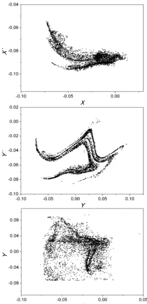
Figure 16 presents the chaotic attractors that show a different chaotic pattern. Once again, the increase in system dissipation by assuming ξ = 0.05 highlights the fractal structure of the attractor as shown in Fig. 17.
Conclusions
This article deals with the dynamical response of a 2D-SMA grid that represents adaptive structures with shape memory alloy actuators. This archetypal system has SMA elements in two perpendicular directions connected to a mass and each SMA element is connected to a base structure. Imperfections are represented by a perturbed configuration where all SMA elements are in a stress-free state. Therefore, two different systems are of concern: ideal and perturbed configuration system. The thermomechanical behavior of SMA elements is described by a constitutive model with internal constrains. An iterative numerical procedure based on the operator split technique, the orthogonal projection algorithm and the classical fourth order Runge-Kutta method is developed to deal with nonlinearities in the formulation. Numerical investigation is carried out considering free and forced responses of the pseudoelastic structure showing a number of
interesting, complex behaviors. It is important to highlight the comparison between ideal and perturbed configuration systems that shows how imperfections can alter system characteristics providing a coupling between both directions. Chaotic responses are discussed showing different patterns of this kind of response. In general, the increase of geometrical imperfections tends to increase the complexity of the system response. Therefore, the system has greater possibility to present chaotic motion. These results show the importance of proper description of geometrical imperfections in nonlinear analysis. The qualitative different patterns related to ideal and perturbed configuration systems is an important aspect that should be considered in system dynamics. The design of aerospace structures should consider this kind of possibility in order to avoid unexpected undesirable behaviors.
Acknowledgements
The authors would like to acknowledge the support of the Brazilian Research Agencies CNPq, CAPES, and FAPERJ and through the INCT-EIE (National Institute of Science and Technology - Smart Structures in Engineering) the CNPq, FAPEMIG and the Air Force Office of Scientific Research (AFOSR).
Figure 17. Chaotic attactors for δy = 0.4, ϖy = 0.45 and ξ = 0.05.
References
Aguiar, R.A.A., Savi, M.A. and Pacheco, P.M.C.L., 2010, “Experimental and numerical investigations of shape memory alloy helical springs”, Smart Materials and Structures, Vol. 19, No. 2, Article 025008, pp.1-9.
Baêta-Neves, A.P., Savi, M.A. and Pacheco, P.M.C.L., 2004, “On the Fremond’s constitutive model for shape memory alloys”, Mechanics Research Communications, Vol. 31, No. 6, pp. 677-688.
Bazant, Z.P. and Cedolin, L., 1991, “Stability of structures”, Oxford Press. Bernardini, D. and Rega, G., 2011a, “Chaos robustness and strength in thermomechanical shape memory oscillators. Part I: a predictive theoretical framework for the pseudoelastic behaviorPart II: numerical and theoretical evaluation”, International Journal of Bifurcation and Chaos, Vol. 21, No. 10, pp. 2769-2782.
Bernardini, D. and Rega, G., 2011b, “Chaos robustness and strength in thermomechanical shape memory oscillators. Part II: numerical and theoretical evaluation”, International Journal of Bifurcation and Chaos, Vol. 21, No. 10, pp. 2783-2800.
Bernardini, D. and Rega, G., 2005, “Thermomechanical modelling, nonlinear dynamics and chaos in shape memory oscillators”, Mathematical and Computer Modelling of Dynamical Systems, Vol. 11, No. 3, pp. 291-314.
Birman, V., 2008, “Shape memory elastic foundation and supports for passive vibration control of composite plates”, International Journal of Solids and Structures, Vol. 45, pp. 320-335
Denoyer, K.K., Scott Erwin, R., Rory Ninneman, R., 2000, “Advanced smart structures flight experiments for precision spacecraft”, Acta Astronautica, Vol. 47, pp. 389-397.
Elahinia, M.H., Koo, J.H. and Tan, H., 2005, “Improving robustness of tuned vibration absorbers using shape memory alloys”, Shock and Vibration, Vol. 12, No. 5, pp. 349-361.
Lacarbonara, W. and Vestroni, F., 2003, “Nonclassical responses of oscillators with hysteresis”, Nonlinear Dynamics, Vol. 32, pp. 235-258.
Lacarbonara, W., Bernardini, D. and Vestroni, F., 2004, “Nonlinear thermomechanical oscillations of shape-memory devices”, International Journal of Solids and Structures, Vol. 41, No. 5-6, pp. 1209-1234.
Lagoudas, D.C., 2008, “Shape Memory Alloys: Modeling and Engineering Applications”, Springer.
Machado, L.G., 2007, “Shape Memory Alloys for Vibration Isolation and Damping”, Ph.D. Dissertation, Texas A&M University, Department of Aerospace Engineering.
Machado, L.G. and Savi, M.A., 2003, “Medical applications of shape memory alloys”, Brazilian Journal of Medical and Biological Research, Vol. 36, No. 6, pp. 683-691.
Machado, L.G., Savi, M.A. and Pacheco, P.M.C.L., 2003, “Nonlinear dynamics and chaos in coupled shape memory oscillators”, International Journal of Solids and Structures, Vol. 40, No. 19, pp. 5139-5156.
Machado, L.G., Savi, M.A. and Pacheco, P.M.C.L., 2004, “Bifurcations and crises in a shape memory oscillator”, Shock and Vibration, Vol. 11, No. 2, pp. 67-80.
Machado, L.G., Lagoudas, D.C. and Savi, M.A., 2009, “Lyapunov exponents estimation for hysteretic systems”, International Journal of Solids and Structures, Vol. 46, No. 6, pp. 1269-1598.
Nae, F.A., Ikeda T. and Matsuzaki Y., 2004, “The active tuning of a shape memory alloy pseudoelastic property”, Smart Materials and Structures, Vol. 13, pp. 503-511.
Rustighi, E., Brennan, M.J. and Mace, B.R., 2005, “A shape memory alloy adaptive tuned vibration absorber: design and implementation”, Smart Materials and Structures, Vol. 14, pp. 19-28.
Monteiro Jr., P.C.C., Savi, M.A., Netto, T.A. and Pacheco, P.M.C.L., 2009, “A phenomenological description of the thermomechanical coupling and the rate-dependent behavior of shape memory alloys”, Journal of Intelligent Material Systems and Structures, Vol. 20, No. 14, pp .1675-1687.
Oliveira, S.A., Savi, M.A. and Kalamkarov, A.L., 2010, “A three-dimensional constitutive model for shape memory alloys”, Archive of Applied Mechanics, Vol. 80, No. 10, pp. 1163-1175.
Ortiz, M., Pinsky, P.M. and Taylor, R.L., 1983, “Operator split methods for the numerical solution of the elastoplastic dynamic problem”, Computer Methods of Applied Mechanics and Engineering, 39, pp. 137-157.
Paiva, A., Savi, M.A., Braga, A.M.B. and Pacheco, P.M.C.L., 2005, “A constitutive model for shape memory alloys considering tensile-compressive asymmetry and plasticity”, International Journal of Solids and Structures, Vol. 42, No. 11-12, pp. 3439-3457.
Paiva, A. and Savi, M.A., 2006, “An overview of constitutive models for shape memory alloys”, Mathematical Problems in Engineering, Vol. 2006, Article ID56876, pp. 1-30.
Santos, B.C. and Savi, M.A., 2009, “Nonlinear dynamics of a nonsmooth shape memory alloy oscillator”, Chaos, Solitons and Fractals, Vol. 40, No. 1, pp. 197-209.
Savi, M.A. and Braga, A.M.B., 1993, “Chaotic vibrations of an oscillator with shape memory”, Journal of the Brazilian Society of Mechanical Sciences and Engineering, Vol. XV, No. 1, pp. 1-20.
Savi, M.A. and Nogueira, J.B., 2010, “Nonlinear dynamics and chaos in a pseudoelastic two-bar truss”, Smart Materials & Structures, Vol. 19, No. 11, Article 1150222010, pp. 1-11.
Savi, M.A. and Pacheco, P.M.L.C., 2002, “Chaos and hyperchaos in shape memory systems”, International Journal of Bifurcation and Chaos, Vol. 12, No. 3, pp. 645-657.
Savi, M.A., Pacheco, P.M.C.L. and Braga, A.M.B., 2002a, “Chaos in a shape memory two-bar truss”, International Journal of Non-linear Mechanics, Vol. 37, No. 8, pp. 1387-1395.
Savi, M.A., Paiva, A., Baêta-Neves, A.P. and Pacheco, P.M.C.L., 2002b, “Phenomenological modeling and numerical simulation of shape memory alloys: A thermo-plastic-phase transformation coupled model”, Journal of Intelligent Material Systems and Structures, Vol. 13, No. 5, pp. 261-273.
Savi, M.A., Sa, M.A.N., Paiva, A. and Pacheco, P.M.C.L., 2006, “Tensile-compressive asymmetry influence on the shape memory alloy system dynamics”, Chaos, Solitons & Fractals, Vol. 36, No. 4, pp. 828-842.
Sitnikova, E., Pavlovskaia, E. Wiercigroch, M. and Savi, M.A., 2010, “Vibration reduction of the impact system by an SMA restraint: Numerical studies”, International Journal of Non-linear Mechanics, Vol. 45, No. 9, pp. 837-849.
Tiseo, B., Concilio, A., Amerudi, S. and Gianvito, A., 2010, “A shape memory alloy based tuneable dynamic vibration absorber for vibration tonal control”, Journal of Theoretical and Applied Mechanics, Vol. 48, pp.135-153.
Van Humbeeck, J., 1999, “Non-medical applications of shape memory alloys”, Materials Science and Engineering A, Vol. 273-275, pp. 134-148.
Webb, G., Wilson, L., Lagoudas, D.C. and Rediniotis, O., 2000, “Adaptive control of shape memory alloy actuators for underwater biomimetic applications”, AIAA Journal, Vol. 38, No. 2, pp. 325-334.