Design and Modelling of Fuzzy and Model
Predictive Controllers for STATCOM to
enhance Transient Stability of Power
System
P.S.Ponmurugavel1, S.Mohamed Ghouse2 1
SEEE, SASTRA University, Thanjavur, Tamilnadu – 613401. 2
SEEE, SASTRA University, Thanjavur, Tamilnadu – 613401. 1
ponmurugavel89@gmail.com 2
ghouseee@yahoo.co.in
Abstract- In modern power system, Static Compensator (STATCOM) is used to alleviate the transient stability problem and damping power system oscillations. In this paper different STATCOM control scheme using fuzzy logic controller (FLC) and model predictive controller (MPC) for the Single Machine Infinite Bus (SMIB) system in improving transient stability is simulated using MATLAB/ Simulink in power systems block set. PI, FLC and MPC signals are used to control and exchange the required reactive power among the STATCOM and the power grid. A load disturbance is simulated and the behavior of the system for voltage fluctuations has been studied. Simulation results using Proportional-Integral (PI) controller, Fuzzy Logic Controller (FLC) and Model Predictive Controller (MPC) have been compared. The effectiveness of the different controllers in damping oscillations and improving power system stability has been discussed.
Keyword- Static Synchronous Compensator (STATCOM), PI controller, fuzzy logic controller (FLC), Model Predictive Controller (MPC), Flexible AC Transmission System (FACTS).
I. INTRODUCTION
Flexible AC Transmission Systems (FACTS) employs power electronics device to control the real and reactive power in modern power system for the better utilization of the existing network [1]. The beginning of FACTS as an entire network control attitude was introduced in the year 1988 and its effectiveness is now widely recognized by the power system researchers and engineers [2]. As the FACTS controllers are fast operating they are mainly utilized in improving steady state and transient stabilities of a modern power system. This enhances the maximum utilization of the existing network without further expansion and operating the network close to the thermal loadable limit [3]. The conventional shunt compensators have been replaced by Static VAR compensator (SVC) for the power system voltage stability improvement [4].
They are used to damp out power swings thereby reducing the transmission loss by proper reactive power control and enhances the transient stability. Fast acting Static synchronous compensator (STATCOM) is extensively used as dynamic shunt compensator for reactive power control in the transmission network [5]. VSC based STATCOM have been developed to control power system dynamics during fault condition. It has been reported by many researches that STATCOM with modern controller can be used to develop stability of system of multi machine system and a single machine infinite bus (SMIB) system [6]. Many advanced control technologies have been proposed by the researchers for STATCOM in improving stability of power system stability.
In this work, the effect of STATCOM in a SMIB system is studied under the MATLAB –SIMULINK power system tool bar. The variations in both real and reactive power exchange with STATCOM and without STATCOM have been studied. A proportional –Integral controller have been developed and the performance of the controller with STATCOM in the SMIB system has been analyzed for a load disturbance. Then the PI controller is replace by a more robust Fuzzy logic controller (FLC) and Model Predictive controller (MPC) in MATLAB-SIMULINK environment and the efficiency of the different controllers have been studied.
II. DYNAMIC MODEL OF SMIB WITH STATCOM
a dc capacitor (UDC) is coupled with a voltage source converter (VSC). The STATCOM V-I characteristics are displayed in fig 2.
Fig1. Dynamic model of SMIB system with STATCOM
Fig2. V-I characteristics of STATCOM
Both capacitive and inductive compensation is provided by the controller and is capable of controlling the output current value over the rated maximum inductive and capacitive range in the ac system voltage.The capacitor voltage UDC is effectively controlled by monitoring difference in phase angle between the voltage source converter voltage Uc and the line voltage of AC system. If the firing angle is advanced then the dc voltage is decreased and reactive power flow into the STATCOM. On the other hand if the firing angle is delayed then increase in the dc voltage occurs and the STATCOM will supply reactive power into ac system. Hence by the control of the firing angle of the VSC the STATCOM is operated in absorbing or pumping reactive power. By controlling the reactive power the proper voltage regulation can be achieved and the system stability can be enhanced greatly [7], [8] & [9].
The equivalent circuit of STATCOM is presented in figure.3
Fig3. Equivqlent circuit model of STATCOM
The parameter Ls and Rs represents the STATCOM transformer inductance and resistance. The basic equation of the circuit in vector form is given by
ௗ ௗ௧iabc =
ோ௦ ௦ iabc +
ଵ
௦ (Eabc – Vabc) (1) The STATCOM output equation is specified by
K is the modulation index
α represents the voltage phase angle. An equation for voltage across the capacitor is given by
Cௗௗ
ௗ௧ +GUdc = mk[sin(α + θ) ID + cos (α + θ) I Q] (3) In this equation G represents the losses associated in the capacitor while the angle α and m are the control parameters of the VSC [10] & [11]. In this work IGBT based STATCOM is used for the study and the parameter m is kept constant and the angle α is the control parameter in controlling the reactive power.
III.SIMULATION OF SIMPLE POWER SYSTEM
A. A model Power System simulation without using STATCOM
To study the transient stability phenomenon a simplest power system is analyzed by the utilization of SimPower System toolbox presented in the MATLAB/Simulink software environment. Fig.1 represents single line diagram of SMIB system which comprises of a transmission line connecting an AC power source at the sending end and a receiving side connected to a RL load. This arrangement is first studied without STATCOM using a generating source with 230 kV voltage which simulates a synchronous generator of 500MVA capacity with terminal voltage 11kV, and its associated step up transformer with 500MVA, 11/230kV rating. The real power flow and reactive power flow in this configuration and the associated sending end and receiving end parameters have been observed. In Simulink Power system blocks, the reactive and active power blocks are available for measuring the power flow both at the sending end and the receiving end.
Fig4. A simple power system – Simulink diagram
The RL load value is assumed to have a real power value of 500 MW and reactive power of 100 MVAR. The length of the transmission line is assumed to be 300Km. The readings of both sending end power and receiving end power and voltage values are observed, and it is tabulated in table 1.
TABLE 1
Simple power system without STATCOM - Simulation results
Parameters Sending end side Receiving end side
Real power kW 294 MW 271 MW
Reactive power MVAR
238 MVAR 245 MVAR
Voltage kV 230 kV 210 kV
Under this loading condition, the real power at the receiving end is lesser than the real power at sending end and the reactive power at the receiving end is also lesser than the reactive power at the sending end.
B. Simple Power System simulation with STATCOM
Fig5. A model power system with STATCOM– Simulink diagram TABLE 2
A model power system using STATCOM
Parameters Sending end side Receiving end side
Real power kW 480 MW 475 MW
Reactive power MVAR 401 MVAR 404 MVAR
Voltage kV 230 kV 229 kV
C. Simple Power System simulation with STATCOM controlled by PI controller
Fig.6 represents that PI controller is controlled STATCOM device which is compensate the voltage control and reactive power at the receiving end. First to simulate the system with STATCOM is controlled by PI controller and read the response when load disturbance will occur in simulated system.
Fig6. A model power system using STATCOM controlled by conventional PI controller
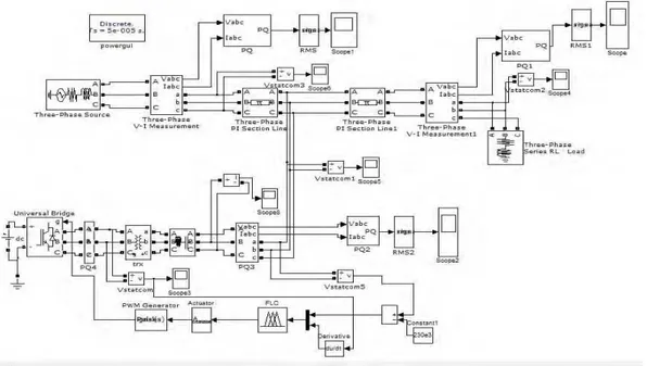
D. A model Power System simulation using STATCOM controlled by Fuzzy Logic controller (FLC)
Vpccref is compared and the error and change in error value is calculated and fed as input values to the Fuzzy Controller. Fig.7 denotes the simulation diagram of Fuzzy logic controller with STATCOM [11] [12] & [13].
Fig7. a simple power system with STATCOM controlled by Fuzzy Logic Controller– Simulink diagram
1) Mamdani method: Mamdani method is used in this work and it is computationally proficient and more
compact. The two inputs and one output method is available in two rule system. Here the inputs are X1 and X2 then output is represented as Y. In this system, error and change in error are represented as X1 and X2. The output Y is denoted as alpha.
2) Fuzzification: Five linguistic sets of fuzzy using triangular membership function is presented in fig.7a&b
and five sets of fuzzy variables used are PVB (Positive Very Big), PB (Positive Big), Z (Zero), NB (Negative Big), NVB (Negative Very Big).
Fig8 b. alpha (Y) – output membership functions
3) Defuzzification: Defuzzification is the reverse of fuzzification. Defuzzification using weighted average
method is used in this work. The Pulse duration is obtained as the defuzzified output.
4) Rule base: “If-then” format is used in forming fuzzy rules. In fuzzy rule the ‘if’ part is known as
rule-antecedent and the ‘then’ part is called rule consequent. The fuzzy controller increases the pulse duration during positive error condition and decreases the duration during negative error condition.
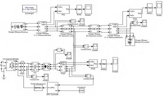
E. Simple Power System simulation with STATCOM controlled by Model Predictive controller(MPC)
Model predictive controller (MPC) concept is the most widely used of all modern advanced control technique in many control application. MPC has four important tuning parameters: the weight matrix Λ, the output weight matrix Γ, the prediction horizon P and the control horizon M. The control horizon M is the number of MV moves that MPC calculates at each sampling time to remove the current prediction error. The prediction horizon P represents the number of samples in to the future over which MPC computes the predicted process variable profile and reduces the prediction error. The weighting matrix Γ is used for scaling in the multivariable case; it permits the assignment of more or less weight for the objective of reducing the predicted error for the output variable [14].
A dynamic system model is used in order to forecast the controlled variables. The regulator variables variation to predict the response of system at each time horizon is allowed by linear vector function.
In MPC, receding horizon concept is represented as shown in fig.9
Fig9. Receding Horizon concept
From these graph, MPC can be expressed as equation, when normal model is predicted by control horizon and prediction horizon method and shows predicted output.
Fig10. A simple power system with STATCOM controlled by Model Predictive Controller– Simulink diagram
F. Discussion of Results and experimental Analysis 1. Analysis of PI controller results
a. Without load Disturbances
Fig11. Real and reactive power waveform of STATCOM with PI controller
Fig 11 shows the real power and reactive power waveform of STATCOM device with PI controller. The system settles down depending upon the gain values of PI controller. Due to the higher values of gain in PI controller, it causes peak overshoot in waveform at initial condition. This waveform is captured by using three phase active and reactive power link block in Simulink model. Here the system is settled at 0.06 sec for real and reactive power. The peak overshoot value for real and reactive power is 260 MW and 151 MVAR respectively.
b. With load Disturbances
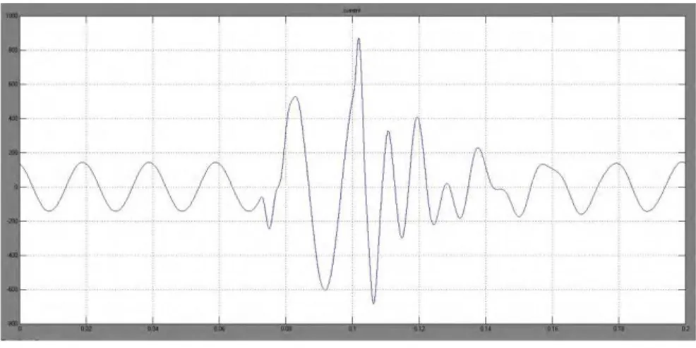
Fig13. STATCOM current waveform
Fig 12 and fig 13 represents the waveform of load voltage and STATCOM current when load disturbance is occurred. In SMIB system, two RL series load is connected as parallel in receiving end and the three phase circuit breaker is connected in between two RL load. The response of load voltage and STATCOM current is getting disturbed. Here the overshoot level of load voltage is 260 kV and response is settled at 0.12 sec, at mean time the overshoot value of STATCOM current is 870 A and settled time is 0.16sec.
2. Analysis of Fuzzy logic controller results a. Without load disturbance
Fig14. Real and reactive power waveform of STATCOM with Fuzzy Logic controller
Now the Fuzzy logic Controller replacing PI controller. Fig 14 displays the real and reactive power response of STATCOM with Fuzzy logic Controller. In that response, peak overshoot is reduced and fastest settling time when compared to PI controller output. The values of peak overshoot of Real and reactive power is 138 MW and 222 MVAR, the settling time is 0.04 sec respectively.
b. With load disturbance
Fig16. STATCOM current waveform
Fig 15 and fig 16 represents the waveform of load voltage and STATCOM current when load disturbance is occurred. Here the overshoot level of load voltage is 240 kV and response is settled at 0.10 sec, at the mean time the overshoot value of STATCOM current is 485 A and settled time is 0.14 sec respectively. When compared to PI controller response, the overshoot value of load voltage is reduced from 260 kV to 150 kV and it reaches the steady state from 0.12 sec to 0.10 sec respectively.
3. Analysis of Model Predictive Controller results a. Without load disturbance
Fig17. Real and reactive power waveform of STATCOM with Model Predictive Controller
In this case, Fuzzy logic controller is replaced by Model Predictive Controller. Fig 17 shows the real and reactive power response of STATCOM with Model Predictive Controller. In that response, peak overshoot is reduced and the settling time is faster when compared to both Fuzzy and PI controller output response. The values of peak overshoot of Real and reactive power is 125 MW and 210 MVAR, the settling time is 0.035 sec respectively.
b. With load disturbance
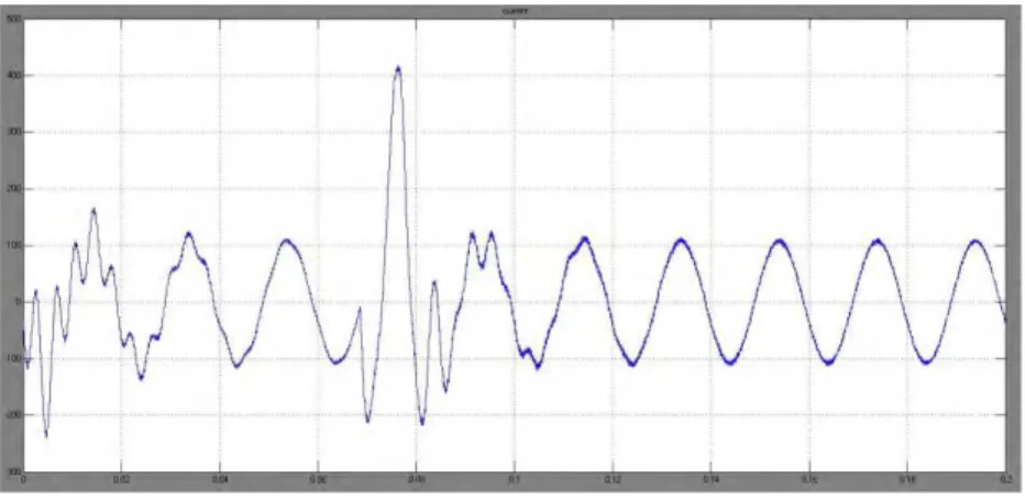
Fig19. STATCOM current waveform
Fig 18 and fig 19 represents the waveform of load voltage and STATCOM current during load disturbance when STATCOM is controlled by Model Predictive Controller. Here the overshoot level of load voltage is 232 kV and response is settled at 0.09 sec, at the mean time the overshoot value of STATCOM current is 418 A and settled time is 0.11 sec respectively. When compared to both PI controller and Fuzzy logic controller response, the overshoot value of load voltage is reduced.
Table I, table II and table III gives the comparison of PI controller, Fuzzy Logic controller and Model Predictive Controller of Peak overshoot values measured for Real & Reactive power, load current and STATCOM respectively.
TABLEI
Comparison of the Real and the Reactive power without load disturbance
No
Real Power MW and Reactive Power MVAR Controllers Peak
overshoot
Settling time sec 1 PI controller 151 MW
260 MVAR
0.06 sec
2 Fuzzy Logic
controller
138 MW 222 MVAR
0.04 sec
3 Model Predictive Controller
125 MW 210 MVAR
0.035 sec
TABLEIII
Comparison of load voltage when load disturbance occurs
No
Load voltage kV Controllers Peak
overshoot
Settling time sec 1 PI controller 260 kV 0.12 sec
2 Fuzzy Logic
controller
240 kV 0.10 sec
3 Model Predictive Controller
232 kV 0.09 sec
TABLEIIII
Comparison of STATCOM current when load disturbance occurs
No
STATCOM current A Controllers Peak
overshoot
Settling time sec 1 PI controller 870 A 0.16 sec
2 Fuzzy Logic
controller
485 A 0.14 sec
3 Model Predictive Controller
IV.CONCLUSION
In this paper the STATCOM control scheme for the Single-Machine Infinite Bus (SMIB) system to improve transient stability is simulated using MATLAB/Simulink in power systems block set. The Simulation models of PI, FLC and MPC were developed. The Performance of different controllers is analyzed for a load disturbance. When comparing the results, performance of PI controller with STATCOM, gives high peak overshoot and more settling time. Performance of fuzzy logic controller with STATCOM, gives low peak overshoot and quick settling time when comparing the results with PI controller. The Response of Model Predictive controller with STATCOM, the values of peak overshoot and settling time is found to be lower than the results of FLC with STATCOM. Thus MPC provide better control in transient stability improvement of the simulated power system.
ACKNOWLEDGMENT
The authors of this work greatly indebted to Prof.R. Sethuraman, Vice- Chancellor, SASTRA University and Dr.S.Swaminathan, Dean- Sponsored Research and Director- CeNTAB, SASTRA University for the unwavering support and motivation extended during the course of the project work. The authors are also grateful for the motivation and support extended by Dr. B. Viswanathan, Dean/SEEE, SASTRA University.
REFERENCES
[1] N. G. Hingorani and L. Gyugy, Understanding FACTS, Concepts and Technology of Flexible AC Transmission System, Wiley- IEEE press, 1 Ed., Dec. 1999.
[2] N.G. Hingorani, High power electronics and flexible AC transmission system, IEEE Power Engineering review, Vol. 8, 1988. [3] N. G. Hingorani, “Flexible AC Transmission Systems (FACTS) – Overview, IEEE Spectrum”, Vol.30, No.4, pp. 40 – 45, April 1993. [4] C.Schauder , H.Mehta, “Vector analysis and control of advanced static var compensator,” IEE proceedings., vol. 140, pp. 299-306 July
1993.
[5] P.W. Lehn., M.R.Iravani., "Experimental Evaluation of STATCOM Closed loop Dynamics", IEEE transactions on Power Delivery, Vol. 13, No. 4, pp.1378-1384 October 1998.
[6] M.Mohammadha Hussaini, Dr. R. Anita, “Dynamic Response Of Wind Power Generators Using Statcom”, International Journal of Engineering and Technology, Vol.2 (4), 297-304, 2010.
[7] Surinder Chauhan, Vikram Chopra, Shakti Singh, “Transient Stability Improvement of Two Machine System using Fuzzy Controlled STATCOM”, International Journal of Innovative Technology and Exploring Engineering (IJITEE) ISSN: 2278-3075, Volume-2, Issue-4, March 2013
[8] Ben-Sheng Chen, Yuan-Yih Hsu, Senior Member, IEEE "An Analytical Approach to Harmonic Analysis and Controller Design of a STATCOM" IEEE Transactions on Power Delivery VOl. 22 No. 1 January 2007.
[9] Nitus Voraphonpiput and Somchai Chatratana, “STATCOM Analysis and Controller Design for Power System Voltage Regulation”, IEEE/PES Transmission and Distribution Conference, pp.,1-6, China, 2005.
[10] P.W.Lehn, “Exact modeling of the voltage source converter”, IEEE Transactions on Power Delivery, Vol.17, Issue. 1, pp. 217 -222, Jan. 2002.
[11] B. Singh, R. Saha, A. Chandra, K. Al-Haddad, “Static synchronous compensators (STATCOM): a review”, IET Power Electron., Vol. 2, Issue. 4, pp. 297–324, 2009.
[12] S. Arockia Edwin Xavier, P. Venkatesh, M. Saravanan, “Development of PI and Fuzzy Controllers for STATCOM in dSPACE Environment”, European Journal of Scientific Research, ISSN 1450-216X Vol.75 No.2, pp. 216-227, 2012.
[13] S. Arockia Edwin Xavier, P. Venkatesh, M. Saravanan, “Development of Intelligent Controllers for STATCOM”, IEEE Power System Technology Conference, pp.1-7, 12-15 Oct,2008.


