BJRS
RADIATION SCIENCES
08-03 (2020) 01-11ISSN: 2319-0612 Accepted: 2020-07-27
Dose profile evaluation of a
137Cs source using a solid
water phantom
Portela
aC. F. T., Alonso
bT. C., Mourão
aA. P.
aDepartment Nuclear Engineering, Federal University of Minas Gerais (UFMG), Belo Horizonte, MG, Brazil. bNuclear Technology Development Center (CDTN), National Commission of Nuclear Energy (CNEN), Belo Horizonte,
MG, Brazil.
ABSTRACT
The precision in the dose values delivered in irradiation processes is essential for the efficiency and quality con-trol of these processes. The planning and concon-trol of the radiation released in a process allows to adjust the de-sired dose in the irradiated object. The photons in the primary beam interact with the matter of the object and the beam energy is attenuated due to these interactions. The attenuation depends on the characteristics of the beam and the com-position of the irradiated matter. When a beam of photons propagates on an object, it tends to deposit more energy close to the surface and after reaching the maximum dose value, it decreases with depth. Radiochromic films can be used to record doses and the calibration of these films must be performed so that they can be used as dosimeters. These films used in this work are of the Gafchromic External Beam Therapy (EBT) type, insensitive to visible light and can be prepared in places where sunlight and artificial light exists. Like many other dosimeters, which follow certain protocols, radiochromic films can provide an absolute dose meas-urement. In this work, irradiations of a solid water phantom were performed using a source of cesium-137 with the deposition of a maximum absorbed dose value of 2.0 ± 0.04 Gy. The phantom was placed 1.0 m far from the source collimator. The objective of this work is to evaluate the percentage dose depth (PDD) of the beam in small fields and the measurement of the field, using radiochromic films and a solid water phantom for the characteri-zation of the cesium-137 source in high doses in the OB85/1 irradiator. The dose variation profile in depth al-lowed to verify that the maximum dose value happened at a depth between 10 and 13 mm, very close to the sur-face due to the beam energy range (keV). The axial profiles presented a flatness of about 9.4 cm with a total field of 12 cm in diameter.
1. INTRODUCTION
It is rarely possible to measure dose distribution directly in patients treated with radiation. Dose distribution data is almost entirely derived from measurements made in solid water phantoms, through measurements similar soft tissues or in phantoms that has equivalence to human tissues.
These are materials, usually large enough in volume to provide full scattering conditions for the specified beam [1-3].
Whenever the irradiation beam focuses on water phantom or anthropomorphic phantom, the ab-sorbed dose varies according to depth. This variation depends on many conditions, such as: radia-tion quality, beam energy, depth, size of the irradiated field, distance from the source and the colli-mation system of the beam. Thus, dose calculation involves considerations in relation to these pa-rameters and others, as they affect the dose distribution in depth [1-3].
The depth dose curve determines the attenuation that occurs when the beam passes through the material. This attenuation and the dose deposition depend mainly on the characteristics of the beam, the energy of the photons or particles and the composition of the attenuating matter. The values of the depth dose curves are normalized at the maximum dose reference value on the central axis or at a fixed distance along the central axis of the irradiated medium. The region where the highest dose deposition occurs receives the indication of 100% and, depending on this value, values with lower dose deposition are defined [1-3].
The percentage depth dose profile (PDD) is the quotient of the dose at a specific depth and the maximum dose measured in the direction of the central axis of the beam [1-4].
The percentage depth dose decreases with the depth from the maximum value. However, there is increase in the initial dose between the surface of the irradiated object and the maximum dose value. Beams with lower energy photons have the maximum dose value very close to the entrance surface. The maximum dose value of photon beams with higher energy occurs more deeply. The region between the surface and the maximum dose value is called Buildup region [1-4].
In this work, a source of cesium-137 was used to evaluate a maximum dose of 2.0 ± 0.04 Gy in a solid water phantom. A collimator was used as accessories responsible for limiting the incidence
area of the beam, being composed of movable blocks that are made of materials that have high radi-ation absorption [4-6].
Radiochromic film sheets were placed inside the phantom to obtain dose profile curves. Radiochromic films can be used to make dose measurements for different photon beams. They can be handled in ambient light and are used with solid water phantoms. EBT dosimetric film is made by laminating a sensitive layer between two layers of polyester. In particular, radiochromic films are characterized by their linearity, reproducibility, uniformity, sensitivity, and stability after irradiation [7-9].
2. MATERIALS AND METHODS
In this work, it was used a cesium-137 irradiator, a solid water phantom, radiochromic film sheets for the recording profile doses, a scanner for the generation of digital images of the irradiated film sheets and a software for manipulating scanned images and obtaining dose variation curves.
2.1. 137Cs Irradiator
The OB85/1 irradiator (cesium-137 source) is located in the Calibration and Dosimetry Laboratory (LCD) at the Nuclear Technology Development Center (CDTN). The irradiator is 1.1 m high, 0.815 m in diameter, weighing 100 kg. A pneumatic control circuit allows expose the source and release the beam through a conical collimator with output diameter of 2.6 cm. The cesium-137 source is encapsulated in a spherical shape, has an activity of 740 Bq, and 200 mm in diameter [10].
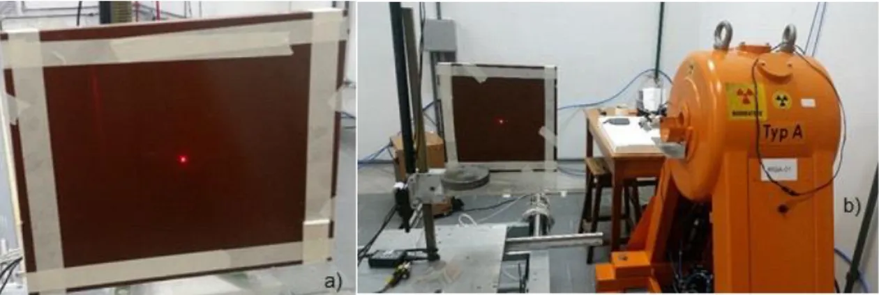
Cesium-137 is a radioisotope originated from nuclear fissions, has a beta decay (β-) and gamma photons associated. It is used as a gamma source with a half-life of 30.07 years and emits gamma photons of 661.7 keV and 283.5 keV, with the occurrence of 85.1% and 5.8x10⁻⁴% of decays, respectively. Figure 1 presents two images of the irradiator containing the source of cesium-137 [11].
Figure 1: Irradiator OB85/1.
2.2. Solid Water Phantom
The solid water phantom used in the tests was built with two solid water plates with dimensions of 30x30x1 and 30x30x2.5 cm³. This phantom has to response similar irradiation beams corresponding to water, with a 1% error. This feature allows working with solid material for tests with water phantoms using radioactive sources and linear particle accelerators [12].
Figure 2 presents a frontal image of the solid water phantom with the light marking of the central point of beam incidence.
2.3. Radiochromic Films
Radiochromic films when exposed to radiation show a darkening proportional to the dose received. As higher is the absorbed dose, as darker they become. The calibration curves of the films are produced to allow the conversion of the darkening values into absorbed dose values. The film used for dose recordings was GAFCHROMIC EBT QD+ which is composed of an active layer with 25 μm thickness.
These films work in a recorded range of 1 mGy just 10 Gy and have a low dependence on beam energy. The film, after being irradiated, were stored in a place without humidity and away from sunlight, so that there was no interference in the chemical reactions of diacetylene compounds [5-7].
2.4. Radiation Tests
The experiments consisted of two process of the solid water phantom irradiation with radiochromic films placed inside. In both processes were realized with a maximum dose value of 2.0 Gy and using a collimator with 2.6 cm keeping the loaded phantom at 1.0 m from the source.
The first test was a frontal irradiation of the phantom with the radiochromic film placed at a depth of 1.0 cm. In the second test, the phantom was irradiated laterally with the film sheet placed in the middle of the plates, to record PDD profile. The central ray of the beam is directed with the help of a laser light.
After the tests, the irradiated films record the dose variation in the center of the field, representing the axial profile of the beam and the size of the field, in order to describe the dose variation. In particular, the variation in beam intensity can occur from the central axis to the edges of the field, according to the beam quality and the collimator opening size and shape.
The calculations about dose were performed based on the half-life of the cesium-137 source in the Calibration and Dosimetry Laboratory (LCD/CDTN), credited by the regulatory agency.
3.1. Dose Profile Graphs
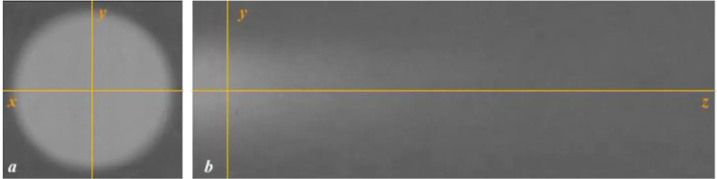
After recording the films in the experiments with the cesium-137 source, the images were properly treated and from them the axial dose profiles were obtained on the x and y axes for the frontal irradiation of the phantom.
The Figure 3a indicates the position of the axes in relation to the axial image of the field. The Figure 3b shows the longitudinal recording film with the positioning of the y-axis at a depth of 1.0 cm. This is the depth at which the film was placed in the frontal irradiation.
The frontal irradiation allows the measurement of the irradiation field size when the gamma beam crosses the collimator hole, and longitudinal irradiation allows to find the dose curve in depth (z-axis).
Figure 3: Scanned films. Frontal (a) and longitudinal (b).
3.2. Percentual Depth Dose (PDD)
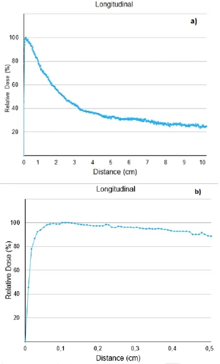
Longitudinal irradiation showed that the dose delivered by the cesium-137 source reached its maximum dose between 1.0 and 1.3 mm, from the target (radiochromic film) and at this point a dose peak was performed as shown in Figure 4. Th reference [13] mentioned a maximum dose in 1.5 mm. The decay of the absorbed dose values occurs with the increase of the distance reached by the gamma beam. The maximum absorbed dose occurred a few millimeters from the surface due to the average photon beam energy being in the keV range. The absorbed dose at a depth of 5.0 cm was 31.7% and at a depth of 10 cm 25.0% of the maximum dose value. The depth dose value
represents the attenuation of photon beam and the dose delivered to the surface, so that there is a sharp drop in the dose with depth. The Figure 4a shows a PDD of cesium-137 source and Figure 4b show a Buildup region.
Figure 4: Relative dose profile in water depth for the source of cesium-137 (a), detail next to the surface (b).
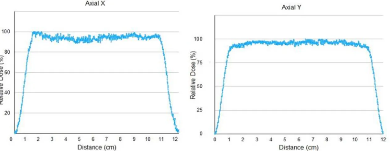
Axial irradiation showed, according to the curves in the Figure 5, a dose variation occurred on the plateaus of axial graphs for x and y axes. These values indicate that the average dose value in the plateau region is 94.58% for the x-axis and 95.81% for the y-axis. The average dose on the plateau, at 1.0 cm depth, is 95.20% of the maximum dose value.
Figure 5: Axial relative dose profiles to 1.0 cm depth in water for the cesium-137 source.
The axial graphs are 12 cm wide and, due to the initial variation in the rise of the curves and the final variation in the descent of the curves, they present a plateau of 9.4 cm. Considering the diver-gent propagation of the beam and the distance from the collimator opening to the phantom, the image generated in the film results in 12 cm in diameter.
Comparing the x and y curves, it is possible to observe the differences in the slope of the curve on the ascent and descent, which is greater on the y-axis. The plateau is slightly concave on the x-axis and convex in the y-axis. These variations could occur due to the source shape, a wire of 1 cm inside a spherical encapsulation, and the distribution of the radionuclide on the wire support, or due to inhomogeneities in the phantom material.
The differences results in relation to the axial graphs of the cesium-137 source field, present an encapsulated source with a possible displacement. The wire is in vertical positions inside the
sphere, which was registered in the output beam. The source is less punctual in the vertical direction, so the climb on the Y axis is steeper.
4. CONCLUSIONS
The photon beam of the cesium-137 irradiator was tested for a collimator with circular opening of 2.6 cm in diameter. The depth variation chart shows that the maximum absorbed dose value occurs very close to the surface of the solid water phantom. This penetration characteristic showed a decrease in dose deposition in the solid water.
These results are a complement to the calibration work of the cesium source previously performed, according to the reference [13], for presentation of the cesium source of the Calibration and Dosimetry Laboratory (LCD) of the Center for the Development of Nuclear Technology (CDTN).
With the irradiations, it was possible to verify the size of the field generated by the cesium-137 source and the depth dose curve and the decay of the gamma beam. It was noticed that, for longitudinal irradiation, the maximum of the dose (2.0 Gy) occurred at a depth between 1.0 and 1.3 mm, being considered as very close to the phantom surface. The axial curves, generated at 1.0 cm depth, demonstrated that the average dose value in the plateau was 95.20% (1.90 Gy).
ACKNOWLEDGMENT
Thanks to the team of Calibration and Dosimetry Laboratory (LCD) of the Nuclear Technology Development Center (CDTN), where the tests were carried out. Thanks to the Radiology Laboratory of the Federal Center for Technological Education of Minas Gerais (CEFET-MG) for the scanner and radiochromic films available. Thanks to CNPq, FAPEMIG, CAPES and CNEN for funding the research.
[1] KHAN, FAIZ M., GIBBONS, JOHN P. The Physics of Radiation Therapy. Fifth Edition. Wolters Kluwer Health. Philadelphia, EUA. 2014.
[2] BALAGAMWALA, Ehsan H., STOCKHAM, Abigail, MACKLIS, Roger, SINGH, Arun D. Introduction to Radiotherapy and Standard Teletherapy Techniques. Ophthalmic Radiation Therapy. Techniques and Applications. Dev Ophthalmol. Basel, Karger, 2013, vol 52, pp 1-14. 2013.
[3] SCAFF, LUIZ A. M. Física da Radioterapia. 1 ed. Sarvier Editora de Livros Médicos Ltda. São Paulo. 1997. 84-86 p.
[4] MOURÃO, A. P.; OLIVEIRA, F. A. Fundamentos de radiologia e imagem. 1 ed. São Caetano do Sul, SP: Difusão, 2009. 343-365 p.
[5] THOMADSEN, Bruce R., KARELLAS, Andrew. Clinical 3D Dosimetry in Modern Radiation Therapy - Imaging in Medical Diagnosis and Therapy. Edited by Ben Midjeen. CRC PRESS. 2018.
[6] IAEA - International Atomic Energy Agency. Dosimetry of Small Static Fields Used in External Beam Radiotherapy - An International Code of Practice for Reference and Relative Dose Determination. Vienna: IAEA, 2017. Technical Reports Series 483. 228 p. [7] DEVIC, Slobodan. Radiochromic film dosimetry: Past, present, and future. Department of
Radiation Oncology, Jewish General Hospital, McGill University. Physica Medica. 122-134. 2011.
[8] DEVIC, Slobodan.; ALDELAIJAN, Saad.; ALZORKANY, Faisal.; MOFTAH, Belal.; BUZUROVIC, SEUNTJENS, Jan.; TOMIC, Nada. Use of a control film piece in radiochromic film dosimetry. Associazione Italiana di Fisica Medica. Elsevier. 2016.
[9] DEVIC, Slobodan, TOMIC, Nada, LEWIS, David. Reference radiochromic film dosimetry: Review of technical aspects. Department of Radiation Oncology, Jewish General Hospital, McGill University. Physica Medica. 541-556. 2016.
[10] STS Steuerungstechnik & Strahlenschutz GmbH. Irradiators - OB85, OB85/1, 85/3. Harxburtteler StraBe 2. 1993.49 p.
[11] CHUL, S. Y. F.; Ekström, L. P.; Firestone, R. B. LBNL nuclear data search. Available at: <http://nucleardata.nuclear.lu.se/toi>. Last accessed: 30.10.2019.
[12] SUN NUCLEAR. Available at: <https://www.sunnuclear.com>. Last accessed: 30.10.2019. [13] THORAEUS, R. Cesium 137 and its Gamma Radiation in Teleradiotherapy. Acta
Radiologica. p 385-395. 1961.
[14] PORTELA C. F. T.; SANTOS F. S.; ALONSO T. C.; MOURÃO A. P. Caracterização e Calibração de Filme Radiocrômicos para Dosimetria de Feixe Gama. In: Quarta Semana de Engenharia Nuclear e Ciências das Radiações – IV SENCIR, 2018, Belo Horizonte, MG. Escola de Engenharia – Universidade Federal de Minas Gerais, 2018. p. 45-50.