FINITE ELEMENT ANALYSIS OF
SLURRY INFILTRATED FIBROUS
CONCRETE TWO WAY SLABS
SUBJECTED TO FLEXURAL LOADING
K.RAJASEKHAR Assistant Professor Department of Civil Engineering
College of Engineering Andhra University Visakhapatnam - 003. Email: [email protected]
Dr. H.SUDARSANA RAO Director, (ICS) & Professor of Civil Engineering,
J.N.T. University, Anantapur Anantapur
Andhra Pradesh.
Email: [email protected]
Dr. VAISHALI.G.GHORPADE Associate Professor of Civil Engineering,
J.N.T.U.A College of Engineering Anantapur
Andhra Pradesh.
Email: [email protected]
Abstract:
Slurry Infiltrate Fibrous Concrete (SIFCON) is a new high performance and advanced material and can be considered as a special type of steel fiber reinforced concrete (SFRC). This paper describes the development of two – way slab model to predict the non-linear load-displacement behavior of SIFCON slab subjected to pressure loading. Slabs with 8%, 10% and 12% for different edge conditions have been modeled in Finite elements and verified with experimental values. The results of the analysis show that the SIFCON slabs with 12% fibre volume fraction exhibit excellent performance in flexure among other slabs. The FEM results have agreed closely with the experimental deflection values for the loadings considered.
Key Words: Slurry Infiltrated Fibrous concrete (SIFCON), Finite Element Method (FEM), Model Slabs, Deflection, Non-linear Behavior.
1. Introduction:
Recently, there has been a growing interest in the use of high-performance fibre-reinforced concrete (HPFRC) for structural elements. This is because most of the rheological, mechanical and durability properties of these materials are better than those of conventional Fibre Reinforced Concrete.
which has been successfully used in structural rehabilitation, is slurry infiltrated fibre concrete (SIFCON). Slurry infiltrated fibrous concrete (SIFCON) is one of the new advanced material and it can be considered as special type of fibre reinforced concrete (FRC). Normally, FRC contains 1-3% fibres by volume, where as SIFCON contains 6-20 % of fibres. The other major difference is in the composition of the matrix. SIFCON is relatively a new HPFRC in which formwork molds are filled to capacity with fibres and the resulting fibre network is infiltrated by cement-sand based slurry (grout). Even though, SIFCON is a recent construction material, it has found applications in the areas of pavements repairs, repair of bridge structures, safe vaults and defense structures due to its excellent energy absorption capacities.
It is observed from the review that very little research is carried out to study the behavior of SIFCON
slab elements using analytical methods. With this view, an analytical investigation had been carried out using FEM software in the present work to understand the flexural behaviour of SIFCON slab panels.
Experimental based testing has been widely used as a means to analyze individual elements and the
effects of concrete strength under loading. The use of finite element analysis to study these SIFCON slab components will be quite interesting. Despite its long history, the finite element method continues to be the predominant strategy employed by engineers to conduct structural analysis. A reliable method is needed for analyzing structures made of SIFCON concrete, a complex but rare ingredient in most of the structural components. As an effective alternative to expensive experimentation, this study has been conducted to evaluate the plausibility of finite element analysis of SIFCON slabs.
This paper is proposed to study the response of slurry infiltrated fibre concrete slabs using finite element analysis to understand their load-deflection response under pressure loading. A slurry infiltrated fibre concrete slab model will be developed using FEM and the results will be compared to experimental data in this paper. Slabs with different edge conditions i.e. 8%, 10% and 12% volume fraction of fibre are analysed using FEM. NISA, a general purpose Finite Element Software, has been employed for this purpose. Solid elements have been used to develop the slab model and the accuracy of the model has been verified with experimental values.
2. Literature review:
Slurry infiltrated fibrous concrete (SIFCON) is relatively new composite material that differs from
relatively new material due to its high strength and ductility characteristics it has potential applications such as rehabilitation of bridge decks, pavement rehabilitation, explosive resistant containers for storing materials that could accidentally explode, earth quake retaining structures, security vaults and refractory applications, etc., due to its excellent energy absorption capacities [Victor, 2002], Schneider, 1992]. Singh et al. [2000] studied the stress-strain behavior in compression and tension by preparing SIFCON with 10% volume fraction of fibres by adding fly-ash in the matrix. Deaton [2005] developed a software called NLFEAS (Non-Linear Finite Element Analysis of Slabs) to predict the three dimensional behavior of reinforced concrete slabs of different grades and boundary conditions under gravity loads. Smadi and Belakhdar [2007] have developed a nonlinear finite element code to suite the analysis of normal and high strength concrete slabs. A software called NLFEAS (Non-Linear Finite Element Analysis of Slabs) was developed to predicate and study the three dimensional response of reinforced concrete slabs of different grades, variables and boundary conditions under monotonically increasing loads. Proper numerical material models for cracked concrete were incorporated in the analysis.
3. Development of Finite Element Model
Development of a finite element model for predicting the load deflection response of SIFCON slab elements involve various stages which are addressed in the following sections.
3. 1. Methodology
The load – deflection response of the slab has been modelled by the finite element method. To study the effect of volume fraction of fibre in modeled slab, two categories of slab, viz., slab with all fixed edges and all simply supported edges are considered. For each category experimental values for young’s modulus, E, yield
stress,
y Poisson’s ratio,
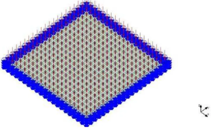
for different volume fraction of fibre has been used from Table No.1. For thestudy of non-linear response of slab beyond the elastic limit stress –strain data from experimental work has been used. The region of the domain and boundary conditions of the modeled slab for the both the categories are as shown in Figure No.1 and Figure No.2. The details of test program are presented in Table No. 2.
.
Figure No. 1: Finite element discretization for the SIFCON slab fixed on all its edges
Table No.1: Material properties
S.No Property Value
8 % 10% 12%
1 Young’s modulus 1.430x 10⁴ 1.430x 10⁴ 1.430x 10⁴
2 Poison’s ratio 0.23 0.23 0.23
3 The yield stress 1.5N/mm2 1.5N/mm2 1.5N/mm2
Table No.2: Details of test programme
S.No. Slab Type Slab Designation Percent volume of
fibres
1.
SIFCON slab with all four edges fixed
SIF0S4F-8 8
2. SIF0S4F-10 10
3 SIF0S4F-12 12
4 SIFCON slab with all four edges
simply supported
SIF4S0F-8 8
5 SIF4S0F-10 10
6 SIF4S0F-12 12
3.2. Finite element analysis
The SIFCON slab is modeled using 3D solid elements. The developed model can simulate the all the possible support and load conditions that usually occur in normal building slabs. To estimate the number of elements in each direction of the slab, studies have been conducted which give a constant deflection with increasing number of elements. These elements have three degrees of freedom per node. To represent the support condition, proper boundary conditions have been used. When the support is fixed, all the degrees of freedom (Ux, Uy, Uz,) have been restrained and for simple support case only vertical degrees of freedom (Uz) have been restrained. Load is applied on the surface of the elements as pressure load which is ultimate load of the panel from the experimental study.
The slab selected for analysis has a dimension of 600 mm x 600mm, and a thickness of 50mm. It is
discritised using solid element having size 30. A uniform pressure of 0.192N/mm2, which is close to the ultimate
load of the slab, is applied on the surface of the elements. This load is applied incrementally as 100 load steps and Newton Raphson’s method has been used to facilitate the non-linear analysis for solution convergence. In non-linear static analysis, a von-mises yield criterion with elastic piece wise linear hardening curve is used in this slab model analysis. In the simply supported case, one fourth of the model with symmetric boundary conditions on the two edges has been considered for the analysis which also represents the full model analysis.
The solid elements representing the slab were 2000 brick elements and 2646 nodes with three degrees of freedom per node. The details of the various model slabs are presented in Table No.3. The numerical material properties are given in Table No.1.
3.3 Results and Discussions
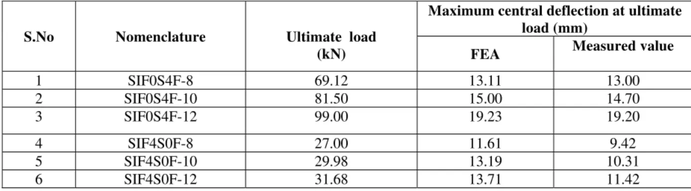
For validation purpose, finite element analysis has been carried out on FE modeled SIFCON slab and the results have been compared well with the measured values presented in Table 3 obtained by experimentation [Rao and Ramana, (2005)].
Table No.3: Central deflection values for various square plates with uniform load for different percentage volumes of fibre fraction
S.No Nomenclature Ultimate load (kN)
Maximum central deflection at ultimate load (mm)
FEA Measured value
1 SIF0S4F-8 69.12 13.11 13.00
2 SIF0S4F-10 81.50 15.00 14.70
3 SIF0S4F-12 99.00 19.23 19.20
4 SIF4S0F-8 27.00 11.61 9.42
5 SIF4S0F-10 29.98 13.19 10.31
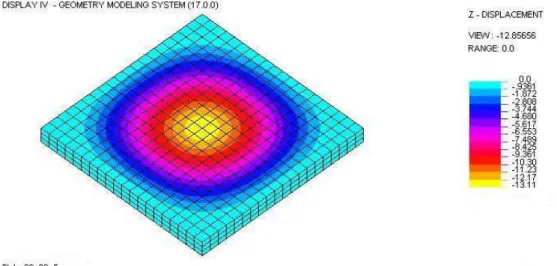
It is found that the results obtained from the experimentation are comparing well with the results obtained from the analytical model solutions. Z-displacement of the SIFCON model slab for both the edge conditions are shown in Figure Nos.3. and 4. From the figures, the maximum deflection is at the mid-span. Whereas in the case of slab having fixed edges on all its sides a maximum deflection of 19.23mm for SIF4S0F-12 which is even higher than the other two types of volume fraction of fibre slabs is noted.
Figure No.3: Z-Displacement for FE modeled SIFCON slab with fixed edge condition
Figure No.4: Z-Displacement for FE modeled SIFCON slab with simply supported edge condition
Figure No.5: Comparison of Load – Deflection response of SIF0S4F Slabs
Figure No.6: Comparison of Load – Deflection response of SIF4S0F Slabs
From the Figures, it can be seen that the load deflection response is non-linear at any given load. It can be observed that SIFCON slabs with 12% volume fraction of fibre exhibit greater stiffness at any given load. From this it is observed that the SIF4S0F-12 and SIF0S4F-12 slab models show higher performance than the other slab specimens.
(a)
(c )
Figure No.7: Load – Deflection response of SIFCON Slabs with various boundary conditions: (a) Volume of fibre fraction = 8%; (b) Volume of fibre fraction = 10%; (c) Volume of fibre fraction = 12%
The analysis of results shows good agreement between analytical values and experimental values. From the curves, it is observed that the slabs with 12% volume fraction of fibre show higher performance than the other slab specimens indicating that it can resist high load. Among SIFCON slabs, the stiffness increases with increase in percentage of fibres. This increase in stiffness can be attributed to the greater stiffness characteristics of steel fiber.
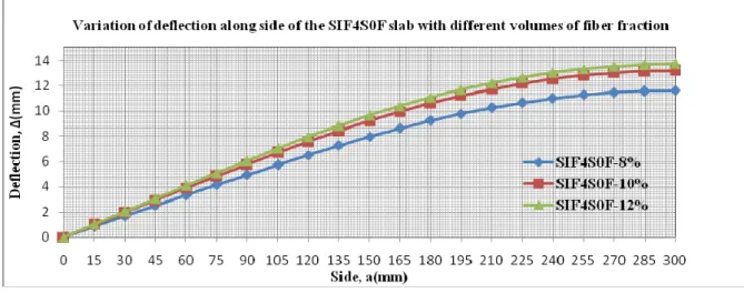
Figures 8 and 9 illustrate deflections along or across the mid span for the ultimate pressure pattern for SIF0S4F and SIF4S0F SLABS with different volumes of fibre fraction. The results illustrated in the figures show that at the ultimate pressures, the slabs having fixed boundary edge condition, the slab with 8% volume fraction of fibres had smaller deflection than the slab having same edge boundary conditions with other volumes of fibre fraction. Similar trend has been observed for slabs having simply supported edge boundary condition with 8%, 10% and 12% volumes of fibre fraction.
Figure NO.9: Deflection variation across mid span of slab for simply supported boundary edge condition
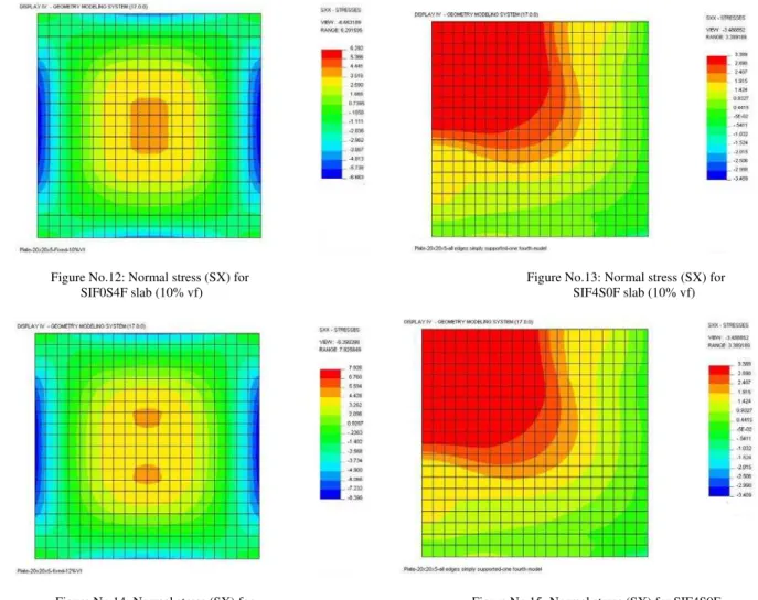
Figures 10 to 15 show the Normal Stresses at the bottom face for SIFCON slabs having different boundary conditions (SIF0S4F, SIF4S0F) with different volume fractions of fibre. Normal stresses at the bottom face at pressure equal to ultimate pressure were calculated throughout the slabs.
Normal stresses for SIFCON slabs having different boundary conditions (SIF0S4F, SIF4S0F) with different volume fractions of fibre have nearly same behaviour. Figure shows the tension stresses spread along large area in mid zone of the SIF0S4F slab having fixed boundary condition with 8% volume fraction of fibre. While in the simply supported case, one fourth of the model with symmetric boundary conditions on the two edges has been considered for the analysis which also shows the spread towards corner at bottom surface. This behaviour is same for all slabs having different volume fractions of fibre i.e. 10% and 12% respectively.
Figure No.10: Normal stress (SX) for Figure No.11: Normal stress (SX) for SIF4S0F
SIF0S4F slab (8% vf) slab (8% vf)
Figure No.12: Normal stress (SX) for Figure No.13: Normal stress (SX) for
SIF0S4F slab (10% vf) SIF4S0F slab (10% vf)
Figure No.14: Normal stress (SX) for Figure No.15: Normal stress (SX) for SIF4S0F
SIF0S4F slab (12% vf) slab (12% vf)
4. Conclusions
The finite element technique has been used to model the behaviour of SIFCON slabs. NISA was used to model all the test specimens. The NISA model accommodates material non-linearties and yielding of slab nicely. The experimental results compared well with the values obtained from FE analysis for the various SIFCON slabs with different volume fraction of fibre. The non-linear analysis model described in this study was shown to predict with reasonable agreement the load – deflection response of slabs using SIFCON matrix. The load –deflection response of the slabs is observed to be non-linear based on FE analysis. The volume fraction of fibre has significant effect on load – deflection response of SIFCON slabs. The SIFCON slabs with high percentage of volume fractions of fibres behaved better than those containing less percentage fraction of fibres. A variation of 10 to 25% in the deflection values has been observed for the both the types of slabs by FEM indicating that variation of volume fraction of fibre influences the performance of slab. Using finite element analysis by NISA, the solution of SIFCON slabs become simple, easy to analyse all types of slabs.
References:
[1] Agur,P and Kendzilak, John. 1986. Flexural behavior of slurry infiltrated fiber concrete (SIFCON) and using condensed silica fume,
fly ash, silica fume, slag ash and natural pozzolana in concrete. SP-91, American Concrete Institute, Detroit, 86, Vol. 2, pp 1215-1219.
[2] Deaton, J.B. 2005. A Finite Element Approach to Reinforced Concrete Slab Design, M.Sc. Thesis, School of Civil and Environmental
Engineering, Georgia Institute of Technology, 170.
[3] Josifek, C., and Lankard, D. 1987. SIFCON: Slurry infiltrated fibre concrete. Fibre reinforced concrete Int. Symp., Madras, Vol.2, pp
7.15-7.23.
[4] Lankard DR.1985. Slurry infiltrated fibre concrete (SIFCON) properties and applications. Very high strength cement-based
composites, Material Research Society, 42, 227-86.
[5] Lankard DR.1984. Slurry infiltrated fibre concrete (SIFCON), Concrete International, 12, 44-47.
[6] Naaman, A.E. and Homrich, J.R. May-June 1989. Tensile stress strain properties of SIFCON. American Concrete Institute Material
Journal, Vol. 86, pp. 227-233.
[7] Parameswaran V.S, Krishnamoorty T.S, Balasubramanian K. 1990. Behavior of high volume fibre cements mortar in flexure, Cement
[8] Rao HS, Ramana NV and K.Gnaneswar. 2009. Behavior of restrained SIFCON two- way slabs. Part 1: Flexure, Asian Journal of Civil Engineering (Building and Housing), Vol.10, No. 4, pp. 427-449.
[9] Rao HS, Ramana NV. 2005. Behavior of slurry infiltrated fibrous concrete (SIFCON) simply supported two- way slabs in flexure,
Indian Journal of Engineering and Materials Science, 12, 427-33.
[10] Naaman.A.E., Otter D., Najm. H. 1992. “Elastic modulus of SIFCON in tension and compression.” ACI Mat Journal. 6, 603-613.
[11] Homrich, J.R., Naaman, A.E. 1987. Stress-strain properties of SIFCON in compression.” Fibre Reinforced Concrete Properties and
Applications, ACI SP- 105, 244-251.
[12] Naaman, A.E., Homrich J.R. 1989. “Tensile stress-strain properties of SIFCON.” ACI Mat J., 3, 244-251.
[13] ASCE. 1982. Task Committee on Finite Element Analysis of Reinforced Concrete Structures. State-of-the-Art Report on Finite
Element Analysis of Reinforced Concrete, ASCE Special Publications.
[14] Ngo D, Scordelis AC.1967. Finite-element analysis of reinforced concrete beams. ACI J: 152-63.
[15] Suidan, M.T. and Schnobrich, W.C.1973. "Finite Element Analysis of Reinforced Concrete". Journal of the Structural Division,
ASCE, Vol. 99, No. ST10, pp. 2109-2122.
[16] [16] Victor. C.Li. 2002. Large volume High performance applications of fibres in civil engineering. Applied Polymer Science, 83, 660
-686.
[17] Schneider. B.1992. Development of SIFCON through applications High Performance Fibre Reinforced Cement Composites, (E & FN
Spoon, London).
[18] Bhupinder, Praveen Kumar & Kaushik. S.K., 2000. Journal of structural Engineering, No.1, 28, 17-26.
[19] Smadi.M.M. and Belakhdar. K.A. 2007. Development of Finite Element Code for Analysis of Reinforced Concrete Slabs, Jordan