Abstract
Numerical modeling of fracture failure is challenging due to vari-ous issues in the constitutive law and the transition of continuum to discrete bodies. Therefore, this study presents the application of the combined finite-discrete element method to investigate the fracture failure of reinforced concrete slabs subjected to blast loading. In numerical modeling, the interaction of non-uniform blast loading on the concrete slab was modeled using the incorpo-ration of the finite element method with a crack rotating approach and the discrete element method to model crack, fracture onset and its post-failures. A time varying pressure-time history based on the mapping method was adopted to define blast loading. The Mohr-Coulomb with Rankine cut-off and von-Mises criteria were applied for concrete and steel reinforcement respectively. The results of scabbing, spalling and fracture show a reliable prediction of damage and fracture.
Keywords
Fracture, the combined finite-discrete element method, reinforced concrete slab, blast loading
Fracture Failure of Reinforced Concrete Slabs Subjected to Blast
Loading Using the Combined Finite-Discrete Element Method
1 INTRODUCTION
Blast loading from an explosion is defined as a large-scale, rapid and sudden release of energy that able to jeopardize any targets at catastrophic damage. Therefore, blast loading is known as the most destructive dynamic load that a structure may experience (Xu and Lu, 2006). If an explosion occurs in close proximately to the structure, blast loading that travel as shock wave will setup an internal compressive stress wave and subsequently produce shattering effects on the material. This leads to spalling at the surface facing the explosion and scabbing at the rear end. Thereafter, small
Z. M. Jaini a Y. T. Feng b D. R. J. Owen c S. N. Mokhatar d
a Jamilus Research Center, University
Tun Hussein Onn, 86400 Johor, Malaysia [email protected]
b,c Zienkiewicz Centre for Computational
Engineering, Swansea University, SA18EN Wales, United Kingdom [email protected]
d Department of Structure and Material
Engineering, University Tun Hussein Onn, 86400 Johor, Malaysia
http://dx.doi.org/10.1590/1679-78252362
Latin American Journal of Solids and Structures 13 (2016) 1086-1106
fragments from the failure zone propagate through the thickness of the structure. For reinforced concrete structures, this normally results in a large number of fractures over a range of size and velocity, which can cause serious consequences. The fracture initiation is fully dependent on the structure form, material properties and the condition of blast loading. The fracture can be directly observed during the separation of concrete at the scabbing zone. However, spalling also produces concrete fragments due to high-intensity of blast loading particularly that happen under contact detonation.
Fracture is well known induced by the growth and coalescence of cracks. Wang et al. (2009) stated that there is a correlation between the fracture size distribution and the crack size function. Some fraction of energy from blast loading transferred to the concrete fragments, hence the fracture travels with high velocity. Fracture velocity of disengaged elements may be up to 60m/s (Cormie et al., 2009). Currently, there is very limited available information about the fracture and its size dis-tribution resulting from spalling and scabbing of reinforced concrete structures loaded by blast load-ing. A series of blast testing were carried out by Razaqpur (2007), Schenker et al. (2008), Silva and Lu (2009), Kim et al. (2010), Alonso et al. (2011) and others, but these studies only examine the dynamic responses and damage behavior of concrete structures. Wu et al. (2009) conducted an ex-perimental study to determine the fracture size and fragment distributions of reinforced concrete slabs. In addition, Gronsten and Forsen (2007) conducted a field test of an explosion using a high speed camera to capture the fragment size and ejection velocity. The high energy releases and sig-nificant short duration of blast loading make the observation of fracture very unlikely and difficult to be conducted. Until recently, there is no precise method that can be employed to estimate the ascertaining of fracture size.
The phenomenal successes of the finite element method in numerical modeling of concrete struc-tures under dynamic loadings have led to the prestigious works in the prediction of structural re-sponses and damage mechanisms. However, this established method may unable to produce con-vincing results of post-failures, particularly fracture. Previous works by Luccioni and Luege (2006) and Elsanadedy et al. (2011) suggested the application of the finite element method to model the local and global damage of concrete structures subjected to high loading rate. These studies were relied on the continuum failure which not really represents the mechanism of fracture and its post-failures. On the other hand, Rabezuk and Eibl (2006) introduced a meshless method to model the post-cracking of concrete. Although, the meshless method has proven able to produce elegant results in multi-fracturing, but still facing major problems in the dynamic responses. Since many studies on the concrete structures under blast loading concentrate on the localized responses and post-failures, hence, the continuum failure based on the stress distribution is not longer sufficient to represent such mechanisms. The evolution of the finite element method has revealed the consideration of the discrete failure that can be achieved through a special algorithm so-called the combined finite-discrete element method.
Latin American Journal of Solids and Structures 13 (2016) 1086-1106
and hence provide accurate numerical modeling of fracturing and particulate flow. Originally, the combined finite-discrete element method has been applied by Steadm et al. (2004), Eberhardt et al. (2004) and Pine et al. (2006) to solve the geo-mechanics problems. In the concrete structure field, Munjiza et al. (2000), May et al. (2006), Frangin et al. (2006), Smoljanovic et al. (2013) and Seman et al. (2013) used this method to model reinforced concrete structures under high loading rate, sub-sequently represent the cutting-edge in the modeling of quasi-brittle materials. Meanwhile, this pa-per presents numerical modeling of fracture failure of concrete structures under blast loading using the combined finite-discrete element method. Several main challenges in numerical modeling of con-crete structures under blast loading using the combined finite-discon-crete element method are also ad-dressed.
2 FRACTURE MODELING
The combined finite-discrete element method uses a similar algorithm as in the explicit dynamic finite element method with additional parameters for the discrete element insertion. From the basic equation that governs the linear dynamic response of any structural system of finite elements, given by:
( )
( )
( )
ext( )
n n n n
Mu t +Cu t +Ku t = f t (1)
The spatially discretised form of the dynamic equilibrium equations at time tncan be rewritten
as:
( )
( )
ext( )
int(
( )
)
n n n n
Mu t +Cu t =f t -f u t (2)
where M, C and K represent the global mass, damping and stiffness matrices respectively. The f.int is
the vector of the internal resisting forces, and f.extis the velocity applied forces. The standard
nota-tions u, u and u signify the acceleration, velocity and displacement vectors in the global domain.
The subscript n implies a quantity at time tn. In the context of dynamic time integration for
non-linear problems, the governing equation generalizes the stiffness dependent elastic forces to include both geometric and constitutive nonlinearities to provide internal forces with the structure (Cot-trell, 2002).
Latin American Journal of Solids and Structures 13 (2016) 1086-1106
model which enforces coincident rotation of the principal axes of orthotropy and the principal strain
axes (Bhattacharjee and Leger, 1994; Guzina et al., 1995).
However, when dealing with concrete in the combined finite-discrete element method, the com-monly accepted Rankine and rotating crack models can be used to simulate crack formation within a continuum description under tensile conditions. The advantage of applying these models is that it has been extended to include rate dependent effects that governed by tensile strength and aniso-tropic softening. Therefore, the modeling of crack formation and fracture become very much an engineering approach. The initial failure for the Rankine and rotating crack models can be repre-sented by:
(
)
(
)
0i t
g = s t+ D -t f t + Dt = (3)
where σi is the principal stress invariant, and f.t is the tensile strength of concrete. After the initial
yield, the rotating crack formulation represents the anisotropic damage evolution by degrading the elastic modulus in the direction of the major principal stress invariant (Owen and Feng, 2001; Rockfield, 2009; De Borst et al., 2012), and the stress can be evaluated using the following equation:
(
1)
nn E n
s = -w e (4)
where w is the damage parameter and is directly dependent upon the current state of strain
soften-ing within the crack band, and εn is the local strain at the local coordinate system associated with
principal stress. The damage parameter is dependent on the fracture energy denoted by:
2 IC f
K G
E
= (5)
where KIC is the critical stress intensity factor, and E is the elastic modulus of concrete. After the
onset of failure, developing damage degrades the elastic modulus and the damaged elastic modulus, E.D is given as:
(
1)
D
E = -w E (6)
Latin American Journal of Solids and Structures 13 (2016) 1086-1106
a) b) c)
Figure 1: Crack insertion procedure, a) initial state, b) through element, or c) along element boundary (Klerck et al., 2004).
Fracture development and potential material degradation into discrete fracture require a special treatment of mechanical forces on the contact interfaces. In the combined finite-discrete element method, the contact interaction laws are adopted in term of a penalty method. Strength parameters on the fracture interface are defined in term of cohesion and friction angle based on a linear Mohr-Coulomb criterion (Vyazmensky et al., 2007). Following the insertion of a discrete fracture, the crack surface assumes a frictional contact response governed by contact parameters based on the theory of the contact surface conditions. The contact parameters are introduced to control the ele-ment separation from finite eleele-ment to discrete eleele-ment and in assuring the maintenance of energy balance during this transition period.
3 BLAST LOADING
When an explosive detonates, the blast wave is initiated by the rapid release of a large amount of energy. The blast wave expanding spherically and propagates under compressed air within a fraction of second. The time of blast wave moves outward from the detonation source to the rigid surface is known as the time of arrival. The blast wave then loaded on structure as an incident overpressure that rises abruptly to a peak value and decays exponentially to the ambient pressure within the short duration of positive phase. The overpressure continues to decline and drop below the ambient pressure so-called the negative phase of blast wave. After acting on the surface of structure, the incident over-pressure is transformed as a reflected overover-pressure and travel back through air that has been heated and compressed by the passage of preceding blast wave. Two distinct of the incident and reflected overpressures that act simultaneously are known as the static overpressure. Besides that, the blast wave is also accompanied by the dynamic pressure known as wind blast.
In numerical modeling, the Jones-Wilkins-Lee equation of state is widely used to represent blast wave. Blast wave is transferred to the surface of structure using coupling of Arbitrary Lagrangian-Eulerian model for multi-material fluids, and the Lagrangian model for structure (Souli et al., 2000; Bouamoul and Dang, 2008; Chafi et al., 2009; Deng and Jin, 2009). The Jones-Wilkins-Lee equation of state defines the pressure of explosion as:
(
)
1 21 2
, 1 R V 1 R V e
p e V A e B e
R V R V V
w - w - w
æ ö÷ æ ö÷
ç ÷ ç ÷
= ççç - ÷÷ + ççç - ÷÷ +
Latin American Journal of Solids and Structures 13 (2016) 1086-1106
where p is pressure, e is internal energy, V is the specific volume, while A, R1, B, R2 and are all
material constants than can be referred in Dobartz (1981) and Zhou et al. (2008). The Jones-Wilkins-Lee is generally considered as a pure empirical equation of state with a non-physical coeffi-cient considered to be constant. As a result, the exponential terms can give unrealistic behaviour at high pressures. The Jones-Wilkins-Lee equation of state is normally used for modeling the pressure in application involving elastic models, isochoric plasticity and visco-plasticity models. Therefore, Jaini and Feng (2011) found that this equation of state cannot be used with compressible models like Rankine, rotating crack, Mohr-Coulomb and Drucker-Prager models.
Alternatively, the mapping method is the most convenient approach to model the blast loading. The determination of blast loading involves the simultaneous calculation of the incident overpres-sure, the reflected overpressure and wind blast. All parameters are primarily dependent on the amount of energy released by an explosion in the form of blast wave and standoff distance. The incident overpressure occurs after the blast wave hits the structure. It is basically determined as the pressure-time history using Friedlander’s formula as shown in Equation (8). The reflected overpres-sure can be determined based on Rankine's formula as depicted in Equation (9), while Ngo et al. (2007) suggested Equation (10) to determine wind blast.
( )
1 a exp ai a s
d d
t t t t
P t P P b
t t
æ - ö÷ æ - ö÷
ç ÷ ç ÷
= + ççç - ÷÷ ççç- ÷÷
è ø è ø (8)
( )
2( )
7 4( )
( )
7a s
r s
a s
P P t P t P t
P P t
é + ù
ê ú
= ê ú
+
ê ú
ë û (9)
( )
( )
( )
2 5 2 7 s q s a P t P tP t P
é ù
ë û
= é ù
+
ë û (10)
where Pi is the incident overpressure, Pa is the ambient pressure typically taken as 101kPa, Psis the
peak overpressure that can be obtained using various graphical and empirical methods, ta is time
arrival, td is the positive duration of blast loading, and b is a decay coefficient. Meanwhile, Prand
Pq refer to the reflected overpressure and wind blast respectively.
4 MODELING OF REINFORCED CONCRETE SLAB SUBJECTED TO BLAST LOADING
Latin American Journal of Solids and Structures 13 (2016) 1086-1106
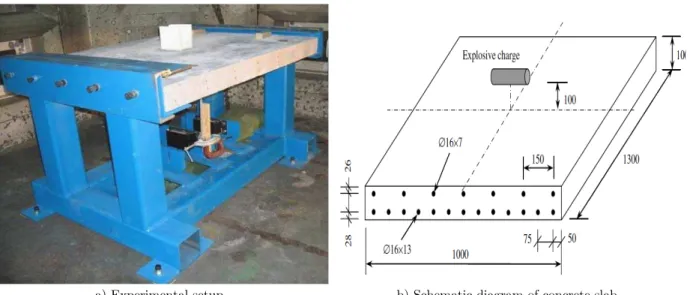
a) Experimental setup b) Schematic diagram of concrete slab
Figure 2: Experimental study of concrete slab under blast loading (Zhou et al., 2008).
The concrete slab was divided into three volumes and discretized with unstructured 4-noded solid tetrahedral element. Figure 3 shows the finite-discrete element model which is composed of 42481 meshes. The tetrahedral element was used since it can be generated automatically using the advancing front or Delaunay mesh generation technique, geometrically versatile and fairly represent a complex three-dimensional domain. Moreover, this type of element is desirable from the consideration of the number of nodes in conjunction with the number of degree-of-freedom that have the direct impact on the solution time, especially in the modeling that involve crack formation under high loading rate and characterized by extremely high strains (Timothy et al., 1991; Owen et al., 2007).
Figure 3: Finite-discrete element model of reinforced concrete slab.
Latin American Journal of Solids and Structures 13 (2016) 1086-1106
with the definition of the material stiffness. Material stiffness is represented by the flexural and shear rigidities in term of the elastic material characteristics and geometric properties such as the moment of area, the cross-sectional area and the effective shear area. On the other hand, the local effects such as gradual bond deterioration, dowel action and pullout effects were represented indi-rectly by the degradation of the surrounding continuum. The perfect bond was assumed between the steel reinforcements and concrete material. This assumption of compatibility of displacement and strains between steel and concrete allows the reinforcement to be treated as an integral part of the three-dimensional finite-discrete element model (Cerveta and Hinton, 1986).
4.1 Material Models
In order to achieve both continuum and fracture failures, two types of plasticity models namely the non-linear material model and brittle-fracture model were employed. The non-linear material model involves the isotropic Mohr-Coulomb with Rankine cut-off for concrete and von-Mises for steel rein-forcement. It should be noted here that the limitation of the isotropic Mohr-Coulomb with Rankine cut-off is that the deformation analysis requires a flow rule to determine the orientation of the strain-increment vector with respect to the yield condition (Labuz and Zang, 2012). The compres-sion failure is a notoriously difficult one to be obtained as the non-linear material model has no cap on its shear strength and normal stress. Meanwhile, the brittle fracture model was defined in the concrete material using the rotating crack model with rate dependency. The use of non-linear mate-rial and brittle fracture models are based on a traditional Lagrangian approach that has been en-hanced by a number of numerical procedures to enable effective simulation of a combination of large strain and high pressure in quasi-brittle materials.
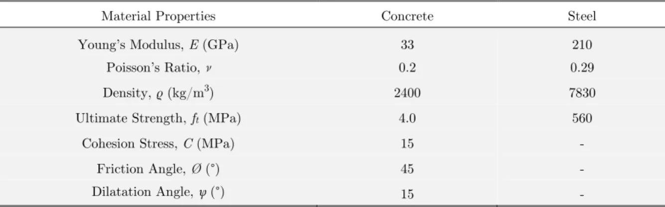
The material properties for concrete and steel reinforcement can be referred in Table 1. The compressive strength, tensile strength and density of concrete and steel were followed the data that provided by Zhou et al. (2008). Meanwhile, the Young’s modulus of concrete was simply calculated using the following equation:
4.773 c
E = f (11)
where E is the Young’s modulus, and fc is compressive strength of concrete taken as 50MPa. The
fracture energy of 100N/m was defined on concrete. This value of fracture energy was calculated using an equation proposed by Oh et al. (1999):
56.24t a
f
f d G
E
= (12)
where Gfis the fracture energy, ftis tensile strength, and da is the size of aggregate considered as
Latin American Journal of Solids and Structures 13 (2016) 1086-1106
Material Properties Concrete Steel
Young’s Modulus, E (GPa) 33 210
Poisson’s Ratio, ν 0.2 0.29
Density, ρ (kg/m3) 2400 7830
Ultimate Strength, ft (MPa) 4.0 560
Cohesion Stress, C (MPa) 15 -
Friction Angle, Ø (°) 45 -
Dilatation Angle, (°) 15 -
Table 1: Material properties of concrete and steel reinforcement.
Strain Cohesion Stress, C (MPa)
Friction Angle, Ø (°)
Dilatation Angle, (°)
0.0 15 45 15
0.03 15 45 5
1 15 45 0
Table 2: Hardening properties of concrete.
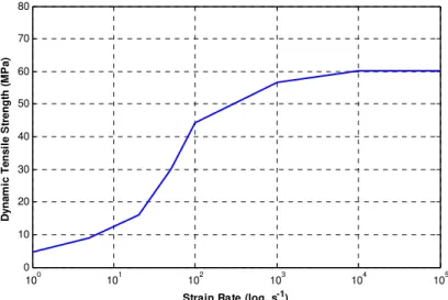
In addition to the required data in the fracture failure, the rate dependency of concrete as can be seen in Figure 4 was also introduced through the use of the dynamic tensile strength with re-spect to the strain rate effects. The dynamic increase factor was used to increase the tensile strength
of concrete at zero strain rate until 105s-1, instead of many previous studies just adopted the strain
rate effects up to 103s-1. Data of the dynamic increase factor for the tensile strength of concrete was
obtained from various experimental and numerical based literatures, as example Malvar and Ross (1998), Lambert and Allen (2000), Brara et al. (2001) and Schuler et al. (2006). It was identified that the dynamic increase factor for strain rate of 1s-1, 5s-1, 20s-1, 50s-1, 102 s-1, 103 s-1 is 1.3, 2.5, 4.5,
8.5, 12.5 and 16.0 respectively, and remain constant at 17.0 for strain rate within the range of 104 s
-1 to 105s-1. The dynamic tensile strength can be obtained by multiplying the tensile strength with
Latin American Journal of Solids and Structures 13 (2016) 1086-1106
100 101 102 103 104 105
0 10 20 30 40 50 60 70 80
Strain Rate (log, s-1)
D
y
na
m
ic
Te
n
s
il
e
S
tr
e
ng
th
(
M
P
a
)
Figure 4: Strain rate dependency of concrete.
4.2 Contact Surface and Discrete Element Data
The contact interaction of discrete bodies was based on the edge-to-edge algorithm. The contact resolution was provided through the linear penalty method as suggested by Yu (1999). An addi-tional contact damping is also included through the use of velocity/momentum-dependent damping and global damping, set at 60% and 5% respectively. Others global discrete element contact data are listed in Table 3. These contact surface and discrete element data were initially followed the recommendation of Bere (2004) and Rockfield (2009). In general, the value of discrete element con-tact field is normally 10% to 20% of the minimum side length of the finite elements in the mesh system. Field sizes that are too small may result in penetration of a node through an element. The discrete contact zone is the size of buffer zone for contact detection. This is used to locate nodes close to any surface during contact detection and the ideal size should be equal to the average size of the side lengths of the finite element mesh.
No. Parameter Value
1 Discrete element contact damping (%) 60.00
2 Adaptive dynamic relaxation damping (%) 5.00
3 Discrete element contact field, lf (mm) 0.02
4 Discrete element contact zone, lb (mm) 0.75
5 Smallest discrete element, ls (mm) 0.00
6 Global normal penalty coefficient, αn(GPa) 300.00 7 Global tangential penalty coefficient, αt (GPa) 30.00
8 Normal contact stress, Sn (GPa) -10
9 Initial tension cut-off contact stress, So 0
10 Coulomb friction coefficient, μ 0.2
Latin American Journal of Solids and Structures 13 (2016) 1086-1106
Meanwhile, the smallest discrete element is a compulsory data for fracturing model. If the ele-ment size becomes smaller than this eleele-ment, then the fracture will only occur between the eleele-ment boundaries and not through the element. By setup the smallest discrete element equal to zero, the fracture can be obtained without relying on the specific size. In the dynamic-transient problems, the value of normal penalty coefficient is typically in the range of 0.5 to 2.0 times of Young's modulus. The tangential penalty is normally taken as the friction coefficient multiple with Young's modulus or usually taken as an order of magnitude approximately 0.1 of the normal penalty coefficient. It should be noted that the contact penalty coefficients applied in the concrete slab are considerably higher than what have been used for typical dynamic-transient simulations to date due to far higher pressure being generated from the blast loading. A high contact penalty stiffness was used in the concrete slab to ensure that the correct amount of energy is transmitted from the high concentra-tion of blast pressure to the concrete material and the energy can be dissipated correctly to the steel reinforcements and support materials. This is also to ensure smooth formation of superposition of the shock wave and multi-reflected waves.
4.3 Blast Pressure-Time History
Blast loading was modeled using the multiple pressure-time history in space and time-dependent function. Therefore, the blast loading behaves non-uniformly across the surface of concrete slab. In numerical modeling, all overpressures are assumed to act simultaneously on the surface of concrete slab. As a result, the blast loading was modeled as a cumulative overpressure of the ambient pres-sure, incident overprespres-sure, reflected overpressure and wind blast. This is a practical approach in the air blast simulation even though wind blast moves behind the incident overpressure. The re-flected overpressure and wind blast move forward in the spherical three-direction whilst the ambi-ent and incidambi-ent overpressures are only propagate perpendicular inward the surface of concrete slab. Since the magnitude of the ambient and incident overpressures are very small compared to the re-flected overpressure and wind blast, all overpressures for a single pressure-time history can be con-sidered moving in the same direction within a similar duration.
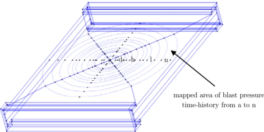
Since the Jones-Wilkins-Lee equation of state is incompatible with the compressible material models, the mapping method was incorporated to define the blast loading on the surface of concrete slab. Although the mapping method consumes much longer preparation time, it is capable of saving computational run time and yet produces accurate results. The surface of concrete slab was mapped
onto fifteen areas (area a until n) according the arrival time and the positive duration of blast
load-ing. Beyond the area n, only ambient pressure of 101kPa was considered. For a comparison, an
Latin American Journal of Solids and Structures 13 (2016) 1086-1106
0 0.05 0.1 0.15 0.2 0.25 0.3 0.35 0
50 100 150 200 250 300
Time, t (msec)
B
last P
re
ssu
re
, P
f (M
P
a
)
n m l k j i h g f e d c b a
Figure 5: Blast pressure time-history for various mapped areas.
Figure 6: Mapping area of blast on the surface of concrete slab.
5 RESULTS AND DISCUSSION
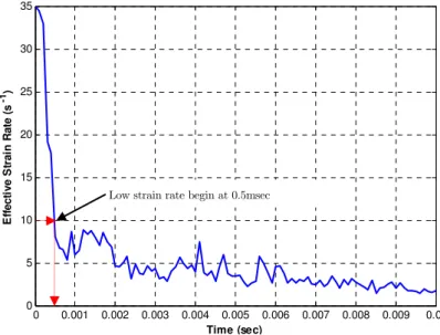
The numerical modeling using the combined finite-discrete element method allows comprehensive evaluations of the results in both continuum and fracture failures. When assessing the structure under high loading rates particularly blast loading, numerical results in term of scabbing, spalling and fracture behavior are of prime important. When an explosion occurs near to the surface of con-crete slab, the blast pressure or shock wave is first applied very locally at the point on the concon-crete slab closest to the explosive charge and then vary with the distances across the surface of concrete slab. As a result, the damage of concrete slab can be separated into local and overall responses which occur at different time periods (Duranovic and Watso, 1994). The transition phase of
effec-tive strain rate from high to low at 10s-1 can be used to distinguish these two forms of predominant
damage (Zhou et al., 2008). It is found from Figure 7 that the concrete slab started experiences low
a n d h l
Latin American Journal of Solids and Structures 13 (2016) 1086-1106
effective strain rate at time 0.5msec. This effective strain rate was evaluated based on the strain rate components varies with time that occurring during the crack formation and fracturing process at the center of beneath zone of concrete slab.
0 0.001 0.002 0.003 0.004 0.005 0.006 0.007 0.008 0.009 0.01
0 5 10 15 20 25 30 35
Time (sec)
Ef
fe
c
tiv
e
St
ra
in
R
a
te
(
s
-1)
Figure 7: Strain rate-time history.
5.1 Spalling and Scabbing
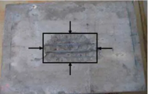
During the interaction of blast pressure on the concrete slab, which is happen approximately within 0.27msec at relatively high strain rate, the damage is localized as characterized by scabbing, spall-ing and shear plug. When the time reaches 0.5msec, the scabbspall-ing fully develops in a crater with
maximum depth of 50mm and damage area approximately 480´300mm2. Meanwhile, the spalling
at the top surface of concrete slab has damage area about 160´140mm2. The displacement of the
concrete slab is 8.82mm. A comparison between numerical and experimental results at time 0.5msec shows a favorable agreement and gives a reliable prediction on the scabbing and spalling as depicted in Figure 8. Further damage and progressive failure occur under the multi-reflected waves and con-tinuously exist due to the deformation owing by dynamic vibrations. This can be clearly observed by the fluctuation of low strain rate.
Spalling and scabbing damage are always formed during the duration of shock wave and reflect-ed wave. During the high strain rate stage, the scabbreflect-ed crater is formreflect-ed from the scabbing damage and the propagation of cracks along the steel reinforcement bars. The diameter of scabbed crater increases under the reflected wave and remains constant during the dynamic vibration. It is found that the dynamic vibration has a little effect on the scabbing damage. However, due to the combi-nation of reflected wave and dynamic vibration, approximately at time of 0.5msec to 0.75msec, cracks are propagate from the epicenter of concrete slab towards the free edges. Unlike scabbing damage which occurs soon after the concrete slab was loaded by blast pressure, spalling damage happens only during the transition of high to low strain rate. After that, the spalling damage prop-agates quickly but has no contribution to the fracture and fragmentation of the concrete slab. The
Latin American Journal of Solids and Structures 13 (2016) 1086-1106
diameter of the spalling and scabbing damage in the time history is shown in Figure 9. It can be clearly observed that the spalling and scabbing damage are almost constant under the dynamic vibration of more than 0.75msec.
a) Experiment: Spalling damage b) Experiment: Scabbing damage
a) Numerical: Spalling damage b) Numerical: Scabbing damage
Figure 8: Spalling and scabbing damage from experimental and numerical results.
0 0.001 0.002 0.003 0.004 0.005 0.006 0.007 0.008 0.009 0.010 100
150 200 250 300 350 400 450 500 550
Time, t (sec)
S
cab
b
ed
C
rat
er
, S
c an
d
S
p
al
li
n
g
, D
s (
m
m
)
Scabbed Crater, Sc Spalling, Ds
Latin American Journal of Solids and Structures 13 (2016) 1086-1106
Consider the initial of spalling damage and scabbed crater of 0.5kg explosive at 100mm and the scaling law established that any linear dimension of the crater can be expressed as a constant mul-tiplied by weight of the explosion (Ambrosini and Luccioni, 2012), simple formulas to evaluate the diameter of the spalling and scabbing damage can be written as:
1/3
0.45
c
S = W (13)
1/3
0.135
s
D = W (14)
where Sc is the apparent scabbed crater diameter in meter, Dsis the spalling damage diameter that
also in meter, and W is the equivalent TNT explosive weight in kilogram. Both equations have a
similar form of crater dimension defined by Kinney and Graham (1985) and Luccioni et al. (2009) in the prediction of damage and crater that caused by a spherical blast wave. However, these equa-tions are considered conservative as damage and crater behavior were defined in term of weight of explosive, whereas the damage behavior is highly likely to be influenced by the standoff distance and incidence angle in the form of scaled-distance function. However, when Equation (13) is plotted against the weight of explosion as shown in Figure 10, the results of scabbed crater diameter are in the middle of the maximum and minimum curves produced by Xu and Lu (2006). The experimental data from Yuan et al. (2008) has lower scabbed crater diameter at weight of explosion of 5kg, 8kg
and 10kg. This is probably because of the ratio of span to thickness (L/d) of the concrete slab used
in experimental study is smaller than 10. It should be noted here that the L/d of the concrete slab
in numerical modeling is 13.
0 1 2 3 4 5 6 7 8 9 10
0.2 0.3 0.4 0.5 0.6 0.7 0.8 0.9 1.0
Weight of Explosion, W (kg)
S
c
ab
b
e
d
C
rat
e
r Di
am
et
e
r,
S
b
(
m
)
Analysis Yuan et al. Xu & Lu (max) Xu & Lu (min)
Figure 10: Prediction of scabbed crater diameter of reinforced concrete slab.
5.2 Fracture Failure
Latin American Journal of Solids and Structures 13 (2016) 1086-1106
plug and fracture that happen during the explosion phase and the dynamic vibration at time in-stants ranging from 0.5msec to 5.0msec. Red color indicates the continuum body while blue color represents the fractured elements. The shear plug and fracture were observed along the mid-cross section of long span direction. At the time of 0.5msec during the transition from high to low strain rate, the initial region of potential fracturing is observed to be appeared at the mid-layer of the concrete slab and some fracture occurs at the beneath zone.
a) t=0.5 msec b) t = 1.0 msec
c) t = 2.0 msec d) t = 3.0 msec
e) t = 4.0 msec f) t = 5.0 msec
Figure 11: Shear plug and fracture formation at time 0.5 msec to 5.0 msec.
A shear plug in the pattern of a conical frustum is formed by incline cracking through the thickness of concrete slab. This phenomenon corresponds closely to the formation of shear plug in-vestigated by Yankelevsky (1994) on the concrete slab under low velocity impact. Then, fracture aggressively forms along the concrete thickness as new cracks are generated at the middle of span. It is found that the shear plug significantly contributes to the separation of elements and lead to the formation of scabbed fracture. In addition, fracture also happen due to the cracks of the bond-slip phenomenon between steel reinforcements and concrete. In this numerical modeling, there is no fracture that induces from spalling damage. However, Yongxiang et al. (2009) argued that a con-crete structure under contact explosion may experience serious spalled fracture.
Latin American Journal of Solids and Structures 13 (2016) 1086-1106
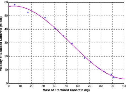
define a universally acceptable threshold since fracture depends on many factors and is subjective to the ability of elements to be separated. In this study, an effort to investigate the fragment weight of concrete slab was performed by assessing fracture together with scabbed damage. The grievance of this approach is that the fragment weight of concrete may unjustified and overestimated, but such approach is extremely valuable. Figure 12 displays the relation of the velocity with weight of fractured concrete. When the fracture ejected from the concrete slab, it is moving down with high velocity ap-proximately 58m/sec, similar as suggested by Cormie et al. (2009).
0 10 20 30 40 50 60 70 80 90 100
0 10 20 30 40 50 60
Mass of Fractured Concrete (kg)
V
e
lo
c
it
y
o
f S
c
a
b
b
e
d
C
o
n
c
re
te
(
m
/s
e
c
)
Figure 12: Mass and velocity of fractured concrete.
6 CONCLUSIONS
Latin American Journal of Solids and Structures 13 (2016) 1086-1106
amount of uncertainty and the conjecture unconfirmed. Although an attempt was made to deter-mine the weight of fractured concrete directly from the scabbed damage elements, the shortcoming of this approach is that the weight of fracture may be unjustified and overestimated. However, this approach is extremely valuable and the accuracy of results can be considered convincing.
References
Alonso, G.M., Cendon, D.A., Galvez, F., Erice, B. and Galvez, V.S. (2011). Blast response analysis of reinforced concrete slabs: experimental procedure and numerical simulation, Journal of Applied Mechanics 78(5): 510-522. Ambrosini, R.D. and Luccioni, B.M. (2012). Craters produced by explosions on, above and under the ground, Ad-vances in protective structures research, Taylor and Francis (London), 365-396.
Amir. S., van der Veen, C. and Walraven, J.C. (2014). Numerical investigation of the bearing capacity of transverse-ly prestressed concrete deck slabs, Computational modelling of concrete structures, Taylor and Francis (London), 99-108.
Bazant, Z.P. and Becq-Giraudon, E. (2002). Statistical prediction of fracture parameters of concrete and implications for choice of testing standard, Cement and Concrete Research 32(4): 529-556.
Bere, A.T. (2004). Computational modelling of large-scale reinforced concrete structures subjected to dynamic load-ing, Ph.D. Thesis, Swansea University, United Kingdom.
Bhattacharjee, S.S. and Leger, P. (1994). Application of NLFM models predict crcaking in concrete gravity dams, Journal of Structural Engineering 120(4): 1255-1271.
Bouamoul, A. and Dang, T.V.N. (2008). High explosive simulation using arbitrary lagrangian-eulerian formulation, Technical Report TM 2008-254, Defence Research and Development, Canada.
Brara, A., Camborde, F., Klepaczko, J.R. and Mariotti, C. (2001). Experimental and numerical study of concrete at high strain rates in tension, Mechanics of Materials 33(1): 33-45.
Cerveta, M. and Hinton, E. (1986). Computational modelling of reinforced concrete structures, Pineridge Press (Swansea).
Chafi, M.S., Karami, G. and Ziejewski, M. (2009). Numerical analysis of blast-induced wave propagation using FSI and ALE multi-material formulation, International Journal of Impact Engineering 36(10-11): 1269-1275.
Cormie, D., Mays, G. and Smiths, P. (2009). Blast effects on buildings, Thomas Telford (London).
Cottrell, M.G. (2002). The development of rational computational strategies for the numerical modelling of high velocity impact, Ph.D. Thesis, Swansea University, United Kingdom.
Cottrell, M.G., Yu, J., Wei, Z.J. and Owen, D.R.J. (2003). The numerical modelling of ceramics subjected to impact using adaptive discrete element technique, Engineering Computations 20(1): 82-106.
De Borst, R., Crisfield, M.A., Remmers, J.J.C. and Verhoosel, C.V. (2012). Non-linear finite element analysis of solids and sructures, John Wiley and Sons (West Sussex)
Deng, R.B. and Jin, X.L. (2009). Numerical simulation of bridge damage under blast loads. WSEAS Transaction in Computers 9(8): 1564-1574.
Dobartz, B.M. (1981). LLNL explosives handbook: properties of chemical explosives and explosive simulation, Uni-versity of California Press (California).
Duranovic, N. and Watso, A.J. (1994). Impulsive loading on reinforced concrete slabs-blast loading functions, Trans-action on the Built Environment 8: 63-73.
Latin American Journal of Solids and Structures 13 (2016) 1086-1106
Elsanadedy, H.M., Almusallam, T.H., Abbas, H., Al-Salloum, Y.A. and Alsayed, S.H. (2011). Effect of blast loading on cfrp-retrofitted rc columns-a numerical study, Latin American Journal of Solids and Structures 8(1): 55-81. Frangin, E., Marin, P. and Daudeville, L. (2006). On the use of combined finite/discrete element method for impact-ed concrete structures, Journal de Physique IV 134(1): 461-466.
Gronsten, G.A. and Forsen, R. (2007). Debris launch velocity from overloaded concrete cubicles, Proceeding of the International Symposium on Interaction of the Effects of Munitions with Structures, Orlando.
Guzina, B.B., Rizzi, E., Willam, K. and Pak, R.Y.S. (1995). Failure prediction of smeared-crack formulations, Jour-nal of Engineering Mechanics 121(1): 150-161.
Jaini, Z.M. and Feng, Y.T. (2011). Computational modelling of damage behaviour of reinforced concrete slabs sub-jected to blast loading, Proceeding of the 8th International Conference on Structural Dynamics, Leuven.
Kim, J.H.J., Yi, N.H., Oh, I.S., Lee, H.S., Choi, J.K. and Cho, Y.G. (2010). Blast loading response of ultra perfor-mance concrete and reactive powder concrete slabs, Fracture mechanics of concrete and concrete structures, Korean Concrete Institute ( Seoul), 1715-1722.
Kinney, G.F. and Graham, K.J. (1985). Explosive shocks in air, Springer-Verlag (New York).
Klerck, P.A., Sellers, E.J. and Owen, D.R.J. (2004). Discrete fracture in quasi-brittle materials under compression and tensile stress states, Computer Methods in Applied Mechanics and Engineering 193(27-29): 3035-3056.
Labuz, J.F. and Zang, A. (2012). Mohr-Columb failure criterion, Rock Mechanics and Rock Engineering 45(6): 975-979.
Lambert, D.E. and Allen, R.C. (2000). Strain rate effects on dynamic fracture and strength, International Journal of Impact Engineering 24(10): 985-998.
Luccioni, B.M. and Luege, M. (2006). Concrete pavement slab under blast loads, International Journal of Impact Engineering 32(8): 1248-1266.
Luccioni, B.M., Ambrosini, D., Yuen, S.C.K. and Nurick, G.N. (2009). Evaluating the effect of large and spread explosives loads, Argentina Association for Computational Mechanics 28: 529-552.
Malvar, L.J. and Crawford, J.E. (1998). Dynamic increase factors for steel reinforcing bars, Proceeding of the 28th DDESB Seminar, Orlando.
Malvar, L.J. and Ross, C.A. (1998). Review of strain rate effects for concrete in tension, ACI Materials Journal 95(6): 735-739.
May, I.M., Chen, Y., Owen, D.R.J., Feng, Y.T. and Thiele, P.J. (2006). Reinforced concrete beams under drop-weight impact loads, Computers and Concrete 3(2-3): 79-90.
Munjiza, A., Latham, J.P. and Adrews, K.R.F. (2000). Detonation gas model for combined finite-discrete element simulation of fracture and fragmentation, International Journal of Numerical Methods in Engineering 49(12): 1495-1520.
Ngo, T., Mendis, P., Gupta, A. and Ramsay, J. (2007). Blast loading and blast effects on structures: an overview, Electronic Journal of Structural Engineering Special Issue: 76-91.
Oh, B.H., Jang, S.Y. and Byun, H.K. (1999). Prediction of fracture energy of concrete, KCI Concrete Journal 11(3): 211-221.
Owen, D.R.J. and Feng Y.T. (2001). Parallelised finite/discrete simulation of multi-fracturing solids and discrete systems, Engineering Computations 18(3/4): 557-576.
Owen, D.R.J., Feng, Y.T., Cottrell, M.G. and Yu, J. (2007). Computational issues in the simulation of blast and impact problems: an industrial perspective, Springer (Netherlands), 3-35.
Latin American Journal of Solids and Structures 13 (2016) 1086-1106 Rabezuk, T. and Eibl, J. (2006). Modelling dynamic failure of concrete with meshfree methods, International Journal of Impact Engineering 32(11): 1878-1897.
Rao, G.A. and Prasad, B.K.R. (2002). Fracture energy and softening behavior of high-strength concrete, Cement and Concrete Research 32: 247-252.
Razaqpur, A.G., Tolba, A. and Contestabile, E. (2007). Blast loading response of reinforced concrete panels rein-forced with externally bonded gfrp laminates, Composites Part B 38: 535-546.
Rockfield Software Limited. (2009). Elfen explicit manual version 4.4: data file specification-material models, Rock-field Software Limited (Swansea).
Schenker, A., Anteby, I., Gal, E., Kivity, Y., Nizri, E., Sadot, O., Michaelis, R., Levintant, O. and Ben-Dor, G. (2008). Full-scale field tests of concrete slabs subjected to blast loads, International Journal of Impact Engineering 35: 184-198.
Schuler, H., Mayrhofer, C. and Thoma, K. (2006). Spall experiments for the measurement of the tensile strength and fracture energy of concrete at high strain rates, International Journal of Impact Engineering 32(10): 1635-50.
Seman, M.A., Nasly, M.A., Feng, Y.T. and Jaini, Z.M. (2013). Computational modelling of reinforced concrete wall subjected to transformer tank rupture, Research and applications in structural engineering, mechanics and computa-tion, Taylor and Francis (London), 195-196.
Silva, P. and Lu, B. (2009). Blast resistance of reinforced concrete slabs, Journal of Structural Engineering 135(6): 708-716.
Smoljanovic, H., Zicaljic, N. and Nikolic, Z. (2013). Nonlinear analysis of engineering structures by combined finite-discrete element method, Gradevinar 65(4): 331-344.
Souli, M., Ouahsine, A. and Lewin, L. (2000). ALE formulation for FSI problems, Computer Methods in Applied Mechanics and Engineering 190(5-7): 659-675.
Steadm, D., Coggan, J.S. Eberhardt, E. (2004). Realistic simulation of rock slope failure mechanisms: the need to incorporate principles of fracture mechanics, International Journal of Rock Mechanics and Mining Sciences 41(1): 563-568.
Timothy, P.P., Shah, M.Y. and Robert D.C. (1991). Solid elements with rotational degrees of freedom: part ii-tehrahedron elements, International Journal of Numerical Methods in Engineering 31(3): 593-610.
Ulfkjaer, J.P. and Brincker, R. (1995). Fracture energy of normal strength concrete, high strength concrete and ultra high strength ultra ductile steel fibre reinforced concrete, Aedificatio Publishers (Freiburg), 31-44.
Urgessa, G.S. (2009). Finite element analysis of composite hardened walls subjected to blast loads, Journal of Engi-neering and Applied Sciences 2(4): 804-811.
Vyazmensky, A., Elmo. D. and Stead, D. (2007). Combined finite-discrete element modelling of surface subsidence, Proceeding of the 1st Rock Mechanics Symposium, Vancouver.
Wang, M., Hao, H, Ding, Y. and Li, Z.X. (2009). Prediction of fragment size and ejection distance of masonry wall under blast loading using homogenized masonry material properties, International Journal of Impact Engineering 36(6): 808-820.
Wu, C., Nurwidayati, R. and Oehlers, D.J. (2009). Fragmentation from spallation of rc slabs due to airblast loads, International Journal of Impact Engineering 36(12): 1371-1376.
Xu, K. and Lu, Y. (2006). Numerical simulation study of spallation in reinforced concrete plates subjected to blast loading, Computer and Structure 84(5-6): 431-438.
Yankelevsky, D.Z. (1994). Local response of concrete slab to low velocity missile impact, International Journal of Impact Engineering 19(4): 331-343.
Latin American Journal of Solids and Structures 13 (2016) 1086-1106
Yu. J. (1999). Contact interaction framework for numerical simulation of multi-body problems and aspects of dam-age and fracture for brittle material, Ph.D. Thesis, Swansea University, United Kingdom.
Yuan, L., Gong, S. and Jin, W. (2008). Spallation mechancism of rc slabs under contact detonation, Transaction Tianjin University 14(6): 464-469.