www.mech-sci.net/6/57/2015/ doi:10.5194/ms-6-57-2015
© Author(s) 2015. CC Attribution 3.0 License.
Kinematic analysis of a novel 3-CRU translational parallel
mechanism
B. Li1,2, Y. M. Li1,2, X. H. Zhao2, and W. M. Ge2
1Faculty of Science and Technology, University of Macau, Taipa, Macau, China
2Tianjin Key Laboratory for Advanced Mechatronic System Design and Intelligent Control, Tianjin University
of Technology, Tianjin, China
Correspondence to:Y. M. Li ([email protected])
Received: 25 November 2014 – Revised: 1 April 2015 – Accepted: 12 April 2015 – Published: 24 April 2015
Abstract. In this paper, a modified 3-DOF (degrees of freedom) translational parallel mechanism (TPM) three-CRU (C, R, and U represent the cylindrical, revolute, and universal joints, respectively) structure is proposed. The architecture of the TPM is comprised of a moving platform attached to a base through three CRU jointed serial linkages. The prismatic motions of the cylindrical joints are considered to be actively actuated. Kinematics and performance of the TPM are studied systematically. Firstly, the structural characteristics of the mechanism are described, and then some comparisons are made with the existing 3-CRU parallel mechanisms. Although these two 3-CRU parallel mechanisms are both composed of the same CRU limbs, the types of freedoms are completely different due to the different arrangements of limbs. The DOFs of this TPM are analyzed by means of screw theory. Secondly, both the inverse and forward displacements are derived in closed form, and then these two problems are calculated directly in explicit form. Thereafter, the Jacobian matrix of the mechanism is de-rived, the performances of the mechanism are evaluated based on the conditioning index, and the performance of a 3-CRU TPM changing with the actuator layout angle is investigated. Thirdly, the workspace of the mecha-nism is obtained based on the forward position analysis, and the reachable workspace volume is derived when the actuator layout angle is changed. Finally, some conclusions are given and the potential applications of the mechanism are pointed out.
1 Introduction
In recent years, lower-mobility translational parallel mecha-nisms (TPMs) have been extensively studied. Compared with 6-DOF (degrees of freedom) parallel manipulators, lower-mobility mechanisms possess many merits in terms of sim-pler mechanical design, larger workspace, and lower manu-facturing cost, in addition to the inherent advantages of the general parallel manipulators, such as high accuracy, high stiffness, high velocity, high dynamic performance, large load-to-weight ratio, low moving inertia, and little accumula-tion of posiaccumula-tional errors. A lower-mobility TPM with 3 DOFs is a focus of the current trend in the research community, and various forms of 3-DOF TPMs have been designed. A 3-DOF TPM is a 3-DOF parallel mechanism whose moving platform can achieve three independent orthogonal transla-tional motions with respect to its fixed base.
Cylindrical joint
Supporting rail
Fixed base Moving platform
Universal joint
Revolute joint
Figure 1.The existing 3-CRU spherical wrist.
in terms of higher compactness and stiffness and no singular-ities in the workspace. Lou and Li (2006) proposed a novel 3-DOF purely TPM, named Orthotripod. The mechanism pos-sessed a nearly ball-shaped workspace, and had a much better conditioning index than that of the tripod-based mechanism. The CICABOT was presented in Ruiz et al. (2012), which was a novel 3-DOF TPM based on two five-bar mechanisms. The workspace of the CICABOT was large and its workspace volume was limited by the size of the links, and both the in-verse and direct kinematics were very simple to determine. The dynamics modeling of a translational 3-CPU was inves-tigated via screw theory (Carbonari et al., 2013). The oper-ation performance of a LARM leg mechanism with 3-UPU parallel architecture was studied in Wang et al. (2015). Be-sides these new 3-DOF TPMs mentioned above, some other 3-DOF architectures can be found in the literature (Li and Xu, 2006; Simoni et al., 2013; Gregorio and Parenti-Castelli, 2002; Ji and Wu, 2003; Chung and Hervé, 2006; Kim and Chung, 2003; Merlet, 2006; Li and Xu, 2005a, b; Tsai and Joshi, 2002; Chablat and Wenger, 2001).
In this paper, a modified 3-DOF TPM (3-CRU, where the letters C, R, and U represent the cylindrical, revolute, and universal joints, respectively) is proposed. The structure of the paper is arranged as follows. In Sect. 2, the proposed mechanism is compared with other existing mechanisms. The mobility of the mechanism is analyzed by means of screw theory in Sect. 3. In Sect. 4, an analytical model for the kinematics of the mechanism is established, and the ex-act analytical solutions are found both for the inverse and forward kinematics problems. In Sect. 5, the Jacobian matrix of the mechanism is derived. The reachable workspace of the mechanism is obtained based on the forward position anal-ysis in Sect. 6. Conclusions and areas of future research are given in Sect. 7.
Cylindrical joint
Supporting rail Fixed base
Moving platform
Universal joint
Revolute joint
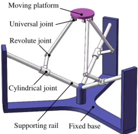
Figure 2.The modified 3-CRU TPM.
2 A modified 3-CRU TPM and its structural characteristics
With regard to previous works, a 3-CRU rotational parallel manipulator, as shown in Fig. 1, was first introduced in Fang and Tsai (2004); subsequent to this, the kinematics, dynamics and kineto-elasto-static synthesis of a 3-CRU spherical wrist were studied by Callegari et al. (2007a, b).
In this paper, a modified structure of 3-CRU TPM, shown in Fig. 2, is proposed. The orientational mechanism (Fig. 1) and the positional mechanism (Fig. 2) differ from each other in the axes of the revolute joints and universal joints. The dif-ferent joint arrangements of CRU limbs in these two types of 3-CRU parallel mechanisms are demonstrated in Fig. 3. The 3-CRU TPM consists of a base platform, a moving platform, three supporting rails, and three limbs with identical kine-matic structures. Each limb connects the fixed base to the moving platform via a cylindrical joint, a revolute joint, and a universal joint in sequence. The cylindrical joint, actuated by a linear actuator, can move along the supporting rail and rotate on the rail simultaneously (Fig. 4), and the rails are symmetrically arranged 120◦ apart. Thus, the moving plat-form is attached to the base by three identical CRU linkages. For the sake of analysis, a fixed Cartesian reference coor-dinate frameO-xyzis attached at the centered pointO of the intersection point of three supporting rails as shown in Fig. 5.Ai is the center of the cylindrical joint,Bi is the
cen-ter of the revolute joint,Ci is the center of the universal joint,
and pointP is the center of the moving platform. Angleαiis
measured from the base platform to railsOAi and is defined
as the actuator layout angle. In order to ensure the isotropic property of the mechanism, we assumeα1=α2=α3=α.
3 Mobility analysis via screw theory
(a) (b)
Cylindrical joint Revolute joint
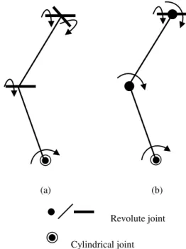
Figure 3.Different joint arrangement of a CRU limb.(a)Joint ar-rangement of the CRU limb of an existing 3-CRU spherical wrist.
(b)Joint arrangement of a CRU limb of a modified 3-CRU TPM.
Stator Slider Revolute joint
Figure 4.A CAD model of a cylindrical joint.
are translational or rotational DOF), screw theory is em-ployed to analyze the mobility of a 3-CRU parallel manip-ulator, which is a convenient tool for studying instantaneous motion systems that include both rotational and translational motions in three-dimensional space.
The mobility of the 3-CRU TPM is determined by the combined effect of the three limb constraint forces/couples. Here, the reciprocal screw theory is used to analyze con-straint forces exerted on the moving platform in order to give a complete description of how the mobility of TPMs is com-puted (Dai et al., 2006). Without losing generality, a local coordinate system Ai−xiyizi,(i=1–3) is established for
each limb and twist system of theith CRU limb as shown in
x
y
z
r
i iC qs
i
A
iB
i
C
O
iR
s
limb 1 limb 2
limb 3
P
Figure 5.Schematic model of the mechanism.
Supporting rail
Revolute joint Cylindrical joint
Universal joint
i
A
i
x
i
y
i
z
ic
s
iR
s
1 iUs
2iU
s
i
B
i C
Figure 6.Twist systems of a CRU limb.
Fig. 6:
$1=(0 siC) $2=(siC 0) $3=(siR riR×siR)
$4=(siU1 riU×siU1) $5=(siU2 riU×siU2),
(1)
wheresiCandsiRstand for the unit direction vector of cylin-drical and revolute joints, respectively, and siC=siR. siU1 andsiU2are the unit direction vectors of universal joints.
Using the reciprocity between twist and wrench, the CRU limb constraint system can be calculated by
$r1=(0 ni), (2)
x
(
mm
)
y
(
mm
)
z
(
mm
)
O
A
iB
iC
iB
i’Figure 7.Different configurations for inverse position.
In Eq. (2), three CRU limbs provide three constraint cou-ples restricting rotational DOFs around the axis of the con-straint couples. Therefore the moving platform of the 3-CRU TPM behaves as if it has only three translational DOFs.
4 Inverse and forward position analyses
4.1 Inverse position analysis
Inverse position analysis of the 3-CRU TPM involves the de-termination of the position of Ai given the position of the
moving platform.
In theO-xyzframe, the position vectorr=(xyz)T of
po-sitionP can be expressed as
r=qisiC+AiBi+BiCi−P Ci, (i=1,2,3), (3)
whereqi = kOAikstands for the position ofAi,siC is the unit vector ofOAi,AiBi is the vector from pointAito point
Bi,BiCi is the vector from pointBito pointCi, andP Ci is
the vector from pointP to pointCi.
Note that, for the CRU limb, the constraint imposed by the revolute joint restricts bothAiBi andBiCi so that they are
normal to the unit vectorsiRof the revolute joint axis. Thus, taking the dot product withsiRon both sides of Eq. (3) leads to
qi= r+P Ci T
siR, (i=1,2,3). (4)
Thus, for a given position vectorr=(x y z)T of the moving platform, the position of Ai can be obtained directly using
Eq. (4).
4.2 Forward position analysis
Forward position analysis of the mechanism is concerned with the determination of the moving platform position given the position ofAi.
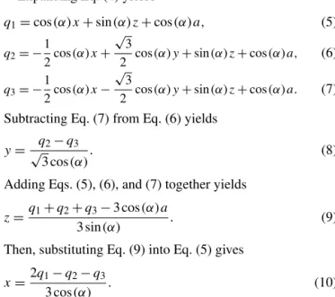
Expanding Eq. (4) yields
q1=cos (α)x+sin (α)z+cos (α)a, (5)
q2= − 1
2cos (α)x+ √
3
2 cos (α)y+sin (α)z+cos (α)a, (6)
q3= − 1
2cos (α)x− √
3
2 cos (α)y+sin (α)z+cos (α)a. (7)
Subtracting Eq. (7) from Eq. (6) yields
y=√q2−q3
3 cos (α). (8)
Adding Eqs. (5), (6), and (7) together yields
z=q1+q2+q3−3 cos (α)a
3 sin (α) . (9)
Then, substituting Eq. (9) into Eq. (5) gives
x=2q1−q2−q3
3 cos (α) . (10)
Lastly, given a set of (q1 q2 q3),x,y, andzcan be solved by using Eqs. (8), (9), and (10).
It should be pointed out that the actuator layout angle should be set in the range of 0–90◦ to ensure that the robot
has real solutions for the forward position analysis.
For the proposed 3-CRU TPM in this paper, both the inverse and the forward position analyses of the mecha-nism can be calculated directly in explicit form as shown in Sects. 4.1 and 4.2, which is extremely significant for the pos-sible practical applications of the mechanism.
4.3 Numerical examples
The architectural parameters of a 3-CRU TPM are selected as a=100 mm, l1=300 mm, l2=500 mm, and α=30◦; here, a= kP Cik, l1= kAiBik, and l2= kBiCik. For the
inverse position analysis, given a set of inputs (x y z), out-put parameters can be calculated as shown in Table 1, and Fig. 7 depicts the configurations associated with these solu-tions. For the forward position analysis, given a set of inputs (q1 q2 q3), output parameters can be calculated as shown in Table 2, and the configurations associated with these solu-tions are described in Fig. 8.
For a given position vectorr=(x y z)T of the moving
platform, only one solution of theAi positions can be
ob-tained using Eq. (4) directly, as shown in Fig. 7. However, the locations of pointBi have two possibilities for a CRU limb,
Table 1.Inverse position analysis of the mechanism (unit: mm).
Inputs Outputs
x y z q1 q2 q3
Case (a) 80 −50 600 455.8846 314.4615 389.4615
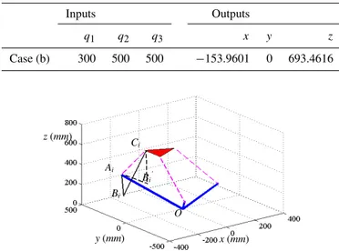
Table 2.Forward position analysis of the mechanism (unit: mm).
Inputs Outputs
q1 q2 q3 x y z
Case (b) 300 500 500 −153.9601 0 693.4616
x (mm)
y (mm)
z (mm)
O Ai
Bi
Ci
Bi’
Figure 8.Different configurations for forward position analysis.
5 Jacobian matrix of the mechanism and performance analysis
5.1 Jacobian matrix of the mechanism
Differentiating Eqs. (5), (6), and (7) with respect to time re-spectively yields
˙
q1=cos (α)x˙+sin (α)z,˙ (11)
˙ q2= −
1
2cos (α)x˙+ √
3
2 cos (α)y˙+sin (α)z,˙ (12)
˙ q3= −1
2cos (α)x˙− √
3
2 cos (α)y˙+sin (α)z.˙ (13)
Equations (11), (12), and (13) can be written in matrix form. Only when the manipulator is away from singularities is the matrix invertible.
˙
q=JX˙, (14)
where q˙=
˙
q1 q˙2 q˙3T,q˙i is the velocity of the ith
lin-ear actuator, and X˙ = x˙ y˙ z˙T represents the three-dimensional linear velocity of the moving platform.
J=
cos (α) −12cos (α) −12cos (α)
0
√
3 2 cos (α) −
√
3 2 cos (α)
sin (α) sin (α)
sin (α)
is the Jacobian matrix of the mechanism.
Configuration 1 Configuration 2
A
iC
iB
iB
i’
Figure 9.Two possible configurations of a CRU limb.
WhenJis invertible, Eq. (14) can be written as
˙
X=J−1q˙. (15)
Equation (15) represents the forward velocity solution for a 3-CRU TPM.
5.2 Performance analysis
With respect to performance evaluation and optimization, the most used parameter is the Jacobian matrix, which is the ma-trix map of the velocity of the end effector onto the vector of actuated joint velocities. The conditional number of the Jaco-bian matrix, called the local conditioning index (LCI) (Li et al., 2005), was applied for performance evaluation of parallel manipulators. The conditioning index can be defined as the ratio of the smallestλminto the largestλmaxsingular values ofJ, i.e.,
κ=λmin λmax
. (16)
( )
Figure 10.Relationship between the performance and the actuator layout angle.
mechanism are set up in the same way as those in Sect. 4.3. Then, the relationship between the performance of the mech-anism and the actuator layout angleαis obtained as shown in Fig. 10, and the actuator layout angle should be given in the range 25–45◦to ensure good kinematic performance of the manipulator.
6 Workspace analysis
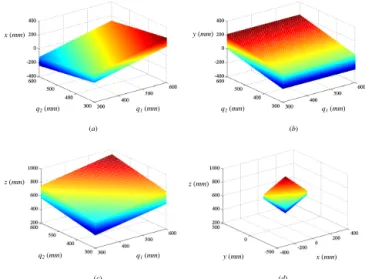
In this section, the reachable workspace of the 3-CRU TPM is obtained based on the forward position analysis. Given a set of limb lengths (q1 q2 q3), the position of the moving platform can be calculated directly by corresponding equa-tions as shown in Section 4. Thus when the restricequa-tions to the limb lengths are set up, the reachable workspace of the mech-anism can be obtained. It should be mentioned that few TPMs can obtain the workspace through forward position analysis; this is also one novel contribution in this paper.
Compared with serial ones, parallel manipulators have a relatively small workspace. The characteristics change with the variation in the actuator layout angle in the reachable workspace of a 3-CRU TPM..
The restrictions to the limb lengths are defined as 300 mm≤q1≤600 mm, 300 mm≤q2≤600 mm, and 300 mm≤q3≤600 mm. The workspace of the manipulator can be generated by a MATLAB program, the results of which are shown in Fig. 11.
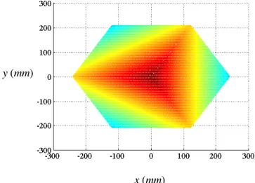
In order to investigate the reachable workspace volume of a 3-CRU TPM with the changing of the actuator layout angle, the workspace volume is illustrated in Fig. 12, from which it can be observed that the maximum workspace volume occurs when the actuator layout angle α is around 35◦. The x–y
section of the workspace forα=35◦is shown in Fig. 13.
(d) x (mm) y (mm)
z (mm)
(c)
q2 (mm) q1 (mm)
z (mm)
q1 (mm)
q2 (mm)
y (mm)
(b) q1 (mm)
q2 (mm)
x (mm)
(a)
Figure 11.The workspace of the manipulator.
Actuator layout angle deg.
Figure 12.Reachable workspace volume versus actuator layout an-gle.
7 Conclusions
y (mm)
x (mm)
Figure 13.x–ysection of the workspace atα=35◦.
reachable workspace is obtained based on the forward po-sition analysis, and the reachable workspace volume is ob-tained when the actuator layout angle is varied. On the ba-sis of the kinematics analyba-sis of the mechanism, analyses of inverse/forward dynamics and stiffness performance as well as kinematic optimization of the mechanism will be investi-gated in future work.
Acknowledgements. This work was supported by the National Natural Science Foundation of China (51205289, 51275353), the Natural Science Foundation of Tianjin (14JCZDJC39100), the Macao Science and Technology Development Fund (108/2012/A3, 110/2013/A3), and the Research Committee of University of Macau (MYRG183(Y1-L3)FST11-LYM, MYRG203(Y1-L4)-FST11-LYM).
Edited by: J. Schmiedeler
Reviewed by: two anonymous referees
References
Callegari, M., Cammarata, A., Gabrielli, A., and Sinatra, R.: Kine-matics and dynamics of a 3-CRU spherical parallel robot, in: Pro-ceedings of the ASME International Design Engineering Techni-cal Conferences & Computers and Information in Engineering Conference, Las Vegas, Nevada, USA, 91–101, 2007.
Callegari, M., Cammarata, A., and Ruggiu, M.: Kinetostatic synthe-sis of a 3-CRU spherical wrist for miniaturized assembly tasks, Proc. 18th AIMeTA Congress of Theoretical and Applied Me-chanics, Brescia, Italy, 10–26, 2007.
Carbonari, L., Battistelli, M., Callegari, M., and Palpacelli, M.-C.: Dynamic modelling of a 3-CPU parallel robot via screw theory, Mech. Sci., 4, 185–197, doi:10.5194/ms-4-185-2013, 2013. Chablat, D. and Wenger, P.: Architecture optimization of a 3-DOF
translational parallel mechanism for machining applications, the Orthoglide, IEEE Trans. Robot. Auto., 255, 1–8, 2001.
Chung, C. L. and Hervé, J. M.: Translational parallel manipulators with doubly planar limbs, Mech. Mach. Theory, 41, 433–455, 2006.
Clavel, R.: Delta, A fast robot with parallel geometry, in: Proceed-ings of 18th International Symposium on Industrial Robots, Lau-sanne, France, 91–100, 1988.
Dai, J. S., Huang, Z., and Lipkin, H.: Mobility of overconstrained parallel mechanisms, ASME J. Mech. Des., 128, 220–222, 2006. Di Gregorio, R.: Kinematics of the translational 3-URC mechanism,
ASME J. Mech. Des., 126, 1113–1117, 2004.
Di Gregorio, R. and Parenti-Castelli, V.: Mobility analysis of the 3-UPU parallel mechanism assembled for a pure translational mo-tion, ASME J. Mech. Des., 124, 259–264, 2002.
Fang, Y. F. and Tsai, L. W.: Analytical identification of limb struc-tures for translational parallel manipulators, J. Robot. Syst., 21, 209–218, 2004.
Ji, P. and Wu, H. T.: Kinematics analysis of an offset 3-UPU transla-tional parallel robotic manipulator, Robot. Auton. Syst., 42, 117– 123, 2003.
Kim, D. and Chung, W. K.: Kinematic condition analysis of three-DOF pure translational parallel manipulators, ASME J. Mech. Des., 125, 323–331, 2003.
Li, W., Gao, F., and Zhang, J.: R–CUBE, A decoupled parallel ma-nipulator only with revolute joints, Mechan. Mach. Theory, 41, 433–455, 2006.
Li, Y. M. and Xu, Q. S.: Kinematic analysis and design of a new 3-DOF translational parallel manipulator, ASME J. Mech. Des., 128, 729–737, 2006.
Li, Y. M. and Xu, Q. S.: Design and Analysis of a New 3-DOF Com-pliant Parallel Positioning Platform for Nanomanipulation, in: Proceedings of 5th IEEE Conference on Nanotechnology, 126– 129, 2005.
Li, Y. M. and Xu, Q. S., Kinematics and dexterity analysis for a novel 3-DOF translational parallel manipulator, in: Proceedings of IEEE International Conference on Robotics and Automation, 2955–2960, 2005.
Liu, X. J., Jeong, J., and Kim, J.: A three translational DOFs parallel cube-manipulator, Robotica, 21, 645–653, 2003.
Lou, Y. J. and Li, Z. X.: A novel 3-DOF purely translational par-allel mechanism, in: Proceedings of the IEEE/RSJ, International Conference on Intelligent Robots and Systems, Beijing, China, 2144–2149, 2006.
Martins, D. and Carboni, A. P., Variety and connectivity in kine-matic chains, Mech. Mach. Theory, 43, 1236–1252, 2008. Merlet, J.-P.: Jacobian, manipulability, condition number, and
ac-curacy of parallel robots, ASME J. Mech. Des., 128, 199–206, 2006.
Ruiz-Torres, M. F., Castillo-Castaneda, E., and Briones-Leon, J. A.: Design and analysis of CICABOT: a novel translational parallel manipulator based on two 5-bar mechanisms, Robotica, 30, 449– 456, 2012.
Simoni, R., Doria, C. M., and Martins, D.:, Symmetry and invariants of kinematic chains and parallel manipulators, Robotica, 31, 61– 70, 2013.
Tsai, L. W. and Joshi, S.: Kinematics analysis of 3-DOF position mechanisms for use in hybrid kinematic machines, ASME J. Mech. Des., 124, 245–253, 2002.
Wang, M. F., Ceccarelli, M., and Carbone, G.: Experimental tests on operation performance of a LARM leg mechanism with 3-DOF parallel architecture, Mech. Sci., 6, 1–8, doi:10.5194/ms-6-1-2015, 2015.
Xiao, S. L., Li, Y. M., and Meng, Q. L.: Mobility analysis of a 3-PUU flexure-based manipulator based on screw theory and com-pliance matrix method, Int. J. Precision Eng. Manuf., 14, 1345– 1353, 2013.