Abstract—An upcoming trend that can be observed in vibratory finishing process is the use of fixtures. Fixturing increases the force flow of media onto component surfaces thereby contributing to an increased finishing action. Two sets of experiments were carried out on Ti-6Al-4V workpieces – non fixtured and fixtured vibratory finishing on a trough. The average surface roughness was measured and the results were juxtaposed. Fixtured vibratory finishing was found to have the same trend as the conventional vibratory finishing process. Fixturing conferred a significant advantage to vibratory finishing – saturation roughness was obtained relatively faster and thus reduced cycle times.
Index Terms—Average surface roughness, fixturing, Hashimoto’s rules, vibratory finishing
I. INTRODUCTION
ixtured vibratory finishing is being increasingly implemented in production lines across various industries. The reasons cited for increased utilization of fixturing include shorter cycle times, better-quality surface finishes, greater media-component interactions and also prevention of damage to the lining of the vibratory finishing equipment from parts with sharp edges [1]. For high value components such as fan blades and turbine blades, immobilization prevents them from colliding with each other. On the academic front, few scientific studies [2-5] have explored fixturing thus making it an upcoming area of research.
In this relatively new realm of vibratory finishing, the component is held by suitable means and immersed into the media container. This type of fixtured vibratory finishing is
also referred to as ‘Vibrostrengthening’ – a termed coined by Sangid et al. to describe the vibratory finishing process being used for shot peening to impart beneficial compressive stresses [2]. The fixtures can be classified into two types: static (fixed on the vibratory machine setup) or dynamic
Manuscript received February 29, 2016. This work was conducted within the Rolls-Royce@NTU Corporate Lab with support from the National Research Foundation (NRF) Singapore under the Corp Lab@University Scheme.
K. Ahluwalia is a Research Assistant with Rolls-Royce@NTU Corporate Lab c/o School of Mechanical and Aerospace Engineering, Nanyang Technological University, 50 Nanyang Avenue, Singapore 639798 (email: [email protected])
R. Mediratta is a Research Assistant with Rolls-Royce@NTU Corporate Lab c/o School of Mechanical and Aerospace Engineering, Nanyang Technological University, 50 Nanyang Avenue, Singapore 639798 (contact number: +65 83023361, email: [email protected])
S.H. Yeo is an Associate Professor with School of Mechanical and Aerospace Engineering, Nanyang Technological University, 50 Nanyang Avenue, Singapore 639798 (email: [email protected])
(freely floating in the media). Both the configurations are known to accelerate the finishing process producing desired average surface roughness (Ra) values in reduced cycle times. Due to fixturing, there is an increase in the relative velocities between the media and the component compared to a component in a conventional process [2, 5]. This leads to increased normal media impacts and higher force flow over the component [6, 7]. Mechanical fixturing, electromagnetic fixturing, magnetic fixturing and vacuum fixturing are some of the commonly used means of attaching components during a finishing operation [8, 9].
Considering the advantages of fixturing, mass finishing methods have been devised which are based on the concept of fixturing. Spindle finishing, drag finishing and stream finishing are some of these methods which are known to reduce cycle times by almost 33 % as compared to conventional vibratory finishing [10].
Hashimoto [11] carried out revolutionary research on model development and establishment of ground rules for vibratory finishing. He conducted numerous experimental runs to understand the characteristics of the process. Two bowl shaped tumbling machines with working capacities of 0.4 m3 and 1.0 m3 were used with various media. The machine frequency and amplitude were set to 21 Hz and 5 mm respectively for all the experiments. Carburized steel cylinders with hardness of 62 HRC and diameters ranging from 6 mm to 20 mm were used. Based on the observations and experimental analyses, the basic rules of vibratory finishing were summarized as below:
Rule 1: The surface of the components that are finished by the vibratory finishing process has an inherent surface
texture that has a constant roughness named “roughness limitation”. This rule was determined based on SEM and Ra analysis of the finished coupons. The microstructure remained consistent from 45 minutes and 180 minutes as shown in progressive SEM images in figure 1. The Ra value of the workpiece remained constant at 0.06 µm from 60 minutes till 180 minutes as shown in figure 2. Hashimoto proposed that this roughness limitation was dependent upon the key process variables of the vibratory finishing process: equipment type, media, compound, component material, frequency and amplitude of the machine.
Rule 2: As the difference between initial roughness of component to be finished and its roughness limitation becomes higher, the rate of roughness change becomes more rapid. This rule was established based on observations from the plots of Ra versus time as shown in figure 2. The graphs showed an exponential trend till their roughness limitation values and the components with higher Ra values showed a
Experimental Investigation of Fixtured
Vibratory Finishing
K. Ahluwalia, R. Mediratta, and S.H. Yeo
steeper drop to their saturation values.
Fig. 1. Progressive SEM images of vibratory finished workpieces from 0 minutes till 180 minutes [12]
Fig. 2. Ra-t plots for varying initial roughness values [12]
Sangid et al. [2, 3] carried out two studies in the field of vibrostrengthening – one on experimental investigation of fixturing the components and the second one on the fixtured process’ visualization and modeling. The studies were analyzed from a shot peening perspective and no observations were made pertaining to surface finish enhancement. Uhlmann et al. [4, 5] investigated and developed a geometry based model with DEM analysis for the transient phase of vibratory finishing. Their analysis involved Rz – t plots for robot guided drag finishing as shown in figure 3. Although drag finishing is an advanced form of fixtured finishing, a fundamental difference between this process and fixtured vibratory finishing is that the media container is not vibrating in drag finishing.
To the knowledge of the authors, no scientific studies have been conducted comparing fixtured components to non-fixtured ones with respect to change in Ra values. The present study will:
1) Contrast fixtured and non-fixtured modes of vibratory finishing
2) Examine whether the established principles for vibratory finishing proposed by Hashimoto hold true for this embodiment of the conventional process
3) Demonstrate how fixtured vibratory finishing can finish the components in a more effective manner
Fig. 3. Rz - t plots for robot guided drag finishing [4]
II. EXPERIMENTALSETUP
The equipment used for the trials was a vibratory finishing trough with an operating frequency and amplitude of vibrations of 25 Hz and 3.5 mm respectively. Super polishing media was loaded into it and an aqueous alkaline compound was used as a lubricant. The titanium (Ti-6Al-4V, Grade 5) glass peened workpieces used for experiments had dimensions of 50 x 50 x 10 mm3. These titanium coupons were divided into two halves –one with Ra values in the range of 0.9 – 1.2 µm (referred to smoother side hereafter) and the other with 2-2.3 µm (referred to rougher side hereafter) as shown in figure 4. Two sets of experiments were carried out:
1) Workpieces were thrown into the bulk of media flow without fixturing
2) Workpieces were secured to the workpiece holder which was immersed into the center of the trough containing media as shown in figure 5
Fig. 4. Titanium workpiece schematic with rougher and smoother sides
50 mm
50 mm
Ra = 2– 2.3 µm (rougher side)
Fig. 5. Experimental set up for fixtured vibratory finishing
Trials were run for 150 minutes for both sets of experiments with Ra readings being taken at 15 minutes
interval with the help of a Mitutoyo SJ-210 surface profilometer. Five readings for Ra measurements were taken
for both the halves of the workpiece. The cut-off wavelength used was 0.8 mm and 5 sampling lengths were measured with a stylus speed of 0.5 mm/s. The profilometer was calibrated after every 150 minutes using a reference specimen of roughness 2.94 µm ± 10%.
III. RESULTSANDDISCUSSIONS
The average of the 5 Ra readings per half of the sample along with their standard deviation error bars were plotted for 2 non-fixtured and 4 fixtured workpieces. Workpieces 1 and 2 correspond to the first set of experiments as mentioned in section 3 whereas workpieces 3-6 were carried out in accordance to the second set. The authors of this paper made the following observations:
1) The Ra– t plots for fixtured workpieces follow a distinct trajectory compared to freely floating ones. The only commonality is that both modes show a decreasing exponential trend in their surface roughness values with time. This is shown using exponential trend lines and their corresponding R2 values in figures 6 and 7. The rates at which the Ra values drop are significantly higher for fixtured workpieces. The non-fixtured workpieces do not reach saturation even after 150 minutes of runtime as compared to the fixtured workpieces. This is evident for both the rougher and smoother sides of the workpiece. Standard deviation was calculated for every measurement at 15 minute intervals. After 150 minutes, the combined standard deviation was calculated for each individual experimental run and the values are shown in table 1. On observation of the error bars for each of the plots and the values shown in table 1, it can be seen that the non-fixtured workpieces show higher variability in their Ra values as compared to their fixtured counterparts.
Fig. 6. Ra-t plots for rougher side of workpieces
Fig. 7. Ra-t plots for smoother side of workpieces
Work holder
Vibratory trough
Motor
Air spring insulators Stand
Media
TABLEI
COMBINED STANDARD DEVIATION VALUES FOR THE WORKPIECES
2) The Ra values of the fixtured workpieces 3-6 remained constant at around 0.1 µm. This Ra value which remains constant after a certain period of run time is referred to
as saturation roughness or “roughness limitation” as
observed by Hashimoto in his 1st rule [11]. On the other hand, the non-fixtured workpieces show a decreasing trend and do not appear to have reached their roughness limitation. The final surface finish depends on many process variables. Workpieces 1 and 2 may not have
reached saturation values like Hashimoto’s workpieces
did due to various differences in the parameters used then and now: machine configurations, media, geometry and material of workpiece. The freely floating workpieces did not experience substantial media interactions in 150 minutes. The authors of this manuscript opine that this may have been the prime reason why the inherent roughness limitation was not surfaced for the first set of experiments. Using the equations for the trend lines, the time taken to reach 0.1 µm was calculated for the non-fixtured workpieces. The values were 614 minutes and 308 minutes for workpiece 1 rougher and smoother sides respectively; and 635 minutes and 304 minutes for workpiece 2 rougher and smoother sides respectively. As can be seen, the Ra plots will cross their saturation roughness at a time well beyond the cycle time used in these set of experiments. 3) The workpieces were divided into two halves with
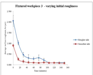
varying roughness values to examine whether the initial roughness makes a difference in the performance of the process. As observed in point 2 above, the Ra values of all the fixtured workpieces, irrespective of the starting Ra values saturate at 0.1 µm around the same time, t=105 minutes. Sample plots for workpieces 3 and 4, which were fixtured are shown in figures 8 and 9. It is evident that for the rougher side of the workpiece, the rate at which the Ra values drop is much faster than the smoother side of the same workpiece. Hence, it can be
concluded that for fixtured vibratory finishing,
Hashimoto’s 2nd rule holds valid: as the difference between initial roughness and roughness limitation increases, the rate at which the Ra values drop to the saturation values becomes faster.
Fig. 8. Effect of varying initial roughness - workpiece 3
Fig. 9. Effect of varying initial roughness - workpiece 4
4) Fixtured workpieces reach saturation faster than non-fixtured workpieces which can be attributed to the increased uniform force flow of media against the workpiece [2, 6, 7] , thereby increasing the efficiency of the process. The higher variability in a freely floating workpiece can be attributed to the random nature of media impacts on a freely floating workpiece. The surface is more uniformly finished for the fixtured workpieces as those are more stable in the bulk media flow. Fixturing can therefore be used to improve cycle times of the vibratory finishing process and have a consistent finish on the desired component.
Workpiece
number Fixturing type
Rougher side or smoother side
Combined standard deviation 1 Non-fixtured Rougher 0.134
2 Non-fixtured Rougher 0.194
3 Fixtured Rougher 0.114 4 Fixtured Rougher 0.146 5 Fixtured Rougher 0.124 6 Fixtured Rougher 0.071 1 Non-fixtured Smoother 0.114
2 Non-fixtured Smoother 0.109
IV. CONCLUSION
A unique set of experiments comparing the fixtured and non-fixtured modes of vibratory finishing was carried out. The observations and graphs presented substantiate the rules proposed by Hashimoto in 1996 on a variant of his original process set up. Fixtured vibratory finishing has been shown to increase the efficacy of the process by reducing the Ra values in shorter duration of time, thereby giving operators a new option to improve their vibratory finishing process on the shop floor.
Further work could be done on SEM analysis of the test pieces as well as implementation of different types of fixtures - freely floating fixture and static fixture - on both a vibratory bowl and tub finisher. Different media, component material and geometry could be used to carry out future experiments to establish the consistency of fixtured vibratory
finishing with Hashimoto’s rules. These experiments could also act as a strong foundation to build a universal model of vibratory finishing and its embodiments. This model could further be used to carry out simulations and thus obviating the trial-and-error approach currently undertaken to optimize vibratory finishing.
ACKNOWLEDGMENT
The authors would like to thank Thomas Haubold, Gary Teh and Jasper Sim from Rolls-Royce for their contributions.
REFERENCES
[1] L. K. Gillespie, Mass finishing handbook: New York : Industrial Press, c2007. 1st ed., 2007.
[2] M. Sangid, J. Stori, and P. Ferriera, "Process characterization of vibrostrengthening and application to fatigue enhancement of aluminum aerospace components-part I. Experimental study of process parameters," International Journal of Advanced
Manufacturing Technology, vol. 53, pp. 545-560, 2011.
[3] M. Sangid, J. Stori, and P. Ferriera, "Process characterization of vibrostrengthening and application to fatigue enhancement of aluminum aerospace components-part II: Process visualization and modeling," International Journal of Advanced Manufacturing
Technology, vol. 53, pp. 561-575, 2011.
[4] E. Uhlmann, A. Dethlefs, and A. Eulitz, "Investigation of Material Removal and Surface Topography Formation in Vibratory Finishing," Procedia CIRP, vol. 14, pp. 25-30, 1/1/2014 2014. [5] E. Uhlmann, A. Dethlefs, and A. Eulitz, "Investigation into a
geometry-based model for surface roughness prediction in vibratory finishing processes," International Journal of Advanced
Manufacturing Technology, vol. 75, pp. 815-823, 2014.
[6] D. A. Davidson, "Developments in mass finishing technology,"
Metal Finishing, vol. 101, pp. 49-56, 1/1/2003 2003.
[7] D. A. Davidson, "Green mass finishing with dry abrasive and polishing media," Metal Finishing, vol. 105, pp. 45-48, 1/1/2007 2007.
[8] G. Schroeter, M. Velten, and V. Goertz, "Grinding or polishing apparatus and method for operating it," US 20120021674 A1 2012. [9] G. Sroka and O. El-Saeed, "Magnetic fixture," US 20110117820
A1, 2011.
[10] E. H. Tulinski, "Mass Finishing," in ASM Handbook. vol. 5, ed: ASM International, 1994, pp. 118-125.
[11] F. Hashimoto, "Modelling and Optimization of Vibratory Finishing Process," CIRP Annals - Manufacturing Technology, vol. 45, pp. 303-306, 1996.
![Fig. 1. Progressive SEM images of vibratory finished workpieces from 0 minutes till 180 minutes [12]](https://thumb-eu.123doks.com/thumbv2/123dok_br/18437088.362768/2.892.478.813.73.364/fig-progressive-images-vibratory-finished-workpieces-minutes-minutes.webp)