STUDY ON EFFECTIVE PARAMETER OF THE TRIPLE-PRESSURE
REHEAT COMBINED CYCLE PERFORMANCE
by
Thamir K. IBRAHIMa,c*and Mustafizur M. RAHMANb aFaculty of Mechanical Engineering, University Malaysia Pahang, Pahang, Malaysia
bAutomotive Engineering Centre, University Malaysia Pahang, Pahang, Malaysia cFaculty of Engineering, University of Tikrit, Tikrit, Iraq
Original scientific paper DOI: 10.2298/TSCI111016143I
The thermodynamic analyses of the triple-pressure reheat combined cycle gas tur-bines with duct burner are presented and discussed in this paper. The overall per-formance of a combined cycle gas turbine power plant is influenced by the ambient temperature, compression ratio, and turbine inlet temperature. These parameters affect the overall thermal efficiency, power output, and the heat-rate. In this study a thermodynamic model was developed on an existing actual combined cycle gas tur-bine. The code of the performance model for combined cycle gas turbine power plant was developed utilizing the THERMOFLEX software. The simulating results show that the total power output and overall efficiency of a combined cycle gas tur-bine decrease with increase the ambient temperature because increase the con-sumption power in the air compressor of a gas turbine. The totals power of a com-bined cycle gas turbine decreases with increase the compression rate, while the overall efficiency of a combined cycle gas turbine increases with increase the com-pression ratio to 21, after that the overall efficiency will go down. Far there more the turbine inlet temperature increases the both total power and overall efficiency increase, so the turbine inlet temperature has a strong effect on the overall perfor-mance of combined cycle gas turbine power plant. Also the simulation model give a good result compared with MARAFIQ combined cycle gas turbine power plant. With these variables, the turbine inlet temperature causes the greatest overall per-formance variation.
Key words: combined cycle, gas turbine, heat recovery steam generator, ambient temperature, compression ratio, triple pressure, reheat
Introduction
Over the last four decades the improvement for efficiency of a combined cycle gas tur-bine (CCGT) has been driven by utilizing higher turtur-bine inlet temperatures (TIT), which has also allowed for the wide application of multiple-pressure reheat CCGT. The main reason for multiple-pressure levels in a CCGT power plant is to achieve maximum efficiency. A sin-gle-pressure CCGT power plant typically has stack temperatures for exhaust gases in the range of 110-140 °C while a triple-pressure plant can obtain stack temperatures as low as 80-100 °C. The resultant gain in efficiency is about 3%. Recently the CCGT are the most efficient energy conversion system technology. The heat recovery steam generator (HRSG) is a vital component of the CCGT power plants design, because it is the connection between the gas turbine (GT) and the steam turbine (ST) power plants. Regardless of the technology of the CCGT power plant is well developed today, more improvements are wanted [1]. CCGT are gorgeous in power plant
generation unit attributable their higher thermal efficiency than individual thermal efficiency of steam power plant or thermal efficiency of GT power plant. Consequently, the finest design of the combined cycles is of huge importance due to increasing fuel prices [2]. The major challenge in a combined cycle designing is appropriate utilization of the GT exhaust heat in the steam cy-cle in order to achieve optimum STO. According to the benefits of CCGT, the power output of such cycles has increased recently [3]. CCGT have the higher thermal efficiency as well as net power output in comparison with GT power plant and ST plant. Higher efficiencies of combined CCGT compared to Brayton GT or Ranking ST cycles have made them quite striking for power generation unit. Based on these advantages and less emissions, CCGT have extensively been used comprehensive the world [4].
Many researcher focus on improve the modeling of CCGT power plant system utiliz-ing the Brayton cycle GT and Rankine cycle ST with air (gases) and water (steam) as workutiliz-ing fluids achieve efficient, reliable, and economic power generation. Current commercially avail-able generation CCGT power plants achieve total thermal efficiency typically in the 50-60% lower heating value range [5, 6]. Further development of simple cycle GT, metal surface cooling technology, and high temperature bleed materials show promise for near term generation power for CCGT power plants capable of reaching more than 60% plant thermal efficiency. Additional the development in GT technology, as well as increases in ST cycle temperature, and pressure, HRSG stage design enhancement, is expected to achieve further CCGT power plants efficiency improvement [7, 8]. The combination of the GT Brayton cycle and the ST power plant Rankine cycle complement each other to form efficient CCGT power plants. The Brayton cycle has high source temperature and rejects heat at a temperature that is conveniently used as the energy source for the Rankine cycle plant. The most commonly used working fluid for CCGT power plants are air and steam [9]. Kaushika,et al., [7] studied optimum performance of a combined cycle power plant; the combined cycle power plant has been modeled and simulated. The behav-ior of the GT was studied at part load. Results of a sensitivity analysis of the effect of atmo-spheric temperature on the GT performance are presented. The best combination of process pa-rameters of steam leaving the steam generator that will give optimum performance of the combined cycle power plant were determined at part load operation. Results for the optimum values of thermal efficiency and power output together with values of the decision variables are presented [10, 11]. Khaliq and Kaushik [12] created simulator of the combined cycle co-genera-tion power plant. The simulator is built by the mathematical model, which is model for power plant modeling. The simulator is divided in two parts, the first is a simulation of fluid flow in the power plant and the other part is a simulation of the control system of the plant [13, 14].
Consequently, a parametric simulation study on the effect of the operation conditions (ambient temperature, compression ratio, and TIT) on the power outputs, steam mass flow rate, thermal efficiencies, and heat rate requires managing the operation conditions of the system. Thus, the aim of the present work is to develop a strategy to enhancing the overall performance of CCGT plant utilizing the effect of operating conditions, then comparison the results with data from real combined cycle.
Description of the triple-pressure reheat combined cycle
transfer heat to steam and exits at the stack temperature at 5. In the HRSG, the steam at the outlet of HP superheater at 6 expands in the HP steam tur-bine (HPST) to a lower pres-sure (LP) and temperature at 7. Steam at 7 is reheated in the re-heat (RH) section to a higher temperature at 8 where steam expands further in the interme-diate-pressure (IP) steam tur-bine (IPST) to the LP at 10. The superheated steam at the outlet of IP section of the HRSG at 9 expands in the IPST to a LP and temperature at 10 where enter to LP steam turbine (LPST). The super-heated steam at the outlet of LP section of the HRSG at 11 and steam at 10 expands fur-ther in the LPST to LP and temperature at 12. Steam is ex-tracted from the LPST at 2 bar and fed to the open feed water heater (deaerator) at 13. The steams with LP and low-tem-perature at 12 will condensate in the condenser at 14 to satu-rated water. The satusatu-rated wa-ter out of the condenser at 14
urated vapor at the top of drum D3 at (TsHP) is superheated to a higher temperature at (TssHP) in HP superheater section of the HRSG. The superheated steam at (TssHP) enters the HPST where the steam expanded to the reheat section at 7. The steam at 7 is superheated to a higher tempera-ture at 8 in reheat section of the HRSG with effect the duct burner. All the steam at 12 will con-densate in the condenser to water at 14, and then pumped to 16. Figure 2 shows the tempera-ture-entropy diagram for the combined cycle. Figure 3 shows the temperature-transferred diagram for the combined cycle power plant with simple GT cycle.
Thermodynamic model and analysis
CCGT are attractive development in power generation due to their higher overall ther-mal efficiency than individual steam or GT cycles. So, the optither-mal design of CCGT cycles is of great importance due to decreasing fossil fuel resources and increasing fuel prices [2]. The fol-lowing assumptions have been made during the analysis of the combined cycle [15, 16]: – atmospheric condition is taken as pressure 1.01325 bar and temperature range from 273 K to
328 K,
– TIT in GT cycle is range from 1100 K to 2000 K,
– isentropic efficiencies of compressor and GT are range from 75% to 95%,
– heat loss from the combustion chamber is considered to be 3% of the fuel lower heating value [17]; moreover, all other components are considered adiabatic,
– steam cycle maximum temperature is 873 K, – the condenser pressure is taken as 0.07 bar,
– the rotational speed is assumed to be constant for ST and GT cycle,
– the pinch points in HP, IP, and LP evaporators (minimum temperature difference between the flue gas and the saturated steam) are taken as 15 °C
– the terminal temperature difference in the HP, IP, and LP super heaters (temperature difference between flue gas and superheated steam) are taken as 20 °C,
– the degree of superheat in the LP and IP super heater (temperature difference between superheated steam and the saturated steam) is taken as 60 °C,
– the temperature difference between steam and outlet cooling water in condenser is taken as 15 °C,
Figure 2. Temperature-entropy diagram for supplementary firing triple pressure RH HRSG combined cycle
– isentropic efficiency of ST is taken as 90%,
– pressure drops in CC, HRSG, and condenser are neglected, – heat losses in CC, HRSG, turbines, and condenser are neglected, – all the processes are steady-state and steady flow, and
– the fuel injected to the CC is assumed to be natural gas.
Gas turbine model
The net work of the GT (WGnet) is calculated from the equation:
W C
r C T
r Gnet pg t
p
pa p
a a
a
= æ
-è ç ç ö ø ÷ ÷ -TITh g g g 1 1 1 1 1 ( ) /
( ) /g
h h a m c æ è ç ç ö ø ÷ ÷ (1)
whereCpais the specific heat of air which can be fitted by eq. (2) for the range of 200 K <T< < 800 K andhm– the mechanical efficiency of the compressor and turbine [18]:
Cpa = × - Ta + × Ta +
+ ×
-10189 10 013784 19843 10
42399 10
3 4 2
. . .
. –7T3 3 7632 10. 10T4 a - × - a
(2)
whereTa= (T2–T1)/2 in Kelvin.
The specific heat of flue gas (Cpg) is given by [18]:
Cpg =18083. -23127 10. × -3T+4045 10. × -6T2 -17363 10. × -9T3 (3)
The output power from the turbine (P) is expressed as:
P=m W&4 Gnet (4)
wherem&gis the mass flow rate of the exhaust gases through the GT, and it expressed as in (5): & & &
m4 =ma +mf (5)
The specific fuel consumption (SFC) is determined by eq. (6):
SFC f
W =3600
Gnet
(6)
The heat supplied is also expressed as:
Qadd Cpg TIT T rp c
m
a a
= - æ +
-è ç ç ö ø ÷ ÷ é ë ê ê ù û ú ú -1 1 1 1
(g ) /g
h
(7)
The GT efficiency (hth) can be determined by eq. (8) [19]:
hth Gnet add =W
Q (8)
Duct burner
The duct burner employed to burn additional fuel in the supplementary firing, lead to the increase of the temperature of the exhaust gas that passes through the HRSG. In a duct burner:
& & (& & ) ( )&
wherehdbis the duct burner efficiency, taken as 93% [16], m&g =m&4 +m&fdband Tg1=T4b. From
eq. (9)Tg1cane be optained.
HRSG model
The analysis of HRSG unit is based on the pinch and approach point. The pinch point is simply define as the difference between the saturation temperature of water and the gas tem-perature prior to entry to the economizer, which is denoted asTppandTap, as shown in fig. 3. The greater the pinch point, the smaller the surface area available for thermal energy transfer from the hot exhaust gas to the steam. Therefore, this would result in a higher HRSG exit temperature. Approach point is used in the sizing of the economizer. As demonstrated in fig. 3 the approach point is the difference between the economizer water outlet temperature (Tw2) and the saturation temperature (Ts) of the steam. This temperature will guarantee that no steaming will occur in the economizer section.
From fig. 3 it is clear that the energy balance for the high-pressure steam evaporator side of the HRSG gives:
Tg4= TsHP+ Tpp (10)
Tw2HP= TsHP+ Tap (11)
The temperature of the exhaust gases exit from the low-pressure economizer of the HRSG could be found by considering the energy balance of the low-pressure economizer, fig. 3, yields:
T C T
C
m h h
m C h
g
pg g
pg
sLP sLP w2LP
g pg f 11
10 10
11 11 1
= - & ( - )
& (12)
Heat available with exhaust gases from GT can give as:
Qav =m C&g( pg1Tg1 -Cpg11Tg11)h1f (13)
ST model
By performing the energy balance for a ST, as shown in fig. 1, the following relation is obtained:
WST =m&sHPh6 -m&sHPh7 +m&sRHh8 +m&sIPh9 +m&sLPh7 -m h&w 12 (14)
wheremw× is the water mass flow rate and it is determined from eq. (29) as: & & & &
mw =msHP +msIP +msLP (15)
Condenser model
The heat reject from condenser is:
Qcond =m&w(h12 -h14) (16)
Pump model
The condensate water from the condenser is extracted by the pump and is raised to the economizer pressure. The corresponding work for three levels is given by:
Wp =m&wnf16(pshLP - pc)+(m&w -m&sLP)nf17(pshIP - pshLP)+
+(m&w -m&sIP -m&sLP)nf18(pshHP - pshIP) (17) Therefore the net work for the ST power plant is:
The performances of CCGT power plant, including the thermal efficiencies for GT cy-cle, ST cycy-cle, and overall efficiency are calculated as given below, respectively [2]:
– the efficiency for the steam turbine power plant is:
hst snet
av =W
Q (19)
– the overall thermal efficiency for the CCGT power plant is:
hall Gnet snet
add
3 =3W +W
Q (20)
– the total heat rate (HR) is:
HRt all =3600
h
(21)
Result and discussion
The first stage air compressor of a GT, inlet condition was set at 1.015 bar, relative hu-midity 60% and the ambient temperature ranged from 273 K to 323 K. In the results, the effect of the ambient temperature, compression ratio, andTIT, on the overall performance in the CCGT, is demonstrated, validated with MARAFIQ power plant and discussed. MARAFIQ CCGT power plant consist from three GT unit and three HRSG unit connected with one ST unit as shown in fig. 4.
Effect of ambient temperature on CCGT performance
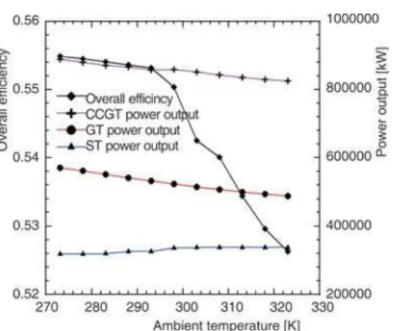
The variation of ambient temperature influences the GT and ST cycle performance and, consequently the overall performance of a CCGT. When the ambient temperature rise, the GT operates at off-design point and as a result the energy transfer to the HRSG varies (because of variation of exhaust gas temperature and mass flow rate). As well the ST cycle performance is influenced because the condenser now operates under off-design conditions and its performance is linked to the condenser cooling system adopted. In this case, the air temperature increase de-termines an increase in the cooling water temperature and then in the condenser pressure [20]. As an outcome, the ST electric power output decrease.
show the comparison between simulated power outputs of a CCGTvs. practical results from MARAFIQ CCGT power plant with effect the ambient temperature. It can be seen that in the both case the power output decreases with increase the ambient temperature. The simulated power output higher than the MARAFIQ CCGT power plant. The overall efficiency of a CCGT decreases with increases the ambient temperature. It is because of the decrease the thermal effi-ciency for GT compared with thermal effieffi-ciency of the ST cycle. The overall effieffi-ciency also de-creases due to inde-creases the losses of the exhaust gases. It can be seen that the CCGT overall
ficiency variation lies within the range between 52.6% and 55.5% when the ambient temperature varies between 273 K and 323 K as shown in fig. 5. While the ambient temperature rises, the CCGT HR increases (this is mean, the CCGT overall efficiency decreases) as shown in fig. 6.
Effect of compression ratio on CCGT performance
The effect of compression ratio on the overall efficiency of a combined cycle, total power out-put, GT power output and ST power outout-put, is shown in fig. 8, for ambient temperature 288.15 K (15 °C) and TIT 1600 K. The overall efficiency of a CC CCGT was found to increase with compres-sion ratio, and reach to maximum value at com-pression ratio 21, after that the overall efficiency was found decrease with increase the compres-sion ratio. The GT power output was found
in-crease with compression ratio until the compression ratio reach to 15, after that the GT power output was decrease with increase the compression ratio. The ST power output was decreasing with in-crease the compression ratio; it is because the compression ratio had an opposite effect on the steam generated in the ST power plant as shown in the fig. 9. Figure 9 shows decrease the steam generated in the ST cycle from 98 kg/s to 66.5 kg/s when the compression ratio increases from 9.6 to 26. The GT cycle power output, being higher in magnitude than the ST cycle power output, has a stronger in-fluence on the CCGT power output. This however, increases to an optimum value, after which the drop in ST cycle power output and the increasing the required power for compressor of a GT, cause the CCGT power output and overall efficiency to drop at higher compression ratio as shown in fig. 8. Figure 10 shows the comparison between simulated power outputs of a CCGTvs. practical results from MARAFIQ CCGT power plant with effect compression ratio. It can be seen that the power out-put from the CCGT power plant is much higher compare to practical CCGT (MARAFIQ CCGT) Figure 5. Effect of ambient temperature on the
overall performance CCGT
Figure 7. Comparison between simulated power outputs of a CCGTvs. practical results from MARAFIQ CCGT power plant with effect ambient temperature
power plant. In fig. 9, it can be seen that the HR of a CCGT deceased with increase the compression ratio, it is because the heat rate decreases with in-crease the overall efficiency.
Effect of TIT on CCGT performance
Figure 11 shows the effect of TIT on the power output of the GT, ST, CCGT cycle, and the overall efficiency of a CCGT at a constant compression ratio 15.7 and ambient temperature 288.15 K. However, the GT power output creases with increase the TIT, it is because in-crease the inin-creases the work of a GT relative to air compressor of a GT. The ST power output was found increasing with increase the TIT; it is because the steam generated in the ST cycle was found increased with increase the TIT as shown in the fig. 12. Figure 12 shows increase the steam generated in the ST cycle from 55 kg/s to 122 kg/s when the TIT increases from 1300 K to 1900 K, also this figure shown decreases the HR with increase the turbine inlet temperature. The CCGT total power output increases with increasing the TIT at constant air fuel ratio as shown in fig. 11. The different between the GT, ST cycle, and CCGT power output represent the significant improvement has been made from recovering the waste heat from the GT exhaust gases. The strong influence of TIT produces an increase in the power output in the CCGT power plant from 453 MW to 1287 MW when the TIT increases from 1300 K to 1900 K. The TIT has a positive effect on the overall performance of a CCGT. The over-all efficiency, like CCGT power output, increase almost linearly with the TIT. The overover-all effi-ciency also increases due to decreases the losses of the exhaust gases. It can be seen that the CCGT overall efficiency variation lies within the range between 46.6% and 59% when the TIT varies be-tween 1300 K and 1900 K as shown in fig. 11.
Figure 8. Effect of compression ratio on the overall performance CCGT
Figure 9. Effect of compression ratio on the CCGT HR and steam mass flow rate
Conclusions
The simulated modeling results shows that the influence of ambient temperature, compres-sion ratio, and TIT are significantly effect on the overall performance of CCGT power plant. The simulated modeling results shows as follow.
· The compression ratios and TIT are strongly influence on the overall efficiency of the combined cycle GT power plant.
· The increase of the ambient temperature has a significant influence on this type of power plant. The power output and the overall efficiency of a combined cycle GT power plant decrease with increase the ambient temperature.
· Higher overall efficiency for CCGT power plant was found about 59% with TIT 1900 K. · The overall thermal efficiency increases and total power output decreases linearly with
increase of the compression ratio with constant TIT.
Acknowledgments
The authors would like to thank University Malaysia Pahang for providing laboratory facilities and financial support under Doctoral Scholarship scheme (No. GRS100332).
References
[1] Godoy, E., et al., Families of Optimal Thermodynamic Solutions for Combined Cycle Gas Turbine (CCGT) Power Plants,Applied Thermal Engineering, 30(2010), 6-7, pp. 569-576
[2] Ameri, M.,et al., Exergy Analysis of a 420 MW Combined Cycle Power Plant,International Journal of Energy Research, 32(2008), 2, pp. 175-183
[3] Franco, A., Analysis of Small Size Combined Cycle Plants Based on the Use of Supercritical HRSG, Ap-plied Thermal Engineering, 31(2011), 5, pp. 785-794
[4] Ghazikhani, M.,et al., Two New High-Performance Cycles for Gas Turbine with Air Bottoming,Energy, 36(2011), 1, pp. 294-304
[5] Darwish, M. A., The Cogeneration Power-Desalting Plant with Combined Cycle: A Computer Program, Desaltination, 127(2000), 1, pp. 27-45
[6] Mitre, J. F.,et al., Modeling and Simulation of Thermoelectric Plant of Combined Cycles and its Environ-mental Impact,Thermal Engineering, 4(2005), 1, pp. 83-88
[7] Kaushika, S. C.,et al., Energy and Exergy Analyses of Thermal Power Plants: A Review,Renewable and Sustainable Energy Reviews, 15(2011), 16, pp. 1857-1872
Figure 12. Effect of turbine inlet temperature on the CCGT heat rate and steam mass flow rate Figure 11. Effect of TIT on the overall
[8] Chih, W.,Thermodynamics and Heat Powered Cycles: A Cognitive Engineering Approach, Nova Science Publishers, Inc. New York, USA, 2007
[9] Bouam, A.,et al., Gas Turbine Performances Improvement using Steam Injection in the Combustion Chamber under Sahara Conditions, Oil & Gas Science and Technology,Revue d’IFP Energies Nouvelles, 63(2008), 2, pp. 251-261
[10] Carapellucci, R., Milazzo, A., Repowering Combined Cycle Power Plants by a Modified STIG Configura-tion,Energy Conversion and Management, 48(2007), 5, pp. 1590-600
[11] Sheikhbeigi, B, Ghofrani, M. B., Thermodynamic and Environmental Consideration of Advanced Gas Turbine Cycles with Reheat and Recuperator,International Journal of Environmental Science and Tech-nology, 4(2007), 2, pp. 253-262
[12] Khaliq, A., Kaushik, S. C., Thermodynamic Performance Evaluation of Combustion Gas Turbine Cogeneration System with Reheat,Applied Thermal Engineering, 24(2004), 13, pp. 1785-1795 [13] Sullerey, R. K., Ankur, A., Performance Improvement of Gas Turbine Cycle,International Journal of
Turbo and Jet Engines, 25(2008), 3, pp. 209-219
[14] Razak, A. M. Y.,Industrial Gas Turbines Performance and Operability, Woodhead Publishing Limited and CRC Press LLC, Cambridge, England, 2007
[15] Avval, H. B., Ahmadi, P., Thermodynamic Modeling of Combined Cycle Power Plant with Gas Turbine Blade Cooling,Proceedings, 2ndIranian Thermodynamic Congress, Isfahan, Iran, 2007
[16] Ahmadi, P., Dincer, I., Thermodynamic Analysis and Thermoeconomic Optimization of a Dual Pressure Combined Cycle Power Plant with a Supplementary Firing Unit,Energy Conversion and Management,52 (2011), 3, pp. 2296-2308
[17] Meigounpoory, M. R.,et al., Optimization of Combined Cycle Power Plant Using Sequential Quadratic Programming, ASME 2008, Heat Transfer Summer Conference Collocated with the Fluids Engineering, Jacksnoville, Fla., USA, 2008, pp. 109-114
[18] Ibrahim, T. K.,et al., Study on the Effective Parameter of Gas Turbine Model with Intercooled Compres-sion Process,Scientific Research and Essays, 5(2010), 23, pp. 3760-3770
[19] Rahman, M. M.,et al., Thermodynamic Performance Analysis of Gas-Turbine Power-Plant,International Journal of the Physical Sciences, 6(2011), 14, pp. 3539-3550
[20] Melino, D. F., A Parametric Evaluation of Fogging Technology for Gas Turbine Performance Enhance-ment, Ph. D. thesis, Alma Mater Studiorum Universita’ Degli Studi Di Bologna, Bologna, Italy, 2000