ISSN 0104-6632 Printed in Brazil
Vol. 19, No. 04, pp. 433 - 439, October - December 2002
Brazilian Journal
of Chemical
Engineering
A SCREENING METHOD FOR THE OPTIMAL
SELECTION OF PLATE HEAT EXCHANGER
CONFIGURATIONS
J.M.Pinto
*and J.A.W.Gut
Department of Chemical Engineering, University of São Paulo, USP, Av. Prof. Luciano Gualberto, trav. 3, 38005508.900, São Paulo – SP, Brazil.
E-mail: [email protected] E-mail: [email protected]
(Received: March 5, 2002 ; Accepted: May 27, 2002)
Abstract - An optimization method for determining the best configuration(s) of gasketed plate heat exchangers is presented. The objective is to select the configuration(s) with the minimum heat transfer area that still satisfies constraints on the number of channels, the pressure drop of both fluids, the channel flow velocities and the exchanger thermal effectiveness. The configuration of the exchanger is defined by six parameters, which are as follows: the number of channels, the numbers of passes on each side, the fluid locations, the feed positions and the type of flow in the channels. The resulting configuration optimization problem is formulated as the minimization of the exchanger heat transfer area and a screening procedure is proposed for its solution. In this procedure, subsets of constraints are successively applied to eliminate infeasible and nonoptimal solutions. Examples show that the optimization method is able to successfully determine a set of optimal configurations with a minimum number of exchanger evaluations. Approximately 5 % of the pressure drop and channel velocity calculations and 1 % of the thermal simulations are required for the solution.
Keywords: plate heat exchanger, heat exchanger configuration, optimization, screening method.
INTRODUCTION
The plate heat exchanger (PHE) consists of a pack of gasketed corrugated metal plates, pressed together in a frame. The fluids flow through a series of parallel flow channels and exchange heat through the thin corrugated metal plates. The gasket design and the closed ports of the plates determine the fluid flow arrangement, which can be parallel, in series or one of several possible combinations of the two. The flow distribution, number of plates, type of gaskets and feed locations characterize the exchanger configuration.
To the author’s knowledge there is no rigorous design method for PHEs in the literature. Shah and
Focke (1988) have developed a detailed step-by-step design procedure for rating and sizing a PHE, which is however restricted to parallel flow arrangements. Optimization of the PHE flow arrangement to yield a minimum annual operating cost was studied by Jarzebski and Wardas-Koziel (1985). However, the use of approximate expressions to evaluate the PHE jeopardizes the optimization results.
solve the problem. An example of optimization is presented to illustrate the efficiency of the proposed method.
CONFIGURATION CHARACTERIZATION
To characterize the PHE configuration, six
distinct parameters are used: NC, PI, PII, φ, Yh and Yf,
which are described as follows:
NC : Number of Channels
The PHE is represented by a row of channels (the
space between two plates), numbered from 1 to NC.
The odd-numbered channels belong to side I, and the
even-numbered ones belong to side II. NCI and NCII
denote the numbers of channels on each side. If NC is
even, both sides have the same number of channels; otherwise side I has one more channel. Allowable values: 2, 3, 4, 5…
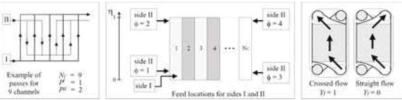
PI and PII : Number of Passes on Sides I and II
A pass is a set of channels where the main stream is split and distributed (see Fig. 1 for an example). For regular configurations, each side of the PHE
has the same number of channels per pass (NI and
NII). Passes with different numbers of channels are
not usual (Kakaç and Liu, 1998). Parameters NC, PI
the feed of side II is given by parameter φ, as shown
in Fig. (1) (Pignotti and Tamborenea, 1988). Allowable values: 1, 2, 3 and 4.
Yh : Hot Fluid Location
This binary parameter assigns the fluids to the
exchanger sides. If Yh = 1, the hot fluid is on side I,
and the cold fluid on side II. Otherwise, Yh = 0.
Yf : Type of Flow in Channels.
This binary parameter defines the type of flow inside the channels, which can be straight or crossed depending on the gasket type (Fig. 1). The crossed flow avoids the formation of stagnation areas, but the straight flow type is easier to assemble. It is not
possible to use both types together. If Yf = 1, then
the flow is crossed in all channels. If Yf = 0, the flow
is straight in all channels.
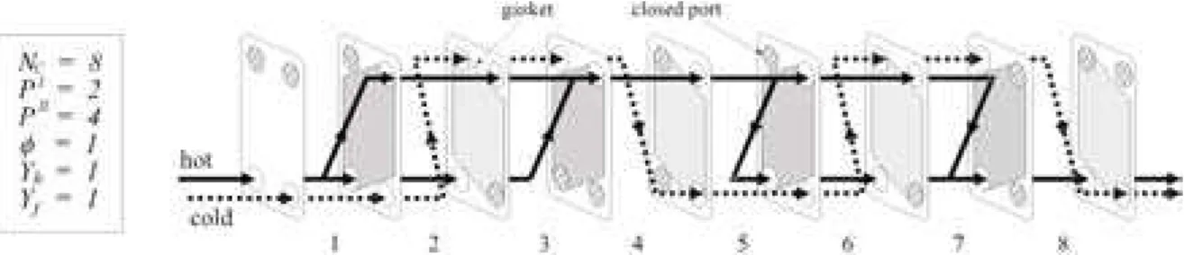
The six parameters can represent any regular configuration and an example of configurations for a nine-plate PHE is shown in Fig. (2). For any given
number of channels, NC, the five remaining
parameters have a finite set of allowable values, which limits the number of possible configurations, as shown in Fig. (3). The disperse pattern is due to
the variation in the number of integer factors of NCI
and NCII. For the range of number of channels
between 2 and 500 there are 284,976 different configurations.
Figure 2: Example of configuration for a PHE with nine plates (eight channels).
0 1,000 2,000 3,000 4,000 5,000 6,000 7,000
0 50 100 150 200 250 300 350 400 450 500
Number of channels – NC
Number of possible regular configurations
Figure 3: Number of possible regular configurations as a function of the number of channels.
Table 1: Identification of equivalent configurations for a given value of NC and Yf.
NC (P
I
/PII) Groups of equivalent values of φ
Reduction in the number of simulations
(1/1) ; (1/odd) ; (odd/1) {1, 3}; {2, 4} 50%
(1/even) ; (even/1) {1, 2, 3, 4} 75%
(odd/odd) ; (even/even) {1}; {2}; {3}; {4} 0%
odd
(odd/even) ; (even/odd) {1, 2}; {3, 4} 50%
(1/1) ; (1/odd) ; (odd/1) {1h, 3h, 1c, 3c}; {2h, 4h, 2c, 4c} 75%
(1/even)h {1h, 4h, 2c, 4c}; {2h, 3h, 1c, 3c} 75%
(even/1)h {1h, 3h, 2c, 3c}; {2h, 4h, 1c, 4c} 75%
(odd/odd) ; (even/even) {1h, 1c}; {2h, 2c}; {3h, 3c}; {4h, 4c} 50%
even
(odd/even) ; (even/odd) {1h, 2c}; {2h, 1c}; {3h, 3c}; {4h, 4c} 50%
configurations occurs due to the property of flow reversibility (Pignotti & Tamborenea, 1988), to the presence of single pass or to geometrical similarity (the configuration can be freely rotated or mirrored).
A methodology to detect equivalent configurations is shown in Tab. (1). For each set of
NC, PI, PII and Yf there are groups of values for
parameter φ that result in equivalent configurations.
In the case of even-numbered NC, there may be
equivalency between Yh = 0 and Yh = 1 because
sides I and II have the same number of channels and therefore can have the same numbers of passes. Consider for instance the exchanger shown in Fig.
(2), which is arranged for φ = 1 and Yh = 1;
according to Tab. (1), changing the sides of the
fluids (Yh = 1 Æ Yh = 0) will yield a different
although equivalent configuration.
CONFIGURATION OPTIMIZATION
The configuration optimization problem is formulated as the minimization of the number of
channels, NC, which is equivalent to minimizing the
exchanger heat transfer area or its fixed cost (Eq. 1). There are constraints on the number of channels
(NC), fluid pressure drops (∆Phot, ∆Pcold), channel
flow velocities (vhot, vcold) and exchanger
effectiveness (E), as shown in Constraints (2a) to (2f). The optimization model is also subject to the PHE model, necessary for calculation of the aforementioned variables (Constraint 3).
min F(NC, PI, PII, φ, Yh, Yf) = NC (1)
subject to
NCmin ≤ NC≤ NCmax (2a)
∆Photmin ≤ ∆Phot ≤ ∆Photmax (2b)
∆Pcoldmin ≤ ∆Pcold ≤ ∆Pcoldmax (2c)
vhotmin ≤ vhot (2d)
Constraint (2a) on the number of channels is related to the available number of plates and exchanger capacity. The minimum values for fluid pressure drop avoid large variations between the average fluid pressures that can bend the plates. Lower bounds on channel flow velocities avoid the formation of preferential paths or stagnation areas inside the channels.
The thermal and hydraulic modeling of the PHE (Constraint 3) was developed by Gut and Pinto (2001). The rigorous thermal model accounts for the variation in the overall heat transfer coefficient in the exchanger and consists of a system of differential and algebraic nonlinear equations, which can be solved by numerical methods. Assuming the heat transfer coefficient invariable, the rigorous model can be reduced to the so-called simplified thermal model, which consists of a system of linear ordinary differential equations and has an analytical solution. Since there is little difference between the main simulation results achieved by rigorous and simplified thermal models, the latter will be used for the optimization, keeping the former for final verification of the results.
The Screening Method
The proposed optimization procedure is based on the screening method, also employed by Daichendt and Grossmann (1994) for heat exchanger network optimization. In this procedure, constraints are successively used to remove infeasible and nonoptimal solutions of a MINLP problem, thus reducing its size and complexity.
In the optimization of a PHE configuration, the Constraint on the number of channels (2a) defines the initial set, IS, of possible configurations, formed by combinations of the five remaining parameters. An exhaustive enumeration procedure could be used to obtain the optimal configurations within this set; however, this procedure requires a large computational effort due to the large number of thermal simulations needed.
Since it is possible to calculate (∆P, v) prior to the
thermal simulation using average values for the fluid temperatures, the constraints on pressure drops and channel velocities (Constraints 2b to 2e) can be used to eliminate all infeasible elements in set IS. Therefore, a reduced set of configurations, RS, is generated. It is important to note that to obtain set
RS it is not necessary to calculate (∆P, v) for all the
configurations in IS because of the following:
A1) parameter φ has no influence over (∆P, v),
A2) (∆P, v) is independent for sides I and II. Thus,
for a given NC, the calculations are made only once
for each allowable number of passes,
A3) for a given NC, ∆P is proportional to the
number of passes; therefore, if ∆P > ∆Pmax is
verified, any configuration with a larger number of passes also results in an infeasible solution,
A4) for an even-numbered NC, sides I and II have
the same number of channels and therefore the same
allowable numbers of passes. In this case, (∆P, v)
will have the same value for Yh = 1 and Yh = 0.
Once set RS is obtained, the effectiveness Constraint (2f) is used to select the optimal set of configurations, OS. However, it is not necessary to thermally simulate all elements in RS because of the following:
B1) there are equivalent configurations with the
same effectiveness; thus only one needs to be simulated,
B2) if a search is conducted in increasing order of
NC, when the optimal set is found, all remaining
configurations with higher values of NC can be
neglected.
Since the influence of parameter Yf on the
convective coefficients and friction factor is usually
unknown, this parameter may be fixed prior to optimization, thus reducing the number of possible configurations by 50 %. Moreover, it is not possible to change the type of flow in an existing exchanger. Based on these principles, a screening algorithm is developed for the solution of the PHE configuration problem. The steps of the screening algorithm are as
follows. For this algorithm, Yf must have a given
value (Yf = 0 or 1). If there is available data on the
influence of Yf on the heat exchange and friction
correlations, this algorithm can be used once for each case and the results compared.
1. The required data for plate (corrugation pattern,
dimensions, area enlargement factor and thermal conductivity), hot and cold fluids (flow rate, inlet temperature, fouling factor and correlations for friction factor, convective heat transfer coefficients and physical properties) and constraints (lower and upper bounds for Constraints (2a) to (2f)) are read.
2. Initialization: RS = ∅ , NC(k) = NCmin , k = 1.
3. All allowable numbers of passes for sides I and II
(PIi, PIIj) are obtained for NCk.
4. Verification of constraints on pressure drop and
channel flow velocities:
4.1. The (∆P, v) pair is calculated for the cold fluid
located on side I for each one of the numbers of
passes PIi (in increasing order). If the constraints of
(∆P, v) are satisfied, the cold-fluid/sideI-pass pair is
selected. If ∆Pmax is exceeded, there is no need to
evaluate larger numbers of passes. This procedure is applied to the cold fluid located on side II for all the
numbers of passes, PIIj, thereby selecting the
cold-fluid/sideII-pass pairs.
4.2. The same procedure as that in step 4.1 is
applied to the hot fluid, obtaining the hot-fluid/sideI-pass and hot-fluid/sideII-hot-fluid/sideI-pass pairs.
5. The selected pairs of cold-fluid/sideI-pass and
hot-fluid/sideII-pass are combined to generate all
possible configurations with Yh = 0. Each
combination results in four configurations since φ
has four values equivalent to (∆P, v). The same
procedure is applied to the selected hot-fluid/sideI-pass and cold-fluid/sideII-hot-fluid/sideI-pass pairs, yielding
configurations with Yh = 1. All generated
configurations are stored in RS.
6. If NC(k) = NCmax, then proceed to step 7.
Otherwise, NC(k+1) = NC(k) + 1, k = k + 1 and return to
step 3.
7. Set RS is now complete. It contains all the
configurations that satisfy the constraints on pressure drop and channel velocity for both sides. Now the optimal set, OS, must be obtained.
they are stored in set OS and there is no need to simulate other elements of RS. Otherwise, proceed to
the next value of NC in set RS and return to step 9.
12.The rigorous thermal model is used to simulate
the nonequivalent elements in OS to verify the effectiveness results. In case of discrepancy (|Esimplified – Erigorous| / Erigorous ≤ ε), the rigorous model should be used in the previous simulations after step 8. Otherwise, the optimal solution is achieved.
OPTIMIZATION RESULTS
The gPROMS software (Process Systems Enterprise Ltd, 2000) is applied for solution of the simplified and rigorous thermal simulation models using the finite differences method. A computer program was developed to automatically run steps 1 through 8 of the screening algorithm to obtain set RS. The program uses the model assembling algorithm (Gut and Pinto, 2001) to generate all the input files for simulation with gPROMS, pointing out all equivalent configurations in RS.
It was verified that the number of channels per pass has a strong effect on the pressure drop, and consequently, about 98 % of the elements in IS are eliminated in the first part of the screening (steps 1 through 8). Compared to an exhaustive enumeration procedure, the screening method demands approximately 5 % of the required evaluations
of (∆P, v). Further, to obtain set OS only a few
to (4f).
2 ≤ NC≤ 150 (4a)
10 ≤ ∆Phot ≤ 20 psi (4b)
15 ≤ ∆Pcold ≤ 25 psi (4c)
vhot ≥ 0.20 m/s (4d)
vcold ≥ 0.30 m/s (4e)
94 ≤ E ≤ 95 % (4f)
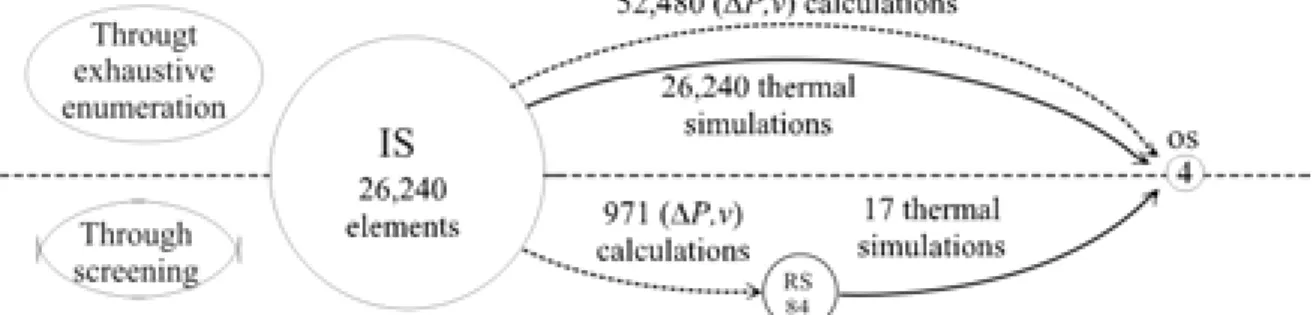
In this problem, IS has 26,240 elements and only
1.8 % of the (∆P, v) calculations and 0.06 % of the
simulations were necessary for the solution of the problem by the screening method. The comparative performance of the screening and enumeration methods is shown in Fig. (4). The set RS obtained
contains 84 configurations, ranging from NC = 43 to
NC = 144, with pass arrangements of 1/2, 2/3 and 2/4
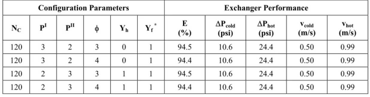
for hot fluid/cold fluid. The problem solution consists of two pairs of equivalent configurations, all with 120 channels, two passes for the hot fluid and three passes for the cold fluid, as shown in Tab. (2). The required CPU time in a DEC-Unix workstation for the simulations of the simplified model was under 1 min, and 5 min were necessary to validate the results using the rigorous model (the deviations in E were under 1 %).
Table 2: Optimal configurations obtained for the optimization example.
Configuration Parameters Exchanger Performance
NC PI PII φ Yh Yf *
E (%)
∆Pcold
(psi)
∆Phot
(psi)
vcold
(m/s)
vhot
(m/s)
120 3 2 3 0 1 94.5 10.6 24.4 0.50 0.99
120 3 2 4 0 1 94.4 10.6 24.4 0.50 0.99
120 2 3 3 1 1 94.5 10.6 24.4 0.50 0.99
120 2 3 4 1 1 94.4 10.6 24.4 0.50 0.99
* fixed prior to optimization
CONCLUSIONS
The configuration of a gasketed plate heat exchanger (PHE) was represented by a set of six distinct parameters and a methodology to detect equivalent configurations was presented. The problem of optimizing the PHE configuration was formulated as the minimization of the heat transfer area, subject to constraints on the number of channels, the pressure drop and channel flow velocities for hot and cold fluids and the exchanger thermal effectiveness as well as the PHE simulation model. Since it is not possible to derive a mathematical model of the PHE that is explicitly a function of the configuration parameters, a mixed-integer nonlinear programming (MINLP) approach could not be used. A screening procedure was then proposed to solve the optimization problem. In this procedure, subsets of the constraints were successively used to eliminate infeasible and nonoptimal elements from the set defined by the bounds on the number of channels. An algorithm was developed to perform the screening with minimum computational effort. Examples show that this algorithm can successfully select a group of optimal configurations (rather than a single solution) for a given application using a very reduced number of thermal simulations.
ACKNOWLEDGMENTS
The authors would like to thank FAPESP for its financial support (98/15808-1, 00/13635-4).
REFERENCES
Daichendt, M.M. and Grossmann, I.E. (1994). A Preliminary Screening Procedure for MINLP Heat Exchanger Networks Synthesis Using Aggregated Models. Trans IChemE, vol. 72A, pp. 357-363. Gut, J.A.W. and Pinto, J.M. (2001). Modeling of
Plate Heat Exchangers with Generalized Configurations. Proceedings of the 16th Brazilian Congress of Mechanical Engineering (COBEM 2001), vol. 4, pp.376-385 (CD-ROM).
Jarzebski, A.B. and Wardas-Koziel, E. (1985). Dimensioning of Plate Heat-Exchangers to Give Minimum Annual Operating Costs. Chemical Engng Research and Design, vol. 63, no. 4, pp. 211-218.
Kakaç, S. and Liu, H. (1998). Heat Exchangers: Selection, Rating and Thermal Design. CRC Press, New York.
Kandlikar, S.G. and Shah, R.K. (1989). Multipass Plate Heat Exchangers – Effectiveness-NTU Results and Guidelines for Selecting Pass Arrangements. ASME J. of Heat Transfer, vol. 111, pp. 300-313.
Pignotti, A. and Tamborenea, P.I. (1988). Thermal Effectiveness of Multipass Plate Exchangers. Int. Journal of Heat and Mass Transfer, vol. 31, no. 10 Oct., pp. 1983-1991.
Process Systems Enterprise Ltd. (2000). gPROMS Introductory User Guide, Release 1.7. London. Shah, R.K. and Focke, W.W. (1988). Plate Heat