Estimation of the Plain High-Cycle Fatigue Propagation
Resistance in Steels
Mirco D. Chapetti
INTEMA (CONICET-UNMdP), J.B. Justo 4302, (B7608FDQ) Mar del Plata, Argentina
Received: August 28, 2001; Revised: March 7, 2002
In this work a method to estimate the high cyclic fatigue propagation life of steel specimens under constant loading is presented. This method is based in experimental evidence that the fa-tigue limit represents the threshold stress for the propagation of nucleated cracks, so that both the fatigue limit and the fatigue resistance depend on the effective resistance of the microstructural barriers that have to be overcome by the nucleated cracks. It is proposed also, that in those cases where the number of cycles that is necessary for the nucleation of the cracks can be neglected, the fatigue crack propagation life can be taken as an estimation of the total fatigue life.
The high cycle fatigue propagation life of a structural steel of the type JIS 10C is estimated.
Keywords:high cycle fatigue, microstructural barriers, microstructural threshold, mechani-cal threshold
1. Introduction
The initiation and early propagation of fatigue cracks are strongly influenced by the microstructure and the grain size, and they seem to be related with the fatigue limit of metals1-5. The fatigue limit as well as the fatigue resistance
depend on the effective resistance of the microstructural barriers that have to be overcome by the cracks. Each of these barriers has a characteristic dimension and a critical stress range associated with its resistance to crack propaga-tion. The plain fatigue limit is given by the strongest micro-structural barrier, since that resistance is generally greater than the resistance to crack nucleation. On the other hand, above the fatigue limit and for a given stress range, each barrier have an associated number of cycles that it is neces-sary to be overcome by the crack. The control of these bar-riers by means of thermo-mechanical treatments (in terms of their position, size and resistance), would allow obtain-ing materials with high resistance to fatigue.
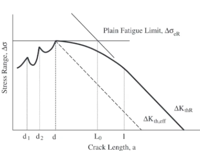
Figure 1 shows a plot relating the crack threshold stress with the crack length2,4. It shows the threshold between
propagating and non-propagating cracks for three regimes. Because of the strongest microstructural barrier to fatigue crack propagation is generally placed at a given distance d
from the material surface, up to a certain crack size (a = d) the crack is non-damaging with respect to the fatigue limit. For a microstructurally short crack (MSC, crack length of the order of the microstructural dimensions) initiated from a plain surface the fatigue strength ∆σeR defines the critical nominal stress range needed for continued crack growth (microstructural threshold). If the applied stress range ∆σ is smaller than ∆σeR, cracks included in the microstructurally-short crack regime are arrested at microstructural barriers.
On the other hand, for long cracks the fatigue limit de-creases with increasing crack size5-7. The threshold for long
cracks (LC, crack length greater than that at which crack closure is fully developed) is defined in terms of the thresh-old value of the stress intensity factor range, ∆KthR, thus long cracks can only grow by fatigue if the applied stress intensity factor range ∆K is greater than ∆KthR.
In the physically short crack regime (PSC), which cor-responds to the transition between microstructurally short and long crack regimes (MSC and LC), the threshold is below ∆σeR and ∆KthR, both being a function of the stress ratio R (minimum to maximum applied stress). Although in this regime the influence of microstructure is still impor-tant, it is the development of crack closure which governs the threshold level.
The limit between MSC and PSC regimes is defined by
d while the PSC and LC regimens are delimited by l. The length d is given by the distance between the strongest micro-structural barriers, but can also be defined other lengths, d1,
d2, etc (distance between inclusions, precipitates, second phases, etc). For a typical low carbon steel, the values of d
and l are about 0.05 mm and 0.5 mm respectively.
2. Crack Growth Threshold
In order to obtain an expression for the material crack grow resistance as a function of the crack length (including the short crack regime), it is necessary to take into account the development of the crack closure component. This crack closure component acts as an extrinsic crack growth resist-ance and its magnitude increases by increasing the crack length, till a value that depends on the stress ratio R.
McEvily and Minakawa have proposed6, based on an
Analysis of El-Haddad and coworkers results for short cracks growing from holes7, that the components of the stress
in-tensity factor range corresponding to crack closure, as a function of crack length, can be given by the following expression:
∆KC = ∆KCR (1 - e-ka) (1)
Where ∆KCR is the crack opening level for a macroscopic crack that depends on the stress ratio R, k is a material con-stant, and a is the crack length expressed in mm. In this way, the development of the crack closure is defined by k. The parameter k is obtained experimentally, by analyzing (for each material) the development of crack closure as a function of crack length. However, it is possible to estimate it by defining the crack depth at which the crack closure component is totally developed. Tokaji et al.8 have observed
that this crack length can be defined equal to 3d + 0.15 mm,
where d is the predominant microstructural dimension and can be related with the position of the strongest microstruc-tural barrier. In expression (1), ∆KC = 0.63 ∆KCR when k a = 1. If we suppose that the crack closure component has developed when a = 3d + 0.15 mm and k.a = 1, we get the following expression to estimate k:
Now then, it is necessary to add the intrinsic resistance to crack propagation to the crack closure component ∆KC. Different authors have considered this intrinsic resistance as equal to the effective mechanical threshold for long crack, ∆Keff,th, defined as the difference between the mechanical threshold for long cracks ∆KthR and its corresponding crack opening level ∆KCR5-7. Using this definition the position of
the strongest microstructural barrier (a kind of intrinsic crack length), is defined by ∆Keff,th and ∆σeR (the plain fatigue limit). In recent works carried out by Chapetti et al.4,9, the
position and the effective resistance of microstructural bar-riers and their relation to the fatigue strength were analyzed and modeled. It was shown that the strongest barrier de-fines the plain fatigue limit and the fatigue blunt-notch sen-sitivity. According to these results, it seems to have more physical meaning to use the position d of the strongest micro-structural barrier and the plain fatigue limit ∆σeR to define an intrinsic resistance to crack propagation. This intrinsic resistance can be considered as a microstructural threshold to crack propagation and can be then defined as follows:
d KdR=∆σeR π
∆ (2)
In this way we can define the crack closure component ∆KCR as the difference between the mechanical threshold and the microstructural one, as follows:
(3)
Finally, the material resistance to crack propagation as a function of crack length ∆Kth(a), can be estimated as:
(4)
This expression is defined from a crack length d equal to the position from the surface of the strongest barrier, and can be obtained with the following data: the plain fatigue limit ∆σeR, the position d of the strongest microstructural barrier, and the mechanical threshold for long cracks ∆KthR. The influence of the stress ratio R is implicit in ∆σeR and ∆KthR. Figure 2 shows schematically the defined threshold to crack propagation.
15 0 3
1
. d k
+ =
K
thR CRK
=
∆
−
∆
K
dR∆
Figure 1. Material crack growth threshold as a function of the crack length, showing the border between propagating and non-propagating cracks.
(
)
1 3( 0.15)
− ∆
− ∆ + ∆ =
∆ +
− −
d d a
dR thR
dR
th K K K e
3. Applied Crack Driving Force
Guiu and Stevens10. showed that the extension force for
the nucleation and growth of “sub-critical” or “small” fa-tigue cracks comes from both the external load (external crack extension force), and the elastic energy released from the local region near the crack tip (local crack extension force). The local energy source is defined as the strain en-ergy stored in the form of internal stress fields generated by cyclic plastic deformation. The accumulation of strain en-ergy in local regions during cyclic deformation, or fatigue, is a consequence of the inhomogeneous deformation and the irreversibility of local shear strain. Examples of this are the formation of persistent slip bands (PSBs)11.
On the other hand, the external crack extension force increases with crack growth and is given by the applied stress intensity factor range ∆K, defined as
(5)
where ∆σn is the nominal stress range, a is the crack length, and Y is a geometric factor that takes the crack as-pect radio into account
Related with the development of the local crack exten-sion force is the inherent surface strain concentration phe-nomenon12,13. Favorably orientated grains experiences the
largest amount of surface deformation and the greatest amount of localized slip. Localized slip allows, for instance, PSBs to develop at the surface of the favorably orientated grains which become them a preferred site of crack
initia-tion. H. Abdel-Raouf and coworkers12,13 found that the
lo-cal strains in surface grains favorably orientated for slip is much larger than the nominal applied cyclic strain. On the other hand, in the interior of the material the grains support each other and as more of this constraint is experienced the local strain decreases with depth into the specimen, eventu-ally approaching the nominal strain range. The strain con-centration due to different grain orientations and the lack of constraint at the surface was expressed by the inherent strain concentration factor12:
(6)
were q is a constant, a is the crack depth, M is the grain size (microstructural parameter controlling the strain de-cay), α is a decay constant depending upon the deforma-tion character (equal to 0.6 for aluminum 2024-T312), and
∆ε and ∆εn are the local and nominal cyclic strain range respectively.
At the free surface, were a = 0, Qe has a value of 1+q= 6.3 for the grain most favorably orientated for slip in polycrystalline material12. Consequently, the constant q
in Equation (6) takes a value of 5.3.
In the present model, a kind of local crack driving force is considered when defining the threshold curve to crack propagation, which is taken into account as a damage that decreases the threshold ∆Kth as the crack length decreases. However, to take into account the weakest surface grain configurations where the cracks usually nucleate, it seems better to take into account an extra surface stress concentra-tion at the first two or three microstructural unities (for in-stance grain boundaries). This is done by using expression (6) with q = 1, α = 1 and M = d, this giving a local stress concentration equal to two, at the surface. The stress con-centration decreases to one at a depth equal to three or four times the value of d. The applied stress intensity factor range ∆K that takes into account both the external crack driving force and the local stress concentration can be then defined as follows using expressions (5) and (6) with α = 1 and M =d:
(7)
Where the term into parenthesis takes into account the surface stress concentration effect.
We suppose here that the geometric factor Y is equal to 1. Better estimations can be obtained if the crack aspect ratio is known as a function of crack length.
Estimation of the High Cyclic Fatigue Life
The fatigue life of materials, components and struc-tures is usually divided in two phases: the initiation of a Figure 2. Schematic of the proposed material crack growth
thresh-old as a function of crack length.
a Y
K
n π
σ ∆
∆ =
M a exp q n
Q 1
− +
=
= α
ε ∆
ε ∆ ε
1000 exp
1 a
M a Y
K σ π
−
crack and its propagation to a critical length that produce the failure of the component or structure. This division states that initiation is not associated to propagation and it is historical. Until several years ago, it was usual to as-sume that the fatigue limit of a plain component (without notches), is defined by the stress level bellow which it is impossible to nucleate a crack. However, new evidence and models1,4,9 show that the fatigue crack initiation takes
place immediately in almost all practical cases at stress levels above and just below the fatigue limit, and this limit can be defined with better precision as that below which initiated cracks are arrested by microstructural barriers. In this way, the fatigue limit is defined as a threshold to crack propagation.
In high cyclic fatigue, if we define the initiation period as that given by the number of cycles to initiate a crack of length similar to the microstructural dimension d, the total crack propagation period till fracture is defined as the number of cycles necessary to propagate the crack from a depth d given by the position of the strongest microstruc-tural barrier, to a critical length ac defining the failure of the component.
Quantitative analysis of fatigue crack growth requires a constitutive relationship of general validity be established between the rate of fatigue crack growth, da/dN, and some function of the range of the applied stress intensity factor, ∆K (crack driving force). Besides, it has to take into ac-count the threshold for the whole crack length range, that is to say, it need an expression for the resistance of the mate-rial for crack propagation as a function of crack length. It is proposed that the following relationship meets these require-ments 14,15:
(8)
Where C* and m are environmentally sensitive mate-rial-constants, and ∆Kth is the crack growth threshold as a function of a and R and represents the effective resistance of the material to fatigue crack propagation.
Finally, we could obtain the fatigue life to crack propa-gation between two given crack length for a given material, by integrating expression (8) and using expressions (7) and (4) for ∆K y ∆Kth, respectively.
4. Application Example
In order to apply the proposed method, experimental results obtained from the literature are used. In reference16
(Tokaji et al.), the growth characteristics of small fatigue cracks were studied under rotary bending in a low carbon steel prepared with an average ferrite grain sizes of 24 mm, and were compared with the growth characteristic of large
through cracks in fracture mechanics type specimens. We have chosen this work because it has almost all data we need to apply equation (8). The material used in this study was a low carbon steel (JIS S10C), which a chemical com-position (wt%) of 0.11C. 0.20Si, 0.38Mn, 0.013P and 0.019S. Rotary bending fatigue tests (R –1) were performed at room temperature in laboratory air. Because the relation-ship between da/dN and ∆K , as well as ∆KthR for long cracks were obtained for R 0.05, C* and m constants and ∆KthR for R –1 from reference17 were used. According to the
ob-servation made by Tokaji et al., most of the crack initiated within ferrite grains.
The following data were finally used: ∆σeR = 440 MPa,
d = 0.024 mm, ∆KthR = 13.5 MPa m1/2, C* = 4.11 x 10⁻⁹ mm/
cycle, m = 3.71. The mechanical properties were 286 MPa yield stress, 433 MPa tensile strength, 977 true failure stress, 33% elongation and 70% reduction of area.
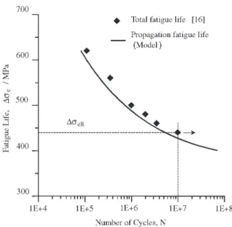
Figure 3 shows the estimated fatigue crack propagation life together with the experimental total fatigue life data obtained experimentally by Tokaji et al.18. It can be seen
that the estimated fatigue life is conservative in approxi-mately 40% with respect to experimental results in the hold-analyzed range. Regarding the fatigue limit the estimation is conservative in only 5%, and this is related with the fact that the fatigue limit can be defined as a microstructural threshold to crack propagation. Better estimations could be done if the crack aspect ratio is known as a function of the crack length.
Figure 3. Estimated high cyclic fatigue propagation life for a low carbon steel of the type JIS 10C. Experimental results of the total fatigue life from Tokaji et al.16 are also shown.
(
K K)
C dn
da m
th * ∆ −∆
The critical crack length ac defining the failure of the component was taken as equal to 2 mm. It is worth noting that the proposed model take into account the short crack regime, from a crack similar to the microstructural dimen-sion, which is relatively very small comparing with the one usually considered as nucleated crack in engineering terms. It is in the short crack regime where most of the fatigue life is spent to propagate the crack. On the other hand, the criti-cal crack length ac has usually little influence in the fatigue crack propagation life of components like fatigue specimens. For instance, if we change ac from 2 mm to 3 mm, the fa-tigue life increase only 0.5%.
In high cyclic fatigue, and for those cases where the ini-tiation period can be neglected, it is possible to estimate the total fatigue life as the number of cycles necessary to propa-gate the crack from a depth d given by the position of the strongest microstructural barrier, to a critical length ac de-fining the failure of the component.
5. Conclusions
A method to estimate the high cyclic fatigue propaga-tion resistance is presented for steels. A material resistance to crack propagation as a function of crack length was de-fined. The difference between the total driving force and the material resistance to crack propagation defines the ef-fective driving force applied to the crack. By knowing the crack growth rate as a function of this effective driving force for a given material, it is possible to estimate the high cyclic fatigue life for a given crack length range. The initial crack length would be given by the position of the strongest micro-structural barrier if the material were free of cracks or crack like flaws. The final crack length can be defined according to critical parameters related with the loading conditions of the analyzed components.
The presented method was applied to estimate the high cyclic fatigue propagation life for a low carbon steel of the type JIS 10C, which represents a sub-estimation of about 40% of the total high cycle fatigue life in the hold analyzed range. The method can used to estimate the total fatigue life in those cases when the nucleation period can be neglected, and for stress levels near the fatigue limit (high cycle fa-tigue).
Acknowledgments
The author wishes to express his thanks for funding pro-vided by CONICET (Consejo Nacional de Investigaciones Científicas y Técnicas), and by Agencia Nacional de Promoción Científica y Tecnológica (PICT’98 12-04585/ 6), Argentina.
References
1. Taylor, D.; Knott, J.K. Fat. Engng. Mater. Struct, v. 4, n. 2, p. 147-155, 1981.
2. Miller, K.J.; Ibrahim, F.E. Fat. Engng. Mater. Struct., v. 5, n. 3, p. 223-232, 1982.
3. Lankford, J. Fat. Engng. Mater. Struct., v. 8, n. 2, p. 161-175, 1985.
4. Chapetti, M.D.; Kitano, T.; Tagawa, T.; Miyata, T. Fa-tigue & Fracture of Engineering Materials & Structures, v. 21, p. 1525-1536, 1998.
5. Tanaka, K.; Nakai, Y.Transactions of the ASME, v. 106, p. 192-199, 1984.
6. McEvily, A.J.; Minakawa, K. Engng. Fract. Mech., v. 28, n. 5/6, p. 519-527, 1987.
7. El Haddad, M.H.; Topper, T.H.; Smith, K.N. Engng. Fract. Mech., v. 11, p. 573, 1979.
8. Tokaji, K.; Ogawa, T.; Harada, Y.; Ando, Z. Fatigue and Fract. Engng. Mater. Struct., v. 9, n. 1, p. 1-14, 1986. 9. Chapetti, M.D.; Kitano, T.; Tagawa, T.; Miyata, T.
Inter-national Journal of Fatigue, v. 21, n. 1, p. 77-82, 1999. 10. Guiu, F.; Stevens, R.N. Fatigue Fract Engng Mater
Struct., v. 13, p. 625-635, 1990.
11. Mughrabi, H.; Ackermann, F.; Herz, K. ASTM, STP 675, p. 69-105, 1979.
12. Abdel-Raouf, H.; Topper, T.H.; Plumtree, A. Scripta Metall et Mater, v. 25, p. 597-602, 1991.
13. Abdel-Raouf, H.; DuQuesnay, D.L.; Topper, T.H.; Plumtree, A. Int J Fatigue 14, n. 1, p. 57-62, 1992. 14. Fuchs, H.O. “Metal Fatigue in Engineering”, 1980. 15. Zheng, X.; Hirt, M.A. Engng Fract. Mech., v.18, n. 5, p.
965-973, 1983.
16. Tokaji, K.; Ogawa, T.; Harada, Y. Fatigue Fract. Engng. Mater. Struct., v. 9, n. 3, p. 205-217, 1986.