Experimental Validation of the New Modular
Application of the Upper Bound Theorem in
Indentation
Carolina Bermudo*, Francisco Martín, María Jesús Martín, Lorenzo Sevilla
Department of Civil, Material and Manufacturing Engineering, University of Malaga, Malaga, Spain
Abstract
Nowadays, thanks to the new manufacturing processes, indentation is becoming an essen-tial part of the new arising processes such as the Incremental Forming Processes. This work presents the experimental validation of the analytical model developed for an indenta-tion-based process. The analytical model is originated from the Upper Bound Theorem ap-plication by means of its new modular distribution. The modules considered are composed of two Triangular Rigid Zones each. The experimental validation is performed through a se-ries of indentation tests with work-pieces of annealed aluminium EN AW-2030 and punches of steel AISI 304, under plane strain conditions. The results are compared with the ones ob-tained from the application of this new modular distribution of the Upper Bound Theorem, showing a good approximation and suitability of the model developed for an indentation-based process.
Introduction
Indentation has been considered as a secondary manufacturing process [1] until now. Today, new manufacturing processes, such as the incremental forming processes (IFP), are being de-veloped and indentation becomes an essential part of them. In the IFP, the work-piece final shape is obtained progressively. Since the dies used are smaller than the work-piece, the final shape is obtained gradually by repetitive applications of different impressions.
The IFP provides several advantages over the conventional manufacturing processes. As mentioned in [2]<<...There are economical reasons to use incremental forming while there are also several technological advantages. In particular, the flexibility and the lower forces compared to die-defined forming are important as well as the properties and formability of the finished
parts...>>. Thanks to these advantages, the interest on incremental bulk processes is growing
[3]. Consequently, the manufacturing industry demands new studies on indentation processes in order to perform more suitable applications according to their different perspectives.
In the indentation process, a die or punch produces an impression on the material or work-piece, causing permanent plastic deformation. If this action is consecutively repeated, different and complex shapes can be achieved. An implementation of the indentation process as a
a11111
OPEN ACCESS
Citation:Bermudo C, Martín F, Martín MJ, Sevilla L (2015) Experimental Validation of the New Modular Application of the Upper Bound Theorem in Indentation. PLoS ONE 10(3): e0122790. doi:10.1371/journal.pone.0122790
Academic Editor:Jose Manuel Garcia Aznar, University of Zaragoza, SPAIN
Received:September 10, 2014
Accepted:February 15, 2015
Published:March 31, 2015
Copyright:© 2015 Bermudo et al. This is an open access article distributed under the terms of the
Creative Commons Attribution License, which permits unrestricted use, distribution, and reproduction in any medium, provided the original author and source are credited.
Data Availability Statement:All relevant data are within the paper.
Funding:This work was supported by FPU program of the Ministry of Education and University of Malaga
–Andalucia Tech Campus of International
Excellence. The funders had no role in study design, data collection and analysis, decision to publish, or preparation of the manuscript.
concatenation of indentations is exemplified by the Localized-Incremental Forming Processes (LIFP) [4]. Thus, LIFP is based on the sequence of specific compression processes. The work-pieces are larger than the tools or dies; therefore, global compression effects can be achieved in the work-piece by the concatenation of successive compression in predetermined positions. Multiple Indentation Processes (MIP) makes up another example of this. As explained in [5],
<<...In the multiple indentation process, a force is applied on the work-piece surface by a punch to produce an impression on the material. The compression process causes permanent plastic de-formations that, repeated incrementally, let forming the work-piece by a localised-incremental
forging action...>>which can be compared with the shot-peening processes [6,7]. The LIFP
and the MIP are considered as part of the so-called IFP [8]. This kind of processes requires less effort to achieve the needed deformation and the dies are, in general, geometrically simpler. Additionally, another advantage is that they can be entirely implemented in CNC machines with greater flexibility.
IFP are a recent alternative to traditional plastic deformation processes, such as forging or cold/hot rolling. These processes are referred to as traditional due to their wider development in the manufacturing industry. IFP processes arise in order to address the profound changes that are taking place in the industry, as a way to enable the current objectives of the modern in-dustry. However, the industrial applications are still very restricted.
For this reason, as pointed out in [9],<<...the demand for the simulation of incremental bulk forming processes is high. However, the computation times for the simulation of these pro-cesses are still unsatisfactorily long and thus, their application is deterred...>>. Hence, a new modular distribution of the application of the Upper Bound Theorem (UBT), by means of modules of Triangular Rigid Zones (TRZ) is performed in this paper. This new method pres-ents an alternative to the computational methods currently used in the industry, such as nu-merical methods or the Finite Element Method (FEM).
As can be seen, the study and analysis of IFP, where the indentation process takes place, is being a recurrent topic of research [10,11]. The implementation of these processes is becoming imperative to the industry in order to (be able to) offer a competitive production.
In this paper, IFP are approached as a set of successive indentations. In fact, the simpler case of study accounts as an indentation each time the punch compress the work-piece. This research reduces the analysis to an indentation case, showing the alternative resolution of the process by the optimized Upper Bound Theorem method (UBT).
In the study of the indentation process by the application of the UBT, the TRZ alternative is the kinematic-geometrical option [12] that allows reaching a more accurate solution and adds a strong capacity of analysis of the principal factors involved in the deformation process.
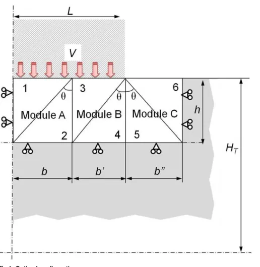
The modular application of the UBT, implemented by F. Martín in 2009 [13], shows an im-proved approximation to the real effort values that are needed in the deformation processes studied [14,15]. After the appropriate model review for an indentation process, the optimal model is the one inFig 1, being 2Lthe total width of the punch,HTthe total height of a quarter
of the work-piece studied,hthe modules, height,Vthe punch speed andθthe modules
optimal angle.
The analysis is proposed under Plane Strain conditions. Under this work restriction, the ma-terial offers its higher strength to deformation whenτ=k,τbeing the shear stress andkthe
yield strength in shear. Therefore, the value of the dissipative power, due to the internal energy, cannot exceed the outcome value ofksv,sbeing the length that corresponds to the
disconti-nuity line of the tangential velocity andvthe velocity in these discontinuities.
Also, under a plane strain hypothesis, the UBT, on general terms, expresses that<<...The work realised by the superficial strengths of real traction (or compression) on a rigid-perfect plas-tic body is lower or the same that the realized by the superficial strengths of traction (or compres-sion) corresponding to any other field of admissible kinematic velocities...>>[16]
Then,Eq 1shows its general expression
Z
Sv
TividSv
Z
SD
k½ v dS Dþ
Z
SF
Tivi dSF ð1Þ
Being:
Ti: External strengths applied on the work-piece;
vi: Real velocities field
Sv: Surfaces where external loads are applied;
SD: Discontinuity Surfaces
vi: Kinematically admissible virtual velocities field
Fig 1. Optimal configuration.
SF: External surfaces exposed to external surface stresses
Once the analytical model applicable under the UBT by its TRZ module configuration has been established and the final model optimization for the study of the indentation process im-plemented, a validation of the application through experimental testing, is necessary in order to determine the suitability of the method.
Materials and Methods
Preparation of the Test
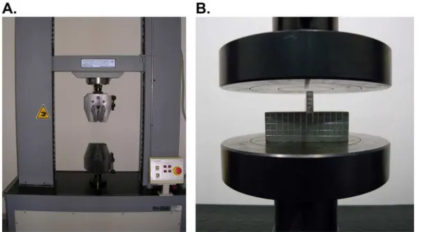
The trials were conducted with a tension-compression machine (Fig2Aand2B) which was con-figured to apply continuous compression forces until the required indentation depth is achieved. This machine has a maximum load capacity of 100kN. Therefore, it is essential to work with ma-terials endowed with wide range of deformation within the available strain values.
For the indentation tool, a 3 mm wide punch made of steel AISI 304is used. The work-piece is obtained from a 50x50x2000 mm square section bar of Aluminium EN AW-2030 (UNE-EN 573–1) [17]. The work-pieces final size is 50x50x30 mm, since the necessary depth to be able to work in Plane Strain conditions amounts to 30 mm. To achieve Plane Strain conditions, the work-piece depth should be at least 6 to 10 times the surface where the load is applied [18].
The material choice was made searching for a material commonly used in the industry. The aluminium alloy considered is often used in the aircraft structures manufacture, usually after having been subjected to different thermal-mechanical treatments. The principal alloying ele-ment in these aluminium alloys is copper. Previous tests where made with lead and tin due to their higher ductility and lower effort requirements to accomplish the expected plastic defor-mation. The suitability of the trial was analysed through the former tests; consequently, a spe-cial tool for the punch was designed. The analysis revealed that, at high velocities, the punch tended to tilt.
Thus, a clamp system was needed. A stabilizing system for the indenter (Fig 3A) was manu-factured to prevent the slippage of the punch along the compression plates and achieve a
Fig 2. Preparation of the test.The tension-compression machine (A); and the compression plate tools used (B).
complete and proper deformation of the work-piece. The designed tool is composed of two clamping screws that push a horizontal steel bar, called clamping bar, which, in turn, performs a uniform pressure over the indenter. This support (Fig 3B) provides a wider base to the in-denter, avoiding leaning.
To achieve an adequate depth during the indentation test by providing strain values lower or equal to 100 kN, the aluminium work-pieces need to be processed. The material is subjected to a controlled annealing treatment (Fig 4), thereby attaining aluminium work-pieces with dif-ferent properties from the initial work-pieces subtracted from the aluminium bar. This new al-uminium state allows bigger deformations with lower efforts so that it can be plastically deformed with ease using the available tension-compression machine.
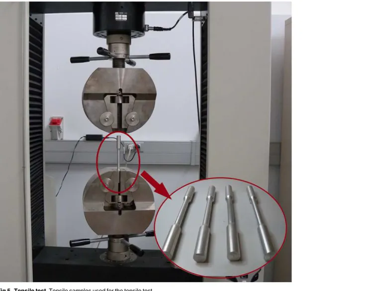
In addition to this, the correct implementation of the new modular distribution of the UBT requires knowing both, the strength coefficientKand the strain-hardening (or work-hardening) exponentnof the new aluminium obtained after the annealing process. Since the characteristics of the aluminium obtained after the annealed treatment are different from the one considered before and consequently thenandKcoefficients are also different and unknown, a series of ten-sile tests are implemented in order to acknowledge them (Fig 5). To this effect, a set of tensile samples (Fig 5) are manufactured according to the UNE-EN ISO 6892–1 [19] (Table 1) which undergo the same cycle annealing as the work-pieces.
After the tensile test is conducted (Fig 6), the stress-strain curve can be plotted. By applying the standard E 646–00 [20] used for the determination ofnandK, each value is obtained for aluminum EN AW-2030 after annealing. These values aren= 0.26 andK= 404.66 MPa.
Fig 3. Punch fastening tool.Tool parts for the punch fastening (A); and the tool assembled (B).
doi:10.1371/journal.pone.0122790.g003
Fig 4. Annealing cycle.
Eventually, implement the characteristics of the material in the UBT analysis and obtaining the efforts needed to achieve the plastic deformation specified is possible.
Indentation Test
In order to complete the indentation test, ensuring the centering of the punch during the whole process is essential. For this reason, block patterns are used to guarantee the correct position (Fig 7A). After securing the indenter with a pre-load of 50 Newton, the block patterns can be removed (Fig 7B).
Once the whole system is established, an indentation of 6 mm is conducted. The indentation depth cannot be increased to avoid excessive damage of the work-piece during deformation. Knowing that overcome the tensile strength limit is not intend, an excessive damage is consid-ered when cracks start to appear in the work-piece.
In order to establish the speed influence on the work hardening effect of the selected materi-al, various tests with different strain rates were performed. To obtain a right mean of results, three trials are carried out for each studied speed, 4 mm/min and 60 mm/min, as well as two
Fig 5. Tensile test.Tensile samples used for the tensile test.
trials for extreme speeds, 400 mm/min and 0.6 mm/min in order to study the material behavior in a wider range of speeds.
Each tested work-piece was given a code for identification, as follows:
EX1 X2 X3 A1 X4
Being:
A1: Material of the specimen
X1: Number of specimen X2: Speed (mm/min) X3: Depth of the indentation
X4: Dimensions of the specimen (mm)
The main performed tests are presented inTable 2.
Upper Bound Approach
Regarding the UBT approach, only the Infinite case has being considered (Fig 1), since the con-figuration of the Finite case analyzed in previous studies [21] is customarily identified with pro-cesses that differ from indentation and are more focused on sheet metal treatment,
consequently remaining out of the scope of this study.
Table 1. Standard cross-sectional specimens (UNE-EN ISO 6892–1).
Proportionality coefficient Diameter (mm) Initial length between marcs Minimum length of the calibrated part (mm)
c d Lo¼c
ffiffiffiffiffiffi
So
p L
c
5.65 20 100 110
5.65 14 70 77
5.65 10 50 55
5.65 5 25 28
doi:10.1371/journal.pone.0122790.t001
Fig 6. Tested samples.Stress-strain curve and tensile samples after tensile test.
Thanks to the modular consideration, the analysis can be performed module by module. A weighted average is carried out to obtain the final values ofp/2k. (Eq 2)
p
2k
T ¼ p 2k
Abþ p 2k
Bb 0
þ p 2k
Cb 00
bþb0
þb00 ð2Þ
Wherepis the effort required to deform the work-piece andb,b',b'' are the widths of the bases corresponding to the modules A, B and C, respectively.
The analysis starts with Module A considering it only receives the vertical thrust of the punch. Module B receives the thrust of the punch and the previous module (A), while the ex-ternal Module C only receives the thrust of Module B. The approach of the analysis and hodo-graph for the first module is shown inFig 8.
Fig 7. Indentation test.Centered punch (A); and Pre-load punch before the indentation test (B).
doi:10.1371/journal.pone.0122790.g007
Table 2. Test performed.
A1 X1 X2 (mm/min) X3 X4 (mm)
Annealed Al. EN AW-2030 E19 4 6 50x50x30
Annealed Al. EN AW-2030 E20 4 6 50x50x30
Annealed Al. EN AW-2030 E21 4 6 50x50x30
Annealed Al. EN AW-2030 E22 60 6 50x50x30
Annealed Al. EN AW-2030 E23 60 6 50x50x30
Annealed Al. EN AW-2030 E24 60 6 50x50x30
Solving the UBT for Module A as shown inEq 3, thep/2kexpression forEq 4can be ob-tained as follows:
pVbw¼kw½V1ABmþV12BDþV2DC
¼k V cosy
h
cosyþVtgyb
¼ k h 1 = ffiffiffiffiffiffiffiffi
b2
þh2
p
h
h= ffiffiffiffiffiffiffiffi b2
þh2
p þ b2 h 2 4 3
5 ð3Þ
p 2k A¼ 1 2b h2
þ2b2
h
ð4Þ
Hardening
Finally, to incorporate the hardening effect that take place as a result of the deformation pro-cess discussed in this article, the Ludwik equation (Eq 5) is used, and incorporated in the model as shown inTable 3.
s ¼ YþKn
ð5Þ
Whereσis the yield stress to overcome the needed deformation,Yis the yield strength of the
material at the initial point andthe plastic strain. Performing the appropriate substitutions
Fig 8. Module A analysis.
doi:10.1371/journal.pone.0122790.g008
Table 3. Hardening Model selection according ton.
Material n Hardening Model
Aluminium 0n0.10 3
Aluminium n>0.10 2
Eq 6raises.
k¼koþ0:6K
n ð6Þ
Therefore, for each stage of deformation considered,kwill increase according to the previous one.
The difference between the Hardening Models (HM) used lies in the number of modules in which the hardening effect is considered (Table 3). So, for HM 1, the hardening is applied to the 3 modules alike, for HM 2 it is applied to those below the punch, A and B, while for HM 3 it is only applied to the first module, A.
According to this classification, the appropriate model for the material being tested was HM 2.
Results and Discussion
Thanks to the annealing process carried out, an indention process with the aluminium EN AW-2030 work-pieces is possible. The depth achieved is far from the range of application of the conventional hardness tests but closer to current manufacturing processes such as the IFP.
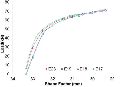
A series of tests using different speeds have been made to check how the speed parameter af-fects the hardening of the specimen. The ratios tested were 400 mm/min, 0.6 mm/min, 4 mm/ min and 60 mm/min.Fig 9shows the results of the tests E17-400-6-Al2030O-50x50x30, E18-0.6-6-Al2030O-50x50x30, E19-4-1.5-Al2030O-50x50x30-I and E23-60-6-Al2030O-50x50x30. It can be appreciated that the speed does not produce significant changes in the resulting stresses. The shape factor present in the plotted graphics corresponds toHT/L.
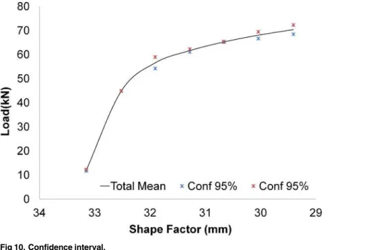
To support the null hypothesis, a statistical study was performed following the UNE 66040:2003 standard (ISO 2602:1980 equivalence),“Statistical interpretation of test results. Mean Estimation. Confidence interval”[22].Fig 10shows the confidence interval that results from comparing the tests performed at different speeds, being this confidence interval of 95%.
Fig 9. Efforts.Efforts obtained using different speeds.
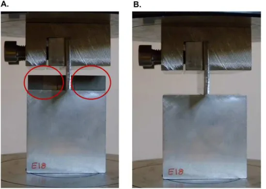
Fig 11displays the test performed on the work-piece E22 at a speed of 60 mm/min (Fig 11A) and a closer look to the indentation caused (Fig 11B). As can be seen, certain fragility in the ma-terial is appreciated. Cracks appear in the surface of the work-piece near the margins of the punch. This phenomenon may distort the results for a later comparison, justifying that deeper indentations are undesirable.
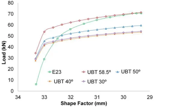
In Using the modular distribution studied during the application of the UBT, the optimal results are obtained for an angle ofθ= 58.5°. Therefore, the highest difference between the
re-sults obtained applying the analytical method and those obtained from the tests is reached at/ for the first values of the shape factor, as can be observed inFig 12. This first part of the graph relates to the first instants of the test. Once exceeded 1 mm in the indentation, the results begin to converge, showing a proper evolution thereof and a good performance of the model set.
Fig 10. Confidence interval.
doi:10.1371/journal.pone.0122790.g010
Fig 11. Indented sample.Indentation performed (A); and detail of the samples cracks (B).
Ultimately, to develop a comparative study between the tests conducted and the results ac-complished with the model of the UBT new modular distribution, a mean average for the test groups of 60 mm/min, and 4 mm/min is performed. This comparison is shown inFig 13. The UBT modular model follows the evolution of the stresses obtained in the indentation tests carried out.
Fig 12. Results.Results evolution depending on the angle for E23.
doi:10.1371/journal.pone.0122790.g012
Fig 13. Comparative between test and UBT model.
As the indentation gains depth, the difference between the developed analytical model and the results obtained with the experimental tests decreases. Taking into account that shallow in-dentations (1 or 2 mm) are not interesting from this study’s point of view, the first values of the graph can be disregarded. Hence, with a 2 mm indentation, the difference between the modular UBT model and the test at 4 mm/min and 60 mm/min are of 11.4% and 8.8% respectively. Thus, the deeper the indentation gets, the lower this difference is. Finally, at a 6 mm indenta-tion the differences are become 0.6% and 2.1%. These results are consistent with other studies that apply the UBT to different manufacturing processes and compare results with experimen-tation [23–27].
Conclusions
In this paper, the experimental validation analysis of the application of the Upper Bound Theo-rem in indentation by its new modular configuration is presented. This new configuration is based on modules of two Triangular Rigid Zones each. Indentation is considered to be included within the new processes that are been developed in the field of forging, such as the Incremen-tal Forming Processes.
Only the Infinite consideration of the model has been studied, since this is more related to indentation processes. Of the two configurations, the Infinite one is admitted as the general ap-plication. The Infinite configuration covers the range of work-pieces normally used in the manufacturing industry for forming processes such as indentation. The range of finite work-pieces resembles the deformation done by sheet metal forming processes, which are out of the scope of this study. In order to make a comparison of the results obtained with the new modu-lar model of the Upper Bound Theorem, a substantial number of indentation tests have been raised, assuming plane strain. Moreover, the influence that the strain rate has on the strain hardening parameter has been studied, having noticed that, for the different speeds studied, the results show similar values. Therefore, in the cases studied, the influence of the speed on the strain hardening effect can be rejected, due to the Infinite consideration of the work-piece.
Making the comparison between the mean values of the tests performed, for the different speeds considered, and the results obtained applying the new modular consideration of the Upper Bound Theorem, the similarity in the evolution of both analysis can be appreciated. There is a wide difference in the early stages of the deformation process (between 0 and 1 mm of penetration); however, the model tends to stabilize the results showing a progressively ap-proach to the real effort values. The optimal apap-proach is obtained with an angle of 58.5° for the selected modular model.
Thereby, a method that simplifies the existing methods for the study of the efforts needed in deformation is presented. On the one hand, from the mathematical perspective, the application of the Upper Bound Theorem under its modular configuration and after the model is properly developed, involves a less complicated implementation compared to other methods, such as the Finite Element Method. On the other hand, from the analytical perspective, the modular consideration simplifies the mathematical resolution of the problem, presenting a simpler final equation.
Similarly, its lower computational cost makes the new developed method appropriate to achieve the study of the efforts needed to carry out the relevant deformation. In addition, thanks to the versatility of the modular configuration exposed, the adaptation of the model to different dies geometries is possible.
Likewise, the inclusion of the different parameters that can be present in a deformation process, allows working with a model closer to reality.
Finally, with the developed method it is possible to establish the efforts curves of the defor-mation process. Thus, the upper limit necessary to ensure the defordefor-mation can be obtained.
Acknowledgments
The authors want to thanks the University of Malaga—Andalucia Tech Campus of Interna-tional Excellence, and the FPU program of the Ministry of Education, Culture and Sport of Spain for its contribution on this paper.
Author Contributions
Conceived and designed the experiments: CB FM LS. Performed the experiments: CB. Ana-lyzed the data: CB FM MJM LS. Wrote the paper: CB FM LS.
References
1. Chakrabarty J. Theory of Plasticity. U.K.: Elsevier Science; 2006.
2. Groche P, Fritsche D, Tekkaya EA, Allwood JM, Hirt G, Neugebauer R. Incremental Bulk Metal Form-ing. CIRP Ann-Manuf Technol. 2007; 56: 635–656.
3. Allwood JM, Utsunomiya H. A survey of flexible forming processes in Japan. Int J Mach Tools Manu. 2006; 46: 1939–1960.
4. Camacho AM, Marín MM, Rubio EM, Sebastian MA. Application of different simulation strategies for the analysis of Multi-Stroke Localised-Incremental Forming operations. Advances in Non Conventional Materials Processing Technologies. Mater Sci Forum. 2012; 713: 19–242.
5. Bernal C, Camacho AM, Marín M, de Agustina B. Methodology for the evaluation of 3D surface topogra-phy in Multiple Indentation Processes. Int J Adv Manuf Tech. 2013; 69: 2091–2098.
6. Jianming W, Feihong L, Feng Y, Gang Z. Shot peening simulation based on SPH method. The Int J Adv Manuf Tech. 2011; 56: 571–578.
7. Bernal C, Camacho AM, Arenas JM, Rubio EM. Analytical procedure for geometrical evaluation of flat surfaces formed by Multiple Indentation Processes. App Mech Mater. 2012; 217–219: 2351–2356.
8. Nowak J, Madej L, Grosman F, Pietrzyk M. Material flow analysis in the Incremetal Forging technology. Inter J Mater Form. 2010; 3: 931–934.
9. Hirt G, Kopp R, Hofmann O, Franzke M, Barton G. Implementing a high accuracy Multi-Mesh Method for incremental Bulk Metal Forming. CIRP Ann-Manuf Technol. 2007; 56: 313–316.
10. Alfozan A, Gunasekera JS. Design of profile Ring Rollin by Backward Simulation using Upper Bound Element Technique (UBET). J Manuf Process. 2002; 4: 97–108.
11. Bagudanch I, Garcia-Romeu ML, Ferrer I, Lupiañez J. The effect of process parameters on the energy consumption in Single Point Incremental Forming. Procedia Eng. 2013; 63: 346–353.
12. Topcu N. Numerical, analytical and experimental analysis of Indentation. Ph.D. Thesis, Turkish: Midlle East Technical University. 2005. Available: etd.lib.metu.edu.tr/upload/12605942/index.pdf
13. Martín F, Camacho AM, Domingo R, Sevilla L. Modular procedure to improve the application of the Upper-Bound Theorem in Forging. Mater Manuf Process. 2013; 28: 282–286.
14. Rubio EM, Domingo R, Arenas JM, González C. Energetic analysis of the drawing process by Upper-Bound Techniques. J Mater Process Tech. 2004;155–156: 1220–1226.
15. Martín F, Sevilla L, Sebastian Perez MA. Implementation of technological and geometrical parameters in forging processes by means of the Upper Bound Element Technique. AIP Conf Proc. 2009; 1181(1): 455–463.
16. Johnson W, Mellor PPB. Engineering Plasticity. Chichester: Ellis Horwood Limited; 1983.
17. UNE- EN 573–3. Aluminium and aluminium alloys—Chemical composition and form of wrought
prod-ucts. Part 1: Numerical designation system. Madrid. AENOR; 2005.
18. Rowe GW. An Introduction to the Principles of Metalworking. California: Edward Arnold Limited; 1971. 19. UNE-EN ISO 6892–1. Metallic materials—Tensile testing. Part 1: Method of test at room temperature
20. E 676-00. Standard Test Method for Tensile Strain-Hardening Exponents (n-Values) of Metallic Sheet Materials. West Conshohocken: ASTM International; 2007
21. Bermudo C, Martín F, Sevilla L. Analysis and selection of the modular block distribution in indentation process by the Upper Bound Theorem. Procedia Eng. 2013; 63:388–396.
22. UNE 66040. Statistical interpretation of test results. Estimation of the mean. Confidence interval. Ma-drid. AENOR; 2003.
23. Altinbalik T, Ayer O. Effect of die inlet geometry on extrusion of clover sections through curved dies: Upper Bound analysis and experimental verification. T Nonfer Metal Soc. 2013; 23: 1098–1107.
24. Hwang BC, Hong SJ, Bae WB. An UBET analysis of the non-axisymmetric extrusion/forging process. J Mater Process Tech. 2001; 111: 135–141.
25. Hwang BC, Lee HI, Bae WB. A UBET analysis of the non-axisymmetric combined extrusion process. J Mater Process Tech. 2003; 139: 547–552.
26. Parvizi A, Abrinia K. A two dimensional Upper Bound Analysis of the ring rolling process with experi-mental and FEM verifications. Int J Mech Sci. 2014; 79: 176–181.