small axial turbines
Sanda BUDEA*
,1, Mircea Dimitrie CAZACU
1*Corresponding author
*
,1“
POLITEHNICA
”
University of Bucharest, Faculty of Energetics,
Department of Hydraulics, Hydraulic Machinery and Environmental Protection
Spl. Independentei 313, Bucharest, 060402, Romania
[email protected]*, [email protected]
DOI: 10.13111/2066-8201.2013.5.3.2
Abstract: This paper continues research of the authors and presents some theoretical aspects regarding the maximum power extract from the wind turbines, the optimal incidence angle, the best twisting of the blade and experimental research done in the laboratory of Renewable Energy from the Hydraulics, Hydraulic Machineries and Environmental Engineering Department, on small axial turbines, with impeller of 500 mm and 2000 mm in 3 constructive variants: with 3, 4 and respectively 8 blades. These turbines can have applications both aerodynamic - wind turbines but also hydrodynamic.
It was determined the provided power, the starting / braking torque of the impeller and the power coefficients for these three type of turbines. From the experimental research resulted that the best behavior had the small impeller of 500 mm, with four bladed with cp = 0.56, tested in water, than the 500 mm impeller with three blades having the power coefficient cp = 0.43, tested in air and the last impeller, with 2000 mm and 8 bladed, has about cp = 0.4, tested in air too. These experimental results are the basis of various aerodynamic and hydrodynamic applications and further research.
Key Words: axial turbine, best incidence angle, power coefficient.
1. INTRODUCTION
This article presents some theoretical aspects regarding the maximum power extract from the axial turbines, the best incidence angle and the specific twisting of the blade. The article presents also the experimental research results in the study of the performances of three turbines with small dimensions, two of then with 500 mm diameter, with three and four blades, tested in water and also in air, and the third with 2000 mm diameter, with eight blades, tested in in air at different wind velocities. The studied axial turbines have the axis in horizontal position, being of HAWT (Horizontal-axis wind turbine) type.
To convert the kinetic energy of the fluid in maximum power we adopted aerodynamic profilated blades, which are offering the greatest extracted power and number of rotations, and consequently the smallest size for the turbine itself and for the electrical generator.
Starting from the theoretical results obtained from aerodynamic and hydrodynamic modeling and numerical analysis, three axial impellers, having the diameter of 0.5 m (two of them) and 2 m (the third), with the airfoil profile type Gottingen 450 were manufactured, inspired from similar studies [1-10].
Hydrodynamic and aerodynamic experimental cases for the small impeller with diameter of 0,5 m with 3 and 4 profilated blades were made. The best power coefficient of 0,56 was obtained in hydrodynamic tests with the impeller having 4 blades. For the case with 3 blades the power coefficient was found to be 0,43, tested in wind.
For the experimental study of the impeller with the diameter of 2 m and 8 blades, we considered only the aerodynamic behavior, as wind turbine. A power coefficient of about 0,4 was obtained. The experimental research results are detaliated below.
2. THEORETICAL APPROACH
2.1 Maximum power
For a hydraulic or wind turbine rotor very important is to extract a maximum mechanical power from the kinetic energy of the fluid stream, through the blades with a certain curvature and relative thickness, having the profiles set at the optimal incidence angle.
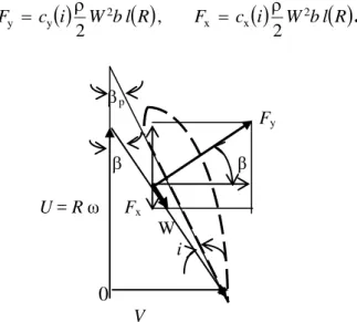
Corresponding to figure 1, the method [5-8] consists in considering a wing chord at the peripheral radius Rp of the blade at different incidence angles io wТtС rОspОМt to tСО β direction of relative velocity W and we shall consider the lift force perpendicularly of this direction, as well the drag force, which operates on the relative flow direction:
i W bl
R cF 2
y y
2
, F c
i W2bl
Rx x
2
.
(1)p
Fy
β
U = Rω
Fx W i
0
V
Fig. 1 Velocity triangle and the components of aerodynamic resultant
Projecting these two components of the hydrodynamic resultant on the turbine shaft direction, we shall obtain the axial force which loads the bearing:
cos sin
sin 2 sin
cos y x
2 2 x
y
a bl R c i c i
V F
F
F , (2)
We considered the relations V = W sin = U tg . For z blades, the total axial force will be:
R r
rc
i c
i
l b V z F
n
R
x y 1
2 2
total
a 1 10,89 3,3
2
We noted the blade section span by b, the profile depth by l (R) and the dimensionless radius by r = R/Rp.
For the best conversion of the kinetic energy of the fluid into maximal mechanical power at the turbine propeller, we shall cancel its partial derivative with respect to the relative angle .
This way, is obtained the optimum setting angle of the peripheral blade profile p = - i, for different profile shapes, at the incidence angles i, in order to obtain a maximum value in the scalar multiplication between the peripheral component of the resultant and the rotational velocity.
Projecting the two components of the aerodynamic resultant on the rotational peripheral direction, we obtained the mechanical power expression:
3 2 x 2 y 3 x y u sin cos sin cos 2 cossin F V bl c i c i
F U UF
P , (4)
The maximum power is obtained by cancelling the partial derivative:
4 2 x 3 2 y sin cos 2 cos sin cos 10 c i c i
P
, (5)
and applying the relation V = UtР β at tСО outskТrts, wО oЛtain the optimal angular velocity:
j j p p opt tg R U R V
, (6)
j opt j tg R
V →
j opt j j 1 V tg arc R R (7)
The power maximization was obtained only by the selection of the optimum incidence angle [4].
i c
i V bl
A
R c
i B
R c
i
c bl V i c i c R l b V V F R P x j y j 3 x j 3 j 2 y j 2 j 3 j 2 j x j y j j 2 j u j opt j 2 sin cos sin cos 2 sin cos sin 1 2 tg (8)The performances of aerodynamic and hydrodynamic profiles have been calculated and the maximum power and peripheral velocity was developed by the profile Gö 450 [9, 10] (table 1) for the incidence angle i = 3o.
Table no. 1
i
o cy cx cy/ cx βo βp,opt3
0.63 0.032 19.69 4.36 1.34o2.1 The best incidence angle and the twisting of the blade
0 4
4
2 y4
y1
y4 x1 opt
y4 x2 opt
3
c c R Vc
c R
Vc c i
i . (9)
In the table 2, tСО valuОs of tСО flow rОlatТvО anРlО β(R) and the optimum incidence angle i(R) for different radius of the impeller are presented [6-8].
Table no. 2 Channel Diameter
D (mm)
Relative flow angle
β (o )
Incidence angle ioptim(o)
Blade angle βp(
o )
Blade twisting δ(o)
1 500 16.9 11.5 5.3 0
2 400 20.7 12.2 8.6 3.3
3 300 26.8 12.8 14.0 8.7
4 200 37.2 13.4 23.8 18.4
5 100 56.6 14 42.6 37.3
The optimum incidence angle decreases with the increasing of the radius thus, allowing to obtain a greater velocity around the profile. The extracted mechanical power is proportional with its 3rd power, as in relation (9).
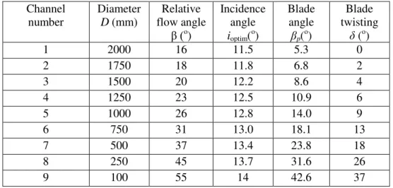
Applying a geometrical similarity criterion for the propeller having 2 m diameter, we obtained the values presented in table 3:
Table no. 3 Channel
number
Diameter D (mm)
Relative flow angle
β (o )
Incidence angle ioptim(o)
Blade angle
βp(
o )
Blade twisting
δ (o)
1 2000 16 11.5 5.3 0
2 1750 18 11.8 6.8 2
3 1500 20 12.2 8.6 4
4 1250 23 12.5 10.9 6
5 1000 26 12.8 14.0 9
6 750 31 13.0 18.1 13
7 500 37 13.4 23.8 18
8 250 45 13.7 31.6 26
9 100 55 14 42.6 37
Starting from the theoretical studies, 3 different impellers were manufactured:
- 500 mm diameter and 3 blades, tested in aerodynamic and hydrodynamic conditions; - 500 mm diameter and 4 blades, tested in aerodynamic and hydrodynamic conditions; - 2000 mm dimeter and 8 blades, tested in aerodynamic conditions – wind turbine.
3. EXPERIMENTAL RESEARCH
3.1 Axial turbine with propeller of 500 mm and three blades
three blades has a power coefficient of 0,43, tested in aerodynamic conditions since the hydrodynamic conditions has cp lesser[7, 11].
In figure 2 it can be observed the variation of the power coefficient and of the power generated by this axial turbine with the impeller of 500 mm diameter, having 3 blades.
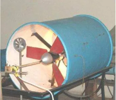
In figure 3 is presented the experimental facility with the wind tunnel and the anemometer for the air velocities.
Fig. 2 Aerodynamic tests of the propeller with 3 blades and 0,5 m diameter - Variation of the cp and P(W) with
the air flow velocities
3.2
Axial turbines with propeller of 500 mm and four blades
During the hydrodynamic tests with this type of impeller an enhanced performance was obtained, given the maximum power coefficient cp = 0.56, (see figure 4).
The experimental facility consisted in a open channel in
which was placed the rotor
and a hydrometric ratchet for measuring the water velocity.
Fig. 4 Hydrodynamic tests of the impeller with 4 blades and 0,5 m diameter - Variation of the cp and P(W) with
the water current velocity
For the same propeller, in aerodynamic experimental research the maximum value of the power coefficient was cp = 0.53, as displayed in figure 5.
Fig. 5 Aerodynamic tests of the propeller with 4 blades and 0,5 m diameter - Variation of the cp and P(W) with
3.3 Axial turbine with propeller of 2000 mm and eight blades
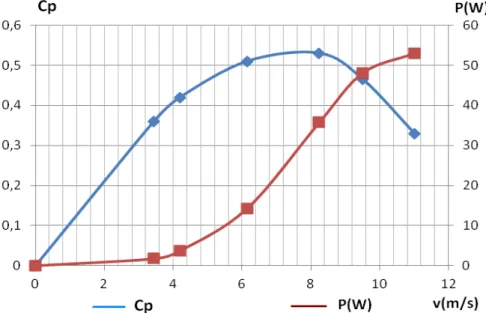
The power generated with this propeller and the corresponding power coefficients are given in figure 6.
Fig. 6 Power curve and power coefficient relative to the wind velocities for the impeller with 8 blades and diameter of 2m
Satisfactory results were obtained in this case as the power coefficient was about 0,4 and the power generated about 600 w a wind velocity of 11 m/s. the best aerodynamic behavior was found for wind velocities of 6-7 m/s.
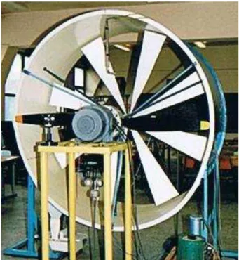
Figure 7 presents the wind tunnel for the aerodynamic tests with the propeller with 2 m diameter and eight profiled blades.
Geometrical similarly criterion and Reynolds and Froude similarly criterions were complied in these theoretical analysis and experimental studies.
4. CONCLUSIONS
Starting from the theoretical results obtained from aerodynamic modeling and numerical analysis, three axial impellers, with profiled blades type Gottingen 450 were manufactured. In order to extract the maximum power from the fluid, the theoretical analysis shows that the rotor should have an optimal angle of incidence of 3°. However it was revealed from our study that the optimal values of the angle of incidence are between 12 to 14°.
The propeller geometry had the blade pitch angle to the hub of 5 and the maximum blade twisting specify of 37.
Three different axial rotors with 500 mm diameter and 3 blades, 500 mm diameter and 4 blades and 2000 mm diameter and 8 blades were manufactured complying these features.
In the experimental research were obtained very good results for the impeller with 4-blades (cp = 0,56 tested in hydrodynamic conditions, at a water velocity of 0,6 m/s and cp=0.52 tested in aerodynamic conditions, at a wind velocity of 6-7 m/s. Also satisfactory results were obtained for the other two propellers.
Reynolds and Froude similarly criterions and geometrical similarly criterion were respected during these studies.
These experimental results represent the basis for future research on various aerodynamic and hydrodynamic applications.
REFERENCES
[1] . . Ща , О Г э , Э А , к а
-и а , 1955, 234-235.
[2] ***, Maши oМ o иО, Э o e e a o , Vol. 12, Mo к a, 1949, 208 - 210. [3] D. Pavel. MaşТnТ СТdraulТce. Vol.1, Energetics State Publ. House, Bucharest, 1954.
[4] M. D. Cazacu, A. CТoМсnОa, DetermТnarea ungСТuluТ de aşezare βoptimumpentru paletele turbinelor eoliene cu ax orizontal, Zilele HidraulicТТ ’98, Conf. WТnН EnРТnООrТnР, MaТ 1998, TОМСnТМal UnТvОrsТtв of CТvТl Engineering, Bucharest, 365 – 368.
[5] M. D. Cazacu, The maximization of the propulsion force for an aircraft or ship propeller, The 30-th Caius Iacob Conference Fluid Mechanics and its Technical Applications, Bucharest, 25-26 November 2005, CD Proceeding.
[6] M. D. Cazacu, Optimization of the axial propulsion force, The 31-th Caius Iacob Conference on Fluid Mecanics and its Technical Application, 19-21 oct. 2006, Buletin of Transilvania Univ. Brasov, Vol.13(48), serie B 1 – Mathematics, Informatics, Physics, 71-76.
[7] M. D. Cazacu, S. Nicolaie, Micro-Hydraulic turbine for run-of-river power station, Conferinta hidroenergeticienilor din Romania, Dorin Pavel 2002.
[8] S. Budea, M. D. Cazacu, Velocity spectrum in axial relative motion of wind turbine, CIEM 2011, ISSN 1454-23xx.
[9] ***, HüttО – Des Ingenieurs Taschenbuch I, 26. Auflage. Berlin, Verlag – von Wilhelm Ernst & Sohn, 407-408.
[10] ***, HüttО I –Manualul Inginerului, Publishing House AGIR, Bucharest, 1947, 510-511.