Annales
Geophysicae
Disturbance of plasma environment in the vicinity
of the Astrid-2 microsatellite
N. Ivchenko1, L. Facciolo1,2, P. A. Lindqvist1, P. Kekkonen3, and B. Holback4 1Alfv´en Laboratory, Royal Institute of Technology, Stockholm, Sweden
2Politecnico di Torino, C. so Duca degli Abruzzi, Torino, Italy 3Oulu University, Oulu, Finland
4Swedish Institute of Space Physics, Uppsala, Sweden
Received: 19 July 2000 – Revised: 20 November 2000 – Accepted: 15 December 2000
Abstract. The presence of a satellite disturbs the ambi-ent plasma. The charging of the spacecraft creates a sheath around it, and the motion of the satellite creates a wake dis-turbance. This modification of the plasma environment in-troduces difficulties in measuring electric fields and plasma densities using the probe technique. We present a study of the structure of the sheath and wake around the Astrid-2 microsatellite, as observed by the probes of the EMMA and LINDA instruments. Measurements with biased LINDA probes, as well as current sweeps on the EMMA probes, show a density enhancement upstream of the satellite and a plasma depletion behind the satellite. The electric field probes detect disturbances in the plasma potential on mag-netic field lines connected to the satellite.
Key words. Space plasma physics (spacecraft sheaths, wakes, charging; instruments and techniques)
1 Introduction
Satellites are widely used for in situ measurements in the ionosphere and the magnetosphere of the Earth. To make de-tailed measurements it is necessary to understand the distur-bances the instrument (in this case, the satellite itself) intro-duces in the studied system. A body in contact with a plasma usually becomes charged with respect to the plasma poten-tial. The charge is determined by the balance of currents both to and from the body, carried by plasma electrons and ions impinging on the body, and photoelectrons and secondary electrons emitted by the body itself. To achieve a current bal-ance, the potential distribution around the body is disturbed and thus, attracts or reflects particles of the corresponding charge. A body moving through a compressive medium dis-turbs the density and velocity distributions around it, forming a wake region behind it and a compression in front of it.
Among the basic measurement principles the Langmuir probe holds an important place. Used in the laboratory since
Correspondence to:N. Ivchenko ([email protected])
the 1920’s, it has also been applied successfully on satel-lites. The most common applications are the double probe technique for measuring electric fields (Fahleson, 1967), bi-ased Langmuir probes for density measurements (e.g. Eriks-son and Bostr¨om, 1995), and current/voltage swept probes for determining plasma parameters (Fahleson et al., 1974). Ideally, one would like to expose the probes to the undis-turbed plasma, but in reality, the plasma is disundis-turbed by the satellite to which the probes are attached by means of wire booms. The probes are kept away from the satellite by the centrifugal force due to the satellite spin.
Studies of the interaction of the spacecraft with the space plasma environment have been conducted both for practical and fundamental reasons since the beginning of the space age. A recent review by Hastings (1995) gives an idea of the relative amount of research done on various aspects of the spacecraft-plasma interaction. The most direct phenomenon to study is the formation of the wake (Al’pert et al., 1965; Kasha, 1969). Several in situ measurements have been re-ported (e.g. Samir and Jew, 1972), and compared with differ-ent theories (Samir and Fontheim, 1981; Samir et al., 1989). Another important subject of research is that of spacecraft charging (Garrett, 1985) which, in extreme cases, may lead to dramatic effects on the spacecraft instrumentation. The advent of the Space Shuttle opened possibilities to study the environment of larger bodies in orbit (Murphy et al., 1989). Other recent studies have addressed current collection by highly charged spacecrafts (Neubert et al., 1990), an impor-tant question for the understanding of the charging of bodies in the wake of larger spacecraft and electrodynamics of teth-ered systems (Dobrowolny and Melchioni, 1993). There has been surprisingly little work done on understanding the in-fluence of the satellite-related disturbances on the measure-ments with Langmuir probes in space plasmas.
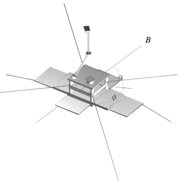
Fig. 1. Schematics of the Astrid-2 microsatellite. LINDA probes are mounted at the stiff booms protruding from the solar panel edges, with proben1 on the right side of the figure. The EMMA probes (not shown) are placed at the ends of the wire booms, and numbered clockwise, starting with probe 1 in the top of the figure.α
is the angle between the magnetic field and the spin plane, and spin phaseφis measured between the direction of probe 3 and projection of the magnetic field in the spin plane.
probe current on the angle to the magnetic field. On Viking altitudes, the densities are low and photoelectrons play a significant role (Hilgers and Holback, 1993). A theory de-scribing the dynamics of ambient electrons and photoelec-trons was developed by Hilgers (1995). Disturbances of the electric field measurements due to the gradients of the background plasma density were discussed by Laakso et al. (1995). Chust et al. (1998) addressed the question of the anomalously strong electric field parallel to the magnetic field, which is occasionally measured on Freja, and demon-strated that it was not related to either particle shadowing or density gradients. They were not able to exclude other mech-anisms that could have produced similar artefacts.
The purpose of this work is to study the plasma environ-ment of the Astrid-2 microsatellite by means of two Lang-muir probe instruments onboard – the EMMA and LINDA instruments. Astrid-2 (see Fig. 1) was launched on 11 De-cember 1998 into a 83◦declination circular orbit at 1000 km altitude and was operational until the end of July 1999. As the LINDA instrument is described in detail elsewhere in this issue we will present here only their most important charac-teristics. The EMMA instrument for measuring the electric field consists of four identical spherical probes (40 mm in diameter) placed 3.3 m away from the satellite center at the tips of wire booms. The satellite was spin-stabilized, with the spin period around 7 seconds, and spin axis oriented
to-tre of the satellite. The LINDA probes were biased positive (Ubias = +10 V) relative to the satellite, and thus, should collect electrons effectively, with the value of the current be-ing proportional to the electron density. The collected current also weakly depends on the electron temperature, which is normally assumed constant when interpreting the data. The surface of one of the LINDA probes -n1 - was probably con-taminated during launch, and only the measurements from the other probe -n2 - will be used here.
This paper proceeds as follows. First, we describe the ge-ometry of the measurements, including the satellite configu-ration with respect to the orbital plane and the ambient mag-netic field. Later we present several cases for which three types of measurements were conducted – the EMMA probe potentials, current sweeps on one of the EMMA probes and LINDA continuous current measurements. The results are discussed and summarized in the last section.
2 Geometry of the measurements
The configuration of the Astrid-2 satellite means that mea-surements are possible only in the spin plane, at a constant distance from the satellite determined by the boom length. The disturbances of the plasma environment can only be de-tected if the plasma parameters at a probe location change with the spin phase, i.e. any symmetric sheaths or those ro-tating together with the satellite cannot be studied in-flight.
The geometry is, however, complicated. The satellite shape is far from being spherically symmetric. There are at least three externally imposed directions which are expected to break the symmetry of the sheath: the magnetic field, the spacecraft velocity and the direction towards the Sun. The ambient magnetic fieldBwill affect the motion of the plasma
Fig. 2.An example of a multiple EMMA sweep. The upper panel presents the bias current versus sample number, going down and up between−0.2 and 0.4µA twice; the lower panel shows the mea-sured probe potentials for the same samples. Sampling frequency was 2048 Hz, 5 samples with each bias current value were taken.
current collected by the satellite will be determined by the projected area transverse tov. Finally, the illumination by
the Sun creates an asymmetry in the photoelectron emission. The last aspect is probably the least important, as the As-trid-2 spin axis was kept within 30◦ around the Sun’s di-rection, in order to keep the solar panels illuminated. This means that the EMMA and LINDA probes in the spin plane were never shadowed by the satellite body. ThevandB
ori-entations change during the course of orbital motion. The or-bital plane and the spin plane of the satellite normally were not parallel. Thus, v lies in the spin plane twice per orbit, mostly at low latitudes. In some cases, when the angle be-tween the two planes is small (when the orbit goes in the dusk-dawn direction),v may be close to the spin plane all
the time. The ambient magnetic fieldBis almost identical to
the Earth’s intrinsic magnetic field, which is close to dipolar. Therefore,Bis in the spin plane four times per orbit – twice
at low latitudes and twice at high latitudes, in the opposite hemispheres.
We can expect to detect the effects of the complex sheath of the satellite on the available probes only for specific rel-ative orientations ofvandB. At low latitudes, the satellite travels almost along the magnetic field lines and both thev
andB directions are typically close to the plane where the
probe measurements are done. At high latitudes, the angles betweenvandB, andvand the spin plane are determined by
the orbital plane orientation, the tilt of the Earth’s magnetic dipole axis and direction of the satellite spin axis. We also expect the sheath size and structure to depend on the plasma parameters, such as density and temperature.
At any single time the measured quantities are only four EMMA probe potentials and two currents collected by the LINDA probes. However, by combining the measurements from a spin period, a one dimensional characteristic along the probe trajectory around the satellite (as a function of spin
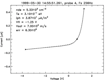
Fig. 3. An example of current sweep on an EMMA probe with a theoretical curve fitted to it. Solid curve - measured data, dashed curve - theoretical dependence (see text).
phaseφ) can be obtained, assuming the controlling param-eters (plasma density and temperature) do not change much during the spin period. Using the changes of the orientation ofBandvwith respect to the spin plane, one may obtain a two dimensional cut through the sheath structure by a sphere with a radius equal to the probe distance from the satellite centre. This assumes the plasma parameters to be constant throughout the whole interval needed to cover the ranges of interest in both the spin phase, and the angle between the spin plane and the magnetic field.
3 Multi-instrument measurements of disturbances of the plasma environment
The EMMA instrument operates the plasma probes in the high impedance mode, i.e. the potentialsViof the four probes relative to the satellite are measured for a set bias current
Vi =φi−φsat (1)
where φi is the potential of thei-th probe, andφsat is the satellite potential. The potential of each probe depends on its environment
φi =φpl+δφi(Ibias, n, T , ...) (2) whereφpl = −E·ri is the local plasma potential relative to the satellite location due to the presence of electric field
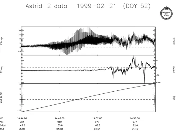
Fig. 4. Spurious electric fields observed when the magnetic field lies in the satellite spin plane. Panels from top to bottom show the components of the measured electric field in the spin plane most parallel and perpendicular to the ambient magnetic field, and the angle between the magnetic field and the spin plane.
as possible, and fed with a positive bias current to keep the probes close to the plasma potential. By taking the difference of the potentials of opposite probes, the potential drop in the plasma is estimated:
1Vij =Vi−Vj =φi−φj (3)
and by dividing it by the distance between the probes, the electric field is obtained. Due to the motion of the satellite across the geomagnetic field lines, an induced electric field
E=v×Bis set up in the satellite reference frame. This field can be as large as 350 mV/m for low altitude ionospheric satellites, such as Astrid-2 and thus, is often the main con-tribution to the measured electric field. In order to study the physically interesting electric fields, it is subtracted from the measurements.
The presence of the satellite may disturb both the potential distribution in the plasma and the properties of the plasma it-self (density and temperature), which determineδφi(Ibias, n,
T , ...). The changes in plasma parameters may be different at the locations of different probes. Thus, subtracting the sig-nals from the opposite probes will introduce a non-cancelled term ofδφi −δφj into (3), leading to a spurious contribu-tion to the signal unrelated to the ambient electric field. A known example is the spurious parallel electric field as seen when the probes pass the magnetic field lines connected to the satellite (see Fig. 4). When the angle betweenBand the spin plane crosses zero, a “hedgehog” of spikes in the
elec-tric field component parallel tobis observed. This effect will
be discussed later in the paper.
To analyze the disturbances related to the complex sheath of the satellite, the differential probe signal is taken to get rid of variations of the spacecraft potential. The plasma en-vironment is expected to be disturbed in limited ranges of angles around specific directions of the probe booms (e.g. spin phases when the booms are aligned withBorv). Thus,
it is more convenient to take the difference of the adjacent probe potentials, e.g. V12 = V1−V2, shifting the distur-bances by 90◦in the spin phase. (Probes 1 and 3 are both in the disturbed regions for the same spin phase).
TheV12signal is a sine with an amplitude determined by the contributions due tov×B, and any geophysical electric field that may exist in the ionosphere. In addition, satellite-related disturbances appear for the specific spin phase inter-vals. It is found that the strongest disturbances are seen when a probe is close to the magnetic field lines connected to the satellite body. To concentrate on the latter signal, we sub-tract a sine fit to the data, with a period equal to the spin period. Only spin phase intervals, where no probe is within 15◦from the magnetic field direction, are used in the fitting. The residual may be interpreted asδφi.
and potential relative to the plasma
In2=I (φn2, n, T , ...) . (4)
While the probe potential is kept constant atUbias= +10V relative to the satellite (in the reference frame moving with the satellite), it varies relative to the plasma
φn2=φsat+rn2·(v×B)+Ubias (5) whereφn2is the potential of the LINDA proben2 relative to the plasma at the location of the probe,φsatis the potential of the satellite relative to the plasma at the satellite’s location, andrn2is the position of the probe relative to the satellite.
The assumption normally made in order to relate the LINDA current In2 to the plasma density is that bothφsat and the
v×B contribution are much smaller than Ubias, and φn2 does not change much with respect to the plasma. In many cases, this is valid, as will be shown for specific cases. The variations ofIn2 are then related to the plasma parameters. For a Maxwellian plasma, the dependence on the density is linear, while the temperature dependence is proportional to the square root. Thus, it is a good approximation to assume most of the time that the temperature is constant, and the collected current is a measure of the electron density.
Disturbances of the EMMA probe potentials are difficult to unambiguously relate to the plasma parameter changes. Interpretation of the LINDA probe current as being propor-tional to the electron density is based on assumptions of iso-tropic plasma at constant temperature. The plasma in the complex sheath of a satellite may be anisotropic and non-Maxwellian. The most complete information to be obtained with the probe measurements is the current-voltage charac-teristics of the probe in plasma; but even then, one has to re-sort to models describing the current collection by the probe. The EMMA electric field instrument was equipped with a sweep function, which allowed one to switch the bias current to a probe, according to a table uploaded from the ground. The maximum sweeping rate was 4 sweeps/second. How-ever, by making the bias current go up and down several times in the sweep table, multiple physical sweeps within one logical sweep could be carried out (see Fig. 2), thus making it possible to determine the plasma current-voltage characteristics at multiple occasions during the spin period. While representing the most interesting mode for studying the satellite sheath, this mode required extra commanding of the satellite and used much of the on-board memory (it re-quires sampling the probe potentials at the 2048 samples/s, which fills the memory in 4.5 minutes), and disturbed the electric field measurements by taking one of the probes out of the four-probe configuration. This special mode has been commanded on several occasions in June and July 1999.
A sweep analysis tool was developed to automatically fit a theoretical current-voltage curve to the measured sweep (see Fig. 3). In the simplest model (e.g. Lindqvist et al., 1994) the current to a probe can be written as
Ibias=4π r2nee s
kTe 2π me
1+ eV
kTe
−π r2iphe−eV / kTph(6)
for a positive probe and
Ibias=4π r2nee s
kTe 2π me
eeV / kTe−π r2i
ph (7)
−4π r2nee s
kTi 2π mi
+v 2 sat 16
1− eV
8mi kTi
2π mi +v
2 sat 16
−1
for a negative probe, where r is the probe radius, V is the potential of the probe relative to the plasma,vsat is the ve-locity of the satellite,iphis the photoemissivity,kTphis the energy of photoelectrons, and the rest of the notations have their usual meaning. The equations are valid for an unmag-netised Maxwellian plasma streaming with a velocity vsat relative to the probe. As the potentials are measured rela-tive to the satellite, a “floating” (satellite) potential should be introduced
Vi =V +Vf l. (8)
The tool attempts to fit the theoretical curve by finding ap-proximations for photoelectron currentiph, electron density
ne, electron temperature Te and floating potential Vf l, and assuming nominal or typical values for the rest of the param-eters. The complex relationship between the plasma parame-ters and the shape of the theoretical curve makes it difficult to use any standard fitting algorithms based on the least squares fit.
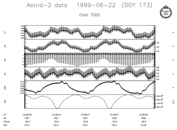
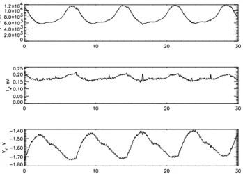
The algorithm used consists of the selection of four fixed points on the sweep curve, two on each of the two more or less straight parts, and an iterative loop which tries to fit the curve at these points. There are separate fitting functions for each of the four plasma parameters. One of them has an it-erative loop in itself, others just take one itit-erative step each time the function is called from the main loop. At the end of the main loop, there is a call to a function that checks if the chosen fitting accuracy is achieved. If not, the loop continues until the counters reach maximum values and the algorithm gives up. After the end of the loop, a least squares error is calculated for all the datapoints. If the error value is small enough, the fitting is further improved in another func-tion which calculates the least squares errors for all combi-nations of parameters plus/minus some predetermined delta. The combination resulting in the smallest error is chosen and this is repeated six times, bisecting deltas when needed. 3.1 Case 1: Motion quasiparallel to the magnetic field Figure 5 presents the potentials of the EMMA probes, the potential difference between probes 2 and 4, the LINDA cur-rent to a Langmuir probe and the angle between the magnetic field and the spin plane for 3 minutes on 22 June 1999. The satellite was travelling at low latitude. Due to the high in-clination of the orbit, the satellite moved essentially in the north-south direction, with the velocity being close to the di-rection of the magnetic field. In this case, the angle between
Fig. 5. EMMA measurements on 22 June 1999. Panels from top to bottom: potentials of probes 1 to 4 relative to the satellite, potential difference between probe 2 and probe 4, current collected by the LINDA probe, and angleαbetweenBand the spin plane. Note the different scale in panel 3.
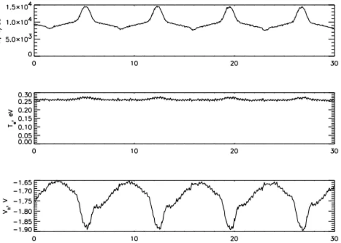
Fig. 7.Plasma parameters derived from the fits to the EMMA cur-rent sweeps for case 1. Panels from top to bottom: electron density, electron temperature and floating potential. Time interval of 30 sec-onds spans four spin periods.
The EMMA instrument was operated in the sweep mode from 12:39 to 12:41 UT. Current sweeps on probe 3 are visi-ble, as fast changes of the potential of that probe (see Fig. 6). It should be noted here, that the potential of the satellite itself is governed by a similar balance of currents as the potential of the probes. Changing the bias current to one of the probes requires modification ofφsat to adjust the currents collected from the plasma in order to obtain a new balance. These changes of the satellite potential are seen in theV1,V2 and V4signals, although the potentials of these probes are not af-fected by sweeping probe 3. The same effect is seen later at 12:41:30 UT, as a voltage sweep is carried out on the LINDA probes; all theVi signals show synchronous variations.
The differential signalV24 = V2−V4is not affected by the sweeping and shows a quasi-sinusoidal oscillation of in-creasing amplitude, mainly caused by thev×Bcontribution. Due to the motion almost parallel to the magnetic field, this contribution is rather small. A closer inspection of the data on a smaller time scale reveals periodic irregularities inV24. The LINDA probe current shows a spin phase dependence, as does the lower envelope of the probe 3 potential during the sweeps. Figure 7 presents plasma parameters obtained from the fits of the sweeps. The periodic variations of the estimated plasma density are evident, together withVf l vari-ations and somewhat smaller temperature changes.
To understand the relation of the disturbances to the direc-tions ofBandv, it is convenient to plot them in(φ, α) coor-dinates, whereφis the spin phase measured from the position when probe 3 is aligned with the projection ofBon the spin
plane, andαis the angle betweenBand the spin plane. The
direction ofvchanges somewhat during the interval, and can
be described by two angles: an angleαv between the spin plane and thevdirection, andφv, the angle between the pro-jections ofvandB in the spin plane. Figure 8 presents the plasma parameters derived from the sweep fitting in(φ, α)
coordinates.
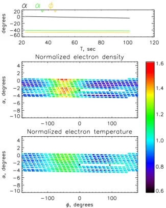
Fig. 8.“Maps” of plasma parameters in the vicinity of the Astrid-2 satellite, derived from the sweep measurements between 12:39 and 12:41 UT. The upper panel presents variation of the angle between Band the spin planeαduring the period when the sweep data were taken, the angle betweenvand the spin planeαv, and the angle between the projections ofBandvin the spin planeφv. Two panels below show normalized electron density and electron temperature as functions of spin phaseφandα.
The estimated electron density lies between 8000 and 14000 cm−3, and the temperature around 0.25 eV. These are rather typical values for Astrid-2 alititudes. The density cor-responds to the Debye length of 3 to 4 cm, which is much less then the scale size of the satellite. The changes of the derived electron density are systematic and are almost a factor of two in the course of a spin period. Increase in the plasma density is observed for the angles when the swept probe is upstream of the satellite, and a narrower and more shallow density de-pletion is seen in the direction antiparallel tov. A small
tem-perature increase is coincident with the density increase, and probably indicates some heating in the ram. The floating po-tential shows a harmonic variation due tov×B, a dip related to the density increase in the ram and some smaller irregu-larities at spin phases corresponding to the direction of the wake.
The sixth panel in Fig. 5 shows the current collected by probe 2 of the LINDA instrument, which is also plotted in
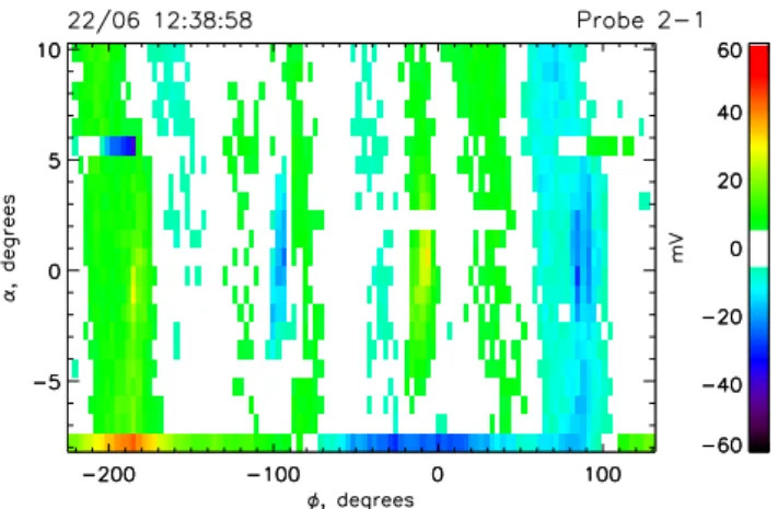
assump-Fig. 9.Map of the current collected by LINDA proben2 (normal-ized) in(φ, α)coordinates. In this figureφ = 0◦corresponds to LINDAn2 probe boom being parallel toB.
tion of constant bias potential relative to the plasma is valid. No absolute calibration is used here to relate probe current to plasma density. In this figure the most prominent feature is the current decrease in the wake region aroundφ= −180◦. The compression in the ram region is no longer symmetric as it was for the EMMA probe, but rather shows two broad maxima, with the leading one being somewhat higher (see also Fig. 5). Surprisingly enough, the direction of the ram proper corresponds rather to the local minimum. Another unexpected result is that the total range of the variation of the current to the probe is smaller than that of the density es-timates from the sweeps on EMMA probes (located further from the satellite), while the ram compression is expected to be decreasing away from the body.
A(φ, α)map of the distribution of the EMMA probe dif-ferential potentialV12with a sine fit subtracted is presented in Fig. 10. Four regions of disturbed potential are clearly visible: at 0◦, 90◦,−180◦and−90◦. The region at 0◦ cor-responds to the probe 1 boom being antiparallel toB, and at
−180◦along the magnetic field. The probe 2 boom is paral-lel to the magnetic field at 90◦. Note that a positive poten-tial disturbance seen on probe 1 givesV1−V2 >0, and on probe 2, givesV1−V2<0. The changes of the potential are mainly positive. The disturbance in the ram of the satellite (vis approximately alongB) is broader, and less structured. The disturbance in the wake of the satellite is rather
local-Fig. 10.Map of the disturbances of the potentials of EMMA probes 1 and 2 given asV1−V2in(φ, α)coordinates. Probe 1 is parallel toBatφ= −180◦, and probe 2 is parallel toBatφ=90◦.
ized to about 15◦–20◦around the direction of−B(a similar localized disturbance seems to be present even in the ram di-rection, masked by the broader maximum described). The amplitudes of the potential disturbances are of the order of several tens of mV.
3.2 Case 2: Motion oblique to the magnetic field
Figure 11 presents the EMMA and LINDA data collected at 15:23:00 to 15:27:00 UT on 29 June 1999. As in case 1, the satellite was travelling at low latitudes and the velocity was close to the spin plane. The angle betweenvandBchanged
from 156◦to 136◦in the course of the interval, i.e. velocity was oblique to the magnetic field.
The results of the sweep fitting are presented in Fig. 12. The estimated density is about half the density for the interval considered in the first case. Figure 13 shows(φ, α)the map of variations of plasma parameters derived from the sweep measurements. The total change in density during the spin is also about a factor of two, as in the first case. The shape of the changes is, however, somewhat different from the pre-vious case. The density increase in the ram is broader and covers almost half of the spin period, while the wake region hardly shows any depression at all and is less symmetric with respect to theBdirection, as compared to the first case. The
temperature shows larger variations, also lacking a symme-try with respect toB. The variations inVf lare dominated by thev×Bvariation, as the angle betweenvandBis larger
in this case.
LINDA current is more difficult to analyze in this case, as thev×Bcontribution is larger than in the first case. We note,
Fig. 11.EMMA measurements on 29 June 1999. The format is the same as in Fig. 5.
Fig. 12. Plasma parameters derived from the fits to the EMMA current sweeps for Case 2. The format is the same as in Fig. 7.
3.3 Case 3: Motion quasi-perpendicular to the magnetic field
The third case we present corresponds to the satellite moving at high latitudes. EMMA and LINDA data from 12:22:00 to 12:24:00 UT on 24 June 1999 are presented in Fig. 14. The angle betweenvandBchanged from 92◦to 94◦in the interval, with the velocity making an angle of 40◦ to the
Fig. 14.EMMA measurements for Case 3. The format is the same as in Fig. 5.
Fig. 15.Map of plasma parameters in(φ, α)coordinates for Case 3. The format is the same as in Fig. 8.
spin plane. The region is characterized by a rather disturbed density and largerv×Bvariations. This makes analysis of
the LINDA current data less straightforward, but systematic variations with several local minima and maxima during the spin period are clearly seen in the figure.
Figure 15 presents a(φ, α)map of the sweep-derived plas-ma parameters. A compression in the ram region is seen again, although the velocity vector is quite far away from the spin plane.
3.4 Cases 4 and 5: Disturbances in the probe potentials In the following two cases, no sweep measurements were made by the EMMA instrument. On the other hand, the dis-turbances of the electric field probe potentials are very typ-ical here. A large number of cases, where only continuous EMMA measurements in normal mode were available, was analyzed by Facciolo (2000).
Figure 16 presents the(φ, α)map of the disturbance in the differential potentialV12observed at around 00:56 UT on 14 March 1999. The satellite was travelling at low latitudes, i.e. the case is similar to case 1. ThevandBdirections are
Fig. 16.(φ, α)map of disturbances in the EMMA probes potentials fo Case 4. Broad smooth increases are evident at−180◦when probe 1 is ahead of the satellite, and at 90◦, when probe 2 is ahead of the satellite. In the regions behind the satellite, narrower and more structured increases are seen at 0◦and−90◦, respectively.
−180◦(in the ram region). The shape of the former distur-bance is similar to the satellite shape seen in perspective from the location of the probes; the part narrow inφextends long in the positiveαdirection, corresponding to the stiff boom, and the part broader inφ, is localized within several degrees of zero inα, corresponding to the satellite body and solar panel (compare to Fig. 1).
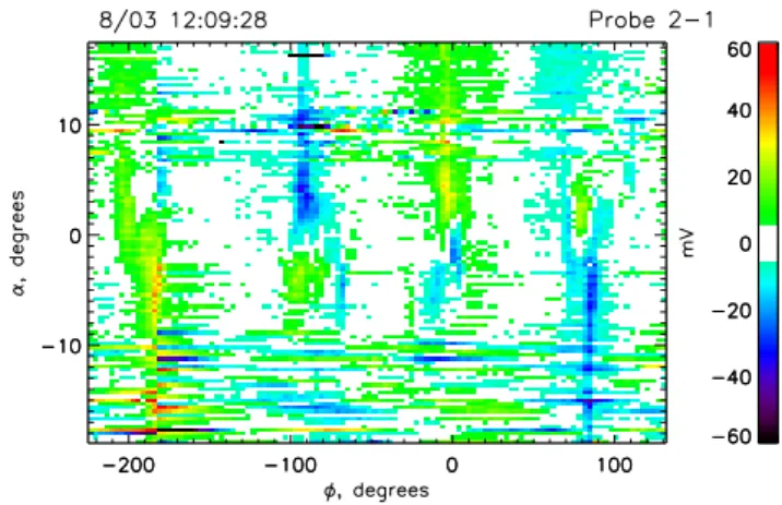
Figure 17 presents the (φ, α) map of the disturbance at around 12:10 UT on 8 March 1999. The satellite was trav-elling at high latitudes, with the velocity being almost per-pendicular to the spin plane. The potentialV12here is quite disturbed due to the presence of auroral electric fields, which is visible as noise in the map. The triangle-shaped distur-bance of the potential is recognized again, although this time, it is observed on both occasions when a probe is close to the magnetic field line crossing the satellite. The signatures at 0◦and−180◦are almost mirror images of each other, as are disurbances at 90◦ and−90◦. As the velocity vector is far from the spin plane, we do not expect to see any signatures of wake or ram, so the disturbance must be solely related to the sheath or presheath of the satellite, extending along the magnetic field lines.
4 Discussion and summary
A study of disturbances of the plasma environment by the Astrid-2 microsatellite is presented. The presence of the satel-lite modifies plasma parameters. These disturbances can be detected by the onboard probes, and thus, lower the quality of the measurements if not treated properly. The complicated geometry of the system makes it difficult to correct for the sheath and wake effects.
The motion of the satellite is supersonic relative to the ion thermal velocity. Plasma is compressed in front of the satel-lite and a wake (rarefaction) forms behind it. The change in plasma density depends on the distance from the satellite
Fig. 17. (φ, α) map of disturbances in the EMMA probes po-tentials for Case 5. Potential disturbances related to the electric field changes on timescales below the spin period are seen as noise throughout the figure. Structured disturbances in probe potentials are evident when the probes are close to the magnetic field direc-tion.
body. An estimate of plasma density, derived from analyz-ing current sweeps from the EMMA probes located at 3.3 m from the satellite center, shows a compression of several tens of percent extending over tens of degrees around the satellite velocity direction, and a smaller density depression some-times observed in the wake. The density derived from the LINDA probe (1.4 m from the satellite center) current mea-surements shows a different picture. A compression is also observed, but it is more structured, having broad local max-ima not necessarily in the ram direction. A rather narrow wake region is found behind the spacecraft. However, the to-tal range of variation of the electron density estimated at the EMMA probe locations (a factor of 2) is larger than the range of LINDA current variation (about 60%). The compression in the ram direction dominates the EMMA sweep measure-ments, while the depletion the wake is clearly visible in the LINDA data.
current to a biased probe was caused by various regimes for collecting both the photoelectrons from the satellite, which were escaping along the magnetic field, and the plasma elec-trons. For small background densities, the dynamics of the photoelectrons from the satellite become very important, si-multaneously as the Debye length becomes comparable to the scale size of the satellites. A common point is that the magnetic field seems to be important even for the Astrid-2 satellite.
In the electric field measurements, the effects of the psheath are more obvious. When a probe enters plasma re-gions connected by magnetic field lines to the satellite, its potential is changed by tens of mV. As the satellite shape is not symmetric with respect to the magnetic field, this leads to the detection of spurious electric fields parallel toB with
amplitudes of up to tens of mV/m. An example of this is presented in Fig. 4, and another possible example from the Freja satellite on similar altitudes was reported in Fig. 4 of Chust et al. (1998). This points out the intrinsic difficulties in measuring the parallel electric field by the double probe method. The parallel electric field measurements can be fur-ther affected by shadowing of directed particle fluxes by the satellite body, e.g. for measurements in auroral arcs. This question was not addressed in this study and only cases with-out significant particle precipitation were studied. In the case of extremely low densities or satellite charging, the sheath of the satellite may extend beyond the probes, producing even larger potential disturbances than the ones reported in this paper.
Acknowledgement. Topical Editor G. Chanteur thanks two referees for their help in evaluating this paper.
References
Al’pert, Yu. L., Gurevich, A. V., and Pitaevskii, L. P., Space Physics with Artificial satellites, Consultants bureau, New York, 1965. Chust, T., Louarn, P., Volwerk, M., de Feraudy, H., and Roux, A.,
Electric fields with a large parallel component observed by the Freja spacecraft: Artifacts or real signals? J. Geophys. Res., 103, 215–224, 1998.
temperature and density measurements by means of spherical double probes, Planet. Space Sci., 22, 41–66, 1974.
Garrett, H. B., The charging of spacecraft surfaces, in Handbook of geophysics and the space environment, ed. A. S. Jursa, US Air Force, 1985.
Hastings, D. E., A review of plasma interactions with spacecraft in low Earth orbit, J. Geophys. Res., 100, 14457–14483, 1995. Hilgers, A., Holback, B., Holmgren, G., and Bostr¨om, R., Probe
measurements of low plasma densities with applications to the auroral acceleration region and auroral kilometric radiation sources, J. Geophys. Res., 97, 8631–8641, 1992.
Hilgers, A. and Holback, B., Some aspects of satellite spin effects on sperical probe measurements in a magnetized plasma, Geo-phys. Res. Lett., 20, 347–350, 1993.
Hilgers, A., Interaction between biased sunlit electron collectors in an infinite-Debye-length magnetoplasma: Electron temperature threshold effect, J. Geophys. Res., 100, 5705–5713, 1995. Holback, B., Jacks´en, ˚A., ˚Ahl´en, L., Jansson, S.-E., Eriksson, A.
I., Wahlund, J.-E., Carozzi, T., and Bergamn, J., LINDA - the Astrid-2 Langmuir Probe Instrument. Ann. Geophysicae, 19, 601–610, 2001 (this issue).
Kasha, M. A., The ionosphere and its interaction with satellites, Gordon and Breach, New York, 1969.
Laakso, H., Aggson, T. L., and Pfaff Jr, R. F., Plasma gradient ef-fects on double-probe measurements in the magnetosphere, Ann. Geophysicae, 13, 130, 1995.
Lindqvist, P.-A., Marklund, G. T., and Blomberg, L. G., Plasma characteristics determined by the Freja electric field instrument, Space Sci. Rev., 70, 593–602, 1994.
Murphy, G. B. et al., The plasma wake of the Shuttle orbiter, J. Geophys. Res., 94, 6866–6872, 1989.
Neubert, T. et al., The sheath structure around a negatively charged rocket payload, J. Geophys. Res., 95, 6155–6165, 1990. Samir, U. and Jew, H., Comparison of theory with experiment for
electron density distribution in the near wake of an ionospheric satellite, J. Geophys. Res., 77, 6819–6827, 1972.
Samir, U. and Fontheim, E. G., Comparison of theory and in situ observations for electron and ion distributions in the near wake of the Explorer 31 and AE-C satellites. Planet. Space Sci., 29, 975–987, 1981.