ABSTRACT
http://dx.doi.org/10.1590/1678-775720150081
Effect of software version and parameter settings
on the marginal and internal adaptation of crowns
fabricated with the CAD/CAM system
Ji Suk SHIM1, Jin Sook LEE3,Jeong Yol LEE2, Yeon Jo CHOI3, Sang Wan SHIN2, Jae Jun RYU3
1- Korea University Ansan Hospital, Department of Prosthodontics, Gyeonggi-do, Republic of Korea. 2- Korea University Guro Hospital, Department of Prosthodontics, Seoul, Republic of Korea. 3- Korea University Anam Hospital, Department of Prosthodontics, Seoul, Republic of Korea.
Corresponding address: Jae Jun Ryu - Department of Advanced Prosthodontics, Korea University Anam Hospital - 73, Inchon-ro - Seongbuk-gu - Seoul - 136-705 - Republic of Korea - Phone: +82-2-920-5423 - Fax: +82-2-866-1499 - e-mail: [email protected]
6XEPLWWHG0DUFK0RGL¿FDWLRQ-XQH$FFHSWHG-XO\
O
bjective: This study investigated the marginal and internal adaptation of individual dental crowns fabricated using a CAD/CAM system (Sirona’s BlueCam), also evaluating the effect of the software version used, and the speci¿c parameter settings in the adaptation of crowns. Material and Methods: Forty digital impressions of a master model previously prepared were acquired using an intraoral scanner and divided into four groups based on the software version and on the spacer settings used. The versions 3.8 and 4.2 of the software were used, and the spacer parameter was set at either 4 Njm or 8 Njm. The marginal and internal ¿t of the crowns were measured using the replica technique, which uses a low viscosity silicone material that simulates the thickness of the cement layer. The data were analyzed using a Friedman two-way analysis of variance (ANOVA) and paired t-tests with signi¿cance level set at p.. 5esults: The two-way ANOVA analysis showed the software version (p.) and the spacer parameter (p.) signi¿cantly affected the crown adaptation. The crowns designed with the version 4.2 of the software showed a better ¿t than those designed with the version 3.8, particularly in the a[ial wall and in the inner margin. The spacer parameter was more accurately represented in the version 4.2 of the software than in the version 3.8. In addition, the use of the version 4.2 of the software combined with the spacer parameter set at 8Njm showed the least variation. On the other hand, the outer margin was not affected by the variables. Conclusion: Compared to the version 3.8 of the software, the version 4.2 can be recommended for the fabrication of well-¿tting crown restorations, and for the appropriate regulation of the spacer parameter.Ke yw or ds: Software. Design. Margin.
I N TROD UCTI ON
Digital impression systems using intraoral scanning have been available since the introduction of CEREC 1 (Sirona’s BlueCam) as part of the single-sitting dental appointment concept18. These
systems offer remarkable benefits compared with conventional impression methods, including easier data storage, smaller storage requirements, more time-ef¿cient treatment procedures, and an increase in patient comfort9. However, restorations
fabricated with the ¿rst digital impression systems available showed relatively poor marginal adaptation
compared to the ones made with conventional impression methods13; therefore, some authors
expressed concerns on the longevity of the restorations, since adequate marginal adaptation is a decisive factor for clinical longevity10. On the
other hand, technical advances have signi¿cantly improved the adaptation of restorations fabricated with digital impression systems; a recent study demonstrated that a complete crown fabricated using intraoral scanning resulted in a better marginal ¿t than crowns created with conventional techniques17.
digital impressions and “computer-aided-design/ computer-aided-manufacturing” (CAD/CAM) technology comprises the following steps: data acquisition, data processing, and manufacturing. These steps are equally important for the fabrication of well-fitting restorations, and errors in any of these steps may result in distortions of the restorations19. Therefore, the scanning procedure,
the speci¿c software, and the milling machine used have all been suggested as factors that could have a detrimental effect on the ¿t of restorations fabricated with the CAD/CAM technology2,21. As
a consequence, a number of studies have been performed to compare marginal and internal adaptation of restorations scanned with different intraoral scanners or fabricated made with different milling machines. However, to perform accurate comparisons it is also essential to take into account the software version used with each CAD/CAM system and the speci¿c parameter settings (i.e. spacer settings) selected. Despite the importance of these factors, few studies have assessed their effect on marginal and internal adaptation of crown restorations. Therefore, the purpose of this study was to evaluate marginal and internal adaptation of restorations fabricated with different versions of the CAD/CAM software and the effect of different parameter settings.
M ATERI AL AN D M ETH OD S
Fa br ica t ion of t h e r e fe r e n ce m ode l
An acrylic model of the maxillary left second molar was prepared to receive a single ceramic crown restoration (Nissin Dental Model, Nissin Dental Prod. Inc., Kyoto, Kyoto, Japan). The preparation featured a 1-mm-deep chamfer ¿nish line with a total convergence angle of 12 degrees. To verify a standardized tooth reduction, an initial impression was taken with a vinyl polysiloxane material (Aquasil Soft Putty, Dentsply DeTrey GmbH, Konstanz, Baden-Württemberg, Germany) before preparation. This impression was sectioned
vertically (at a width of 2 mm), and set in the place of the prepared model. The depth needed for tooth preparation was estimated by comparing the impression body and the prepared model. For repeated measurements, a titanium replica of the acrylic model was made using a customized CAD/ CAM system (Myplant, Addtech Co., Seoul, Seoul, Korea).
Acqu isit ion of digit a l im pr e ssion s
A thin uniform layer of an antireÀection powder (CEREC Optispray, Sirona Dental Systems GmbH, Bensheim, Hesse, Germany) was sprayed on the reference model. Digital impressions were taken using a CEREC AC with Bluecam (Sirona’s BlueCam,
Sirona Dental Systems GmbH, Bensheim, Hesse, Germany) system according to the scanning protocol of Ender and Mehl9 (2013), including
occlusal views with scans at an angle of 30 degree from the buccal and lingual surfaces5. One single
dentist trained in taking digital impressions acquired 40 digital impressions of the reference model.
D a t a pr oce ssin g a n d fa br ica t ion of sin gle cr ow n s
The 40 digital impressions acquired were ¿rst divided into two groups (n=20 each), depending on the software version that was used in the processing (i.e., CEREC version 3.8 or version 4.2). Each group was further divided into two subgroups (n=10 each), depending on the spacer parameter settings (i.e., 40 or 80 Njm) (Table 1). The acquired datasets were transmitted to a milling unit (CEREC MCXL, Sirona Dental Systems GmbH, Bensheim, Hesse, Germany), and crowns were fabricated using LavaTM Ultimate Restorative milling blocks (3M ESPE, St. Paul, Minnesota, USA).
Eva lu a t ion of cr ow n a da pt a t ion
The replica technique previously described by Molin and Karlsson15 (1993), and validated by
Rahme, et al.22 (2008) and Laurent, et al.12 (2008),
was used to evaluate the adaptation of crowns. The crowns were ¿lled with a low viscosity silicone material (Fit Checker, GC Dental, Tokyo, Tokyo, Japan), and placed in the titanium reference model using a Shimadzu universal tester (AG-10KNX, Shimadzu Co, Tokyo, Tokyo, Japan) with a 20 N load. After 5 minutes, the silicone material attached to the internal surface of the crowns was removed and then stabilized with the impression material of higher viscosity (Examix¿ne regular type, GC Dental, Tokyo, Tokyo, Japan).
All replicas were cut along the abutment axis both in the buccolingual and in the mesiodistal direction, using a razor blade, yielding four fragments per crown. For each cross section, four points were measured, thus 16 thickness points of the titanium replica were measured (Figure 1). The points from “1” to “8” were included in the buccolingual direction section, and the points from “a” to “h” were included in the mesiodistal direction section. The measuring points were divided into 4
Software version
Spacer parameter
Group 1 (n=10) Cerec SW 3.8 40 Pm
Group 2 (n=10) Cerec SW 3.8 80 Pm
Group 3 (n=10) Cerec SW 4.2 40 Pm
Group 4 (n=10) Cerec SW 4.2 80 Pm
categories considering the location of tooth: margin (1, 8, a, h), lower axial wall (2, 7, b, g), upper axial wall (3, 6, c, f), and occlusal surface (4, 5, d, e).
All analyses were performed using a double-blind protocol. Replica ¿lm thickness was measured with a video measuring system (Optical video measuring system, Seven Ocean Optical Technology, Donnguan, Guangdong, China) at a 10X magni¿cation with external light source.
St a t ist ica l a n a lysis
The mean and the standard deviation of the
¿t accuracy were calculated for each group. The influence of independent variables, including the ones from the software and from the spacer parameters, were analyzed using a Friedman two-way analysis of variance (ANOVA) (p=.05). A post hoc analysis was performed using the Friedman multiple comparisons.
The groups within each category (margin, lower axial wall, upper axial wall, occlusal surface) were merged, and the mean and the standard deviation of each category were calculated. The comparisons between groups within each category were conducted using paired t-tests (p<05). All statistical analyses were carried out with MedCalc version 12.5.0 (MedCalc Software, Ostend, Vlaanderen, Belgium).
RESULTS
The accuracy of the ¿t at each measuring point for each experimental group is summarized in Figures 2 to 6. Statistical signi¿cances between groups were demonstrated in Figures 7 and 8. The results drawn from the average values of the same categorized measuring points are shown in Figure 9.
The two-way ANOVA analysis showed the software version and the spacer parameter signi¿cantly affected the ¿t of crowns (p<.05) (Table 1).
The accuracy of the ¿t of all measuring points on the margin (1, 8, a, h) showed no statistical signi¿cant difference between groups, and the average values of measuring points categorized as the margin also showed no signi¿cant difference (p>.05). On the lower and on upper axial wall, some speci¿c measuring points (i.e., points 2 and g of the lower axial wall; points 3 and f of the upper axial wall) showed a signi¿cantly larger gap when data were processed using the version 3.8 of the software compared with the version 4.2 of the software, regardless of the spacer settings used. Measuring points 6 (upper axial wall) and 7 (lower axial wall) showed a signi¿cantly larger gap using the version 3.8 of the software compared with the 4.2 of the software when the spacer parameter was set at 40 Njm (p<.05). The comparison of the average values of the measuring points categorized as lower axial wall and upper axial wall showed a signi¿cantly larger gap using the version 3.8 of the software, regardless of the spacer parameter used (p<.05). In the occlusal surface, measuring points d and e showed a signi¿cantly larger gap when the data were processed using the version 3.8 of the software compared with the version 4.2 of the software, regardless of the spacer parameter used; while measuring point 4 showed the same result only when the spacer parameter was set at 80 Njm (p<.05). The comparison of the average values of the occlusal surface showed the group processed with the version 3.8 of the software had a larger gap compared with the group processed with the version 4.2 of the software only when the spacer parameter was set at 40 Njm (p<.05).
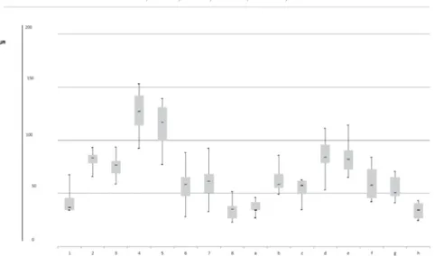
Figure 3-$FFXUDF\RI¿WRIHDFKPHDVXULQJSRLQWLQJURXS&(5(&6:Pm). Uppermost point and lowermost point indicate the highest and lowest values of results. The top of box and bottom of box indicate the 75% and 25% values of results. The midline in the box means the average of the results
Figure 4-$FFXUDF\RI¿WRIHDFKPHDVXULQJSRLQWLQJURXS&(5(&6:Pm). Uppermost point and lowermost point indicate the highest and lowest values of results. The top of box and bottom of box indicate the 75% and 25% values of results. The midline in the box means the average of the results
Although we expected the larger spacer parameter setting would have caused a larger gap between crown and tooth, the use of 40 Njm as the spacer parameter setting in the version 3.8 of the software produced a larger gap when compared to the setting of the spacer at 80 Njm for the six measuring points, including 5 (occlusal surface), 6 (upper axial wall), a (margin), b (lower axial wall), c (upper axial wall), and h (margin). On the contrary, for the version 4.2 of the software, one measuring point (i.e., point 6 of upper axial wall) showed a smaller gap with a 40 Njm spacer setting when compared with the group selecting 80 Njm, while the group selecting 80 Njm in the version 4.2 of the software showed the least variations among the results.
D I SCUSSI ON
The process of dental restorations using CAD/ CAM technology involves data acquisition, data processing, and manufacturing. The aim of this study was to evaluate the effect of data processing on the adaptation of crown restorations. Variables such as different versions of software and space parameters were analyzed in the four groups of crown impressions, and the ¿t of the crown was measured using the replica technique. As the results showed, the crowns designed using the version 4.2 of the software produced a better ¿t than those designed using the version 3.8 of the software, particularly in the axial wall. The spacer parameter was more accurately represented in the version 4.2 of the software than in the version 3.8. In addition, the use of the version 4.2 of the software combined Figure 6-$FFXUDF\RI¿WRIHDFKPHDVXULQJSRLQWLQJURXS&(5(&6:Pm). Uppermost point and lowermost point indicate the highest and lowest values of results. The top of box and bottom of box indicate the 75% and 25% values of results. The midline in the box means the average of the results
with the spacer parameter set at 80 Njm showed the least variation. On the other hand, the outer margin was not affected by the variables.
Such parameters indicate the setting factors to determine particular features of a restoration in CAD/CAM system. The cement space, the contact strength, the occlusion strength, and the minimum thickness of a restoration can be easily changed as providing different parameter in the CAD/CAM
system. Space parameter can be set from -100 to 100 Njm in the version 3.8, and from 0 to 100 Njm in the version 4.2. Among the overlapped space parameter (from 0 to 100 Njm), 40 and 80 Njm were used in this study. Forty Njm is commonly used as space parameter because resin cements range from 20 to 35 Njm concerning the thickness of their ¿lm; the 80 Njm is the double value of 40 Njm to evaluate the effect of space parameter.
To fabricate well-¿tting dental crowns using CAD/CAM systems in the clinic, the optimal combination involving the intraoral scanner, the software version, and the milling machine is important. Although many studies have compared the ¿t of crown restorations fabricated with different intraoral scanners16,20 and milling machines19, there
have been few studies evaluating the effect of different versions of the software. The results of Figure 8- 0HDQ LQWHUQDO ¿W Pm) of each measuring points on mesiodistally sectioned surface. *indicates statistically VLJQL¿FDQWGLIIHUHQFHV
Figure 9- The results of each average values of measuring points categorized as margin (1, 8, a, h), lower axial wall (2, 7, EJXSSHUD[LDOZDOOFIDQGRFFOXVDOVXIDFHGHLQGLFDWHVVWDWLVWLFDOO\VLJQL¿FDQWGLIIHUHQFHV
Independent variable 6LJQL¿FDQFH
Software Version S
Space Parameter S
this study showed the ¿t of a restoration could be affected by the software version and the spacer parameter setting, even when the same scanner and milling machine were used. Compared to the version 3.8 of the CAD/CAM software, the version 4.2 of this software can be recommended for the fabrication of well-¿tting crown restorations, and for the appropriate regulation of the spacer parameter. Even though the 80-Njm spacer setting produced a larger gap, this setting could be recommended for the version 4.2 of the CAD/CAM software because it showed a good repeatability.
Adequate marginal gaps and internal ¿ts are decisive factors for the clinical longevity of crown restorations10. A large marginal gap can cause
discoloration, disintegration of cement, plaque retention, and gingival inflammation1,3. The
recommended marginal gap for the prevention of the above mentioned complications7,8 is below 100
Njm. The results obtained in this study showed a clinically acceptable marginal ¿t could be achieved regardless of the software version and of the spacer parameter settings, with an average gap of 35 Njm. A larger internal gap could produce restorative fractures and postoperative sensitivity. The results of this study demonstrated the version 3.8 of the software and the spacer parameter set at 40 Njm produced a relatively larger internal gap when compared with the version 4.2 of the software and with the spacer parameter set at 80 Njm. The use of a suf¿cient amount of cement with harder mechanical properties is recommended in these cases to avoid the complications caused by large internal gaps.
Although zirconia is one of the most popular materials used in the fabrication of crowns by utilizing the CAD/CAM system, the additional process of sintering may introduce variability among crowns. For the accurate evaluation of the effect of the version of the software and of the spacer parameter settings, LavaTM Ultimate Restorative,
a resin of nano ceramic material that does not require the sintering process was selected as the restoration material in this study11. Compared with
previous studies14,19, the smaller marginal and
internal gaps reported in this study could be due to the use of a different restoration material. The marginal adaptation was evaluated using the replica technique. Although measurements using a digital 3D scanner are precise, convenient, and easily visualized, the replica technique is the appropriate measurement tool for the accurate assessment of multiple points in the internal surface of restorations fabricated using the CAD/CAM system22.
T h e g e n e ra l l y r e c o g n i ze d i m p r ove m e n t introduced by the version 4.2 of the software compared with the version 3.8 is an increased convenience for the use of the CEREC CAD/CAM
system. The version 4.2.5 is already available these days, being a supplementary version of the 4.2 and it does not seem to have big functional differences with the version 4.2. The results of this study showed that a smaller internal gap could be obtained using the version 4.2 of the software, particularly at the axial wall, despite the fact the marginal gap was almost the same. The improvement of the adaptation obtained with the version 4.2 of the software could be in part due to differences in the pre-set space, basically providing space regardless of the parameter setting at the internal part between software versions. It has been shown that a greater internal space resulted in less marginal gap leading to less internal premature contact4; a greater internal space might
be necessary for achieving an adequate marginal gap in crown restorations, taking into account the accuracy and reproducibility of intraoral scanners and milling machines that are currently used with the version 3.8 of the software. Another possible explanation could be the improvement in resolution of the version 4.2 of the software during the processing of the acquired data through the intraoral scanner.
The application of the CAD/CAM technology in dentistry have been producing improvement not only in dental clinics but also in dental laboratories6.
Many studies are using the AD/CAM technology to compare it with conventional methods or to manage it as a tool to measure specimens. Our results suggest that, to achieve accurate comparisons across studies, all reports should specify the software version and the space parameter settings used (additional studies of reference on the effect of various software and parameters will be necessary).
CON CLUSI ON S
The ¿t of a crown restoration can be affected by the speci¿c CAD/CAM software version and by the parameter settings selected, even if the same scanner and milling machine were used. In comparison with the version 3.8 of the CAD/ CAM software, the version 4.2 of this software can be recommended for the fabrication of
well-¿tting crown restorations, and for the appropriate regulation of the spacer parameter. Even though the 80-Njm spacer setting produced a larger gap, this setting can be recommended for the version 4.2 of the CAD/CAM software because it has shown a good repeatability.
ACKN OW LED GEM EN TS
REFEREN CES
1- Addi S, Hedayati-Khams A, Poya A, Sjögren G. Interface gap size of manually and CAD/CAM-manufactured ceramic inlays/ onlays in vit ro. J Dent. 2002;30(1):53-8.
2- Albert FE, El-Mowafy OM. Marginal adaptation and microleakage of Procera AllCeram crowns with four cements. Int J Prosthodont. 2004;17(5):529-35.
3- Baig MR, Tan KB, Nicholls JI. Evaluation of the marginal ¿t of a zirconia ceramic computer-aided machined (CAM) crown system. J Prosthet Dent. 2010;104(4):216-27.
4- Bindl A, Mörmann WH. Fit of all-ceramic posterior ¿xed partial denture frameworks in vit ro. Int J Periodontics Restorative Dent. 2007;27(6):567-75.
5- Ender A, Mehl A. Accuracy of complete-arch dental impressions: a new method of measuring trueness and precision. J Prosthet Dent. 2013;109(2):121-8.
6- Fasbinder DJ. Clinical performance of chairside CAD/CAM restorations. J Am Dent Assoc. 2006;137(Suppl):22S-31S. 7- Gassino G, Barone Monfrin S, Scanu M, Spina G, Preti G. Marginal adaptation of ¿xed prosthodontics: a new in v it r o
360-degree external examination procedure. Int J Prosthodont. 2004;17(2):218-23.
8- Groten M, Girthofer S, Pröbster L. Marginal ¿t consistency of copy-milled all-ceramic crowns during fabrication by light and scanning electron microscopic analysis in vit ro. J Oral Rehabil. 1997;24(12):871-81.
9- Henkel GL. A comparison of ¿xed prostheses generated from conventional vs digitally scanned dental impressions. Compend Contin Educ Dent. 2007;28(8):422-4, 426-8, 430-1.
10- Keshvad A, Hooshmand T, Asefzadeh F, Khalilinejad F, Alihemmati M, Van Noort R. Marginal gap, internal ¿t, and fracture load of leucite-reinforced ceramic inlays fabricated by CEREC inLab and hot-pressed techniques. J Prosthodont. 2011;20(7):535-40. 11- Koller M, Arnetzl GV, Holly L, Arnetzl G. Lava ultimate resin nano ceramic for CAD/CAM: customization case study. Int J Comput Dent. 2012;15(2):159-64.
12- Laurent M, Scheer P, Dejou J, Laborde G. Clinical evaluation of the marginal ¿t of cast crowns - validation of the silicone replica method. J Oral Rehabil. 2008;35(2):116-22.
13- Li RW, Chow TW, Matinlinna JP. Ceramic dental biomaterials and CAD/CAM technology: state of the art. J Prosthodont Res. 2014;58(4):208-16.
14- Martins LM, Lorenzoni FC, Melo AO, Silva LM, Oliveira JL, Oliveira PC, et al. Internal ¿t of two all-ceramic systems and metal-ceramic crowns. J Appl Oral Sci. 2012;20(2):235-40.
15- Molin M, Karlsson S. The ¿t of gold inlays and three ceramic inlay systems. A clinical and in vit ro study. Acta Odontol Scand. 1993;51(4):201-6.
16- Nedelcu RG, Persson AS. Scanning accuracy and precision in 4 intraoral scanners: an in vit ro comparison based on 3-dimensional analysis. J Prosthet Dent. 2014;112(6):1461-71.
17- Ng J, Ruse D, Wyatt C. A comparison of the marginal ¿t of crowns fabricated with digital and conventional methods. J Prosthet Dent. 2014;112(3):555-60.
18- Otto T, De Nisco S. Computer-manufactured, direct ceramic restorations: a prospective, clinical 10-year study of Cerec CAD-CAM inlays and onlays. Schweiz Monatsschr Zahnmed. 2003;113(2):156-69.
19- Patzelt SB, Bishti S, Stampf S, Att W. Accuracy of computer-aided design/computer-computer-aided manufacturing-generated dental casts based on intraoral scanner data. J Am Dent Assoc. 2014;145(11):1133-40.
20- Patzelt SB, Emmanouilidi A, Stampf S, Strub JR, Att W. Accuracy of full-arch scans using intraoral scanners. Clin Oral Investig. 2014;18(6):1687-94.
21- Quintas AF, Oliveira F, Bottino MA. Vertical marginal discrepancy of ceramic copings with different ceramic materials,
¿nish lines, and luting agents: an in vit ro evaluation. J Prosthet Dent. 2004;92(3):250-7.
22- Rahme HY, Tehini GE, Adib SM, Ardo AS, Rifai KT. I n vit ro
evaluation of the "replica technique" in the measurement of the