A Comparison of the Communication Impact in CAN and
TTP/C networks when supporting Steer-by-Wire Systems
Fernando Ataide, Max Mauro Santos
Centro Universitário do Leste de Minas Gerais, Brazil
fhataide@inf.ufrgs.br; maxmauro@unilestemg.br
Francisco Vasques
University of Porto, Portugal
vasques@fe.up.pt
Abstract
Distributed real time system is a technology that is become widely used in diverse areas of application, including systems in vehicles, aircraft, locomotives, among others. Great part of these applications is considered critic. Hereupon, such systems must be predictable in relation to its logical result and its temporal behavior, same in operating under failure having to provide tolerances. Distributed real time system requires the use of deterministic and reliable communications mechanisms. A high trend in the automotive area is the replacing of great part of the mechanical and/or hydraulic systems for electronic systems, so called control-by-wire. To reach the objectives of the control-by-wire systems, it is necessary the use of distributed real time systems with fault tolerant properties.
This work presents a study about the communication requirements in x-by-wire systems. A theoretic content and a detailed study of temporal property of the CAN and TTP/C network communication are presented in the environment of simulation of the x-by-wire system.
Keywords: x-by-wire, CAN, TTP/C, distributed real time
systems, fault tolerance.
1. Introduction
The control tasks in vehicle, aircraft, among others are carry through for mechanical and/or hydraulic systems are being replaced for electronic intelligent systems, benefiting the costs, maintenance, volume and weight, among others factors. These electronic systems are called control-by-wire, e.g. steering systems (steer-by-wire), braking systems (break-by-wire) e flight control systems (fly-by-wire).
The objectives of the x-by-wire project was to achieve a framework for the introduction of such safety related fault tolerant electronic systems in vehicles (X-BY-WIRE TEAM, 1998).
Control-by-wire applications are classified as critical safety systems. Therefore, such systems must provide
fault tolerant. Herewith, the communication system must supply this requirement.
This paper is a resume of the course conclusion project, where was implemented a simulation of steer-by-wire in the CAN and TTP/C protocol.
2. Steer-by-Wire System
Currently steering systems without mechanical connections between steering wheel and wheels (such as steer-by-wire), still are not allowed in commercial cars. However, there is a strong trend pushing for advanced research in this direction.
This section presents a steer-by-wire case study. In this (JOHANNESSEN, P., 2001) it present a steer-by-wire system with six nodes interconnected for a TTP/C network. The implemented steering modes are normal two wheel steering, four wheel steering and parallel steering (Figure 1).
2-wheel steering 4-wheel steering parallel steering
Figure 1 Steering modes
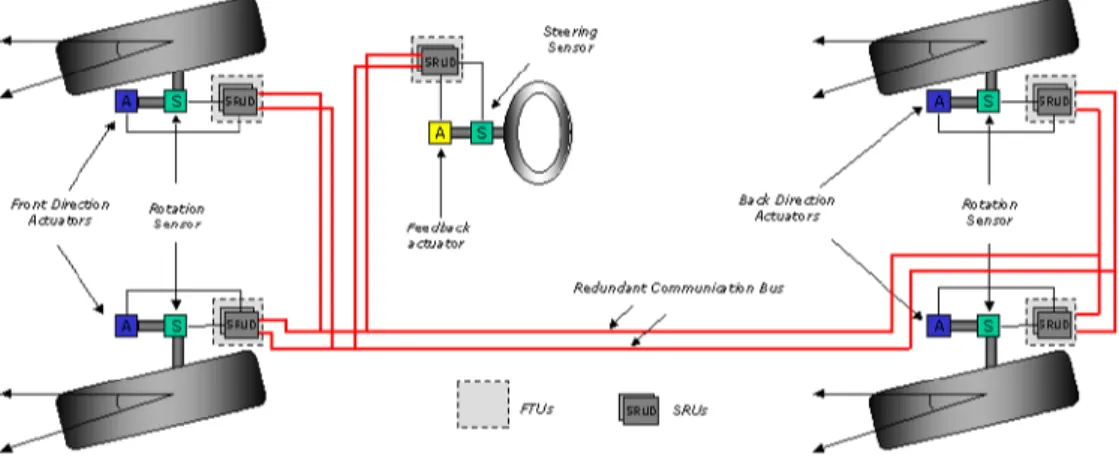
Each wheel has an individual controller that controls its angle of rotation, in accordance with the turn of the steering wheel. The angle of the wheels depends directly on the angle applied (for the driver) and for the selected steering mode. The Figure 2 presents such steer-by-wire system.
In this case uses a global update frequency of 100 Hz for continuous values and 10 Hz for mode control, where sensor data is broadcasted on the communication bus.
The calculations presented in Table 1 result in a effective bandwidth, not taking in consideration overheads for the communication protocol. Considering overhead in protocol TTP/C, we would have a consumption of bandwidth of 93.600 bits/s for this model, as presented in (JOHANSSON. R AND JOHANNESSEN, P, 2003).
Figure 2 Steer-by-wire systems
Table 1 Steer-by-Wire communication bandwidth Central Nodes
Steering wheel angle 14 bits x 100 Hz
Steering mode 2 bits x 10 Hz
Redundant sensor in C1 and C2 x 2
2840
Wheel Node
Wheel speed and steer angle (steer angle sensor
duplicated) 3 x 12 bits x 100 Hz
Four command words and one status word from all four nodes
((4 x 14 bits) + 16 bits) x 4 x 100 Hz
32400
Resulting bandwidth (bits/s) 35.240
3. Communication Requirements of
automotive systems
As presented in previous sections, the x-by-wire technology is characterized for requiring a distributed computational architecture (TÖRNGREN e WIKANDER, 1996) where the fault tolerance requirements and temporal behavior, among others, are important factors in the automotive systems project.
The SAE (Society of Automotive Engineers) describes a network communications classification in relation to the applications requirements.
- Class A Network of communication with low
bandwidth in not critical applications, such as the electronic body applications (control lamps and diagnostic). The LIN is Class A network.
- Class B Network used in the important applications,
but not essential for the operation (locomotion) of the automobile, such as information display, fuel level. The Class A and B are applied in the electronic body. The CAN is Class B network.
- Class C Network used in the safety critical
applications of distributed real time involved in the electronic systems (KOPETZ, H., 1995), which are directly related with the locomotion, e.g. steering control and braking control. The data volume is large demanding low latency with high bit rate. TTP/C and FlexRay are examples of the Class C. A network communication for application based in Class C must obligatorily possess the following requirements: High performance and predictability; Dependability; Scalability; Atomic broadcast; Composability; Communication error detection; Nodes error detection; Bus error detections.
In the safety critical systems exist time restriction, in other word, must carry through the task correctly and inside of a time limit determined in project (deadline of task). Understanding that the delay produced for a fault will not have to affect deadline task. Thus, also the regularity of the information transference must be assured together to jitter minimum. In an hard real time environment must be guaranteed that the worse case execution time (WCET) of the services is minor that client response time.
4. Event Triggered vs. Time Triggered
Communication
With relation to the trigger communication mechanisms, two distinct approach (KOPETZ. H, 1991) are used in real time communication systems, event-triggered and time-event-triggered.
4.1. Event-Triggered
In the event-trigger system all the activities are triggered due to occurrence of a significant event or a state change. In event-trigger communication protocol, the transmitting node only has knowledge of the time instant that the message will be transmitted.
The error detention is based on timeout of acknowledgment message, characterizing it as an implicit control. Variant latency is a temporal behavior uncertainty of asynchronous communication protocols, which can generate adverse occurrences how much to the predictability of the system. In temporal point of view, event-trigger systems are not composable.
4.2. Time-Triggered
The information dissemination of the state of one determined entity for all the nodes in a distributed real time system is basic in time-trigger system.
In time-trigger communication protocols it is responsibility of the receiver to verify if all the messages are available in the correct times, characterizing a explicit control. Is of this form that is carried through the error detention in time-trigger communication protocols. A way to provide fault tolerance is to carry through messages redundancies.
The time-triggered approach, due its regular mechanism in the time, possess greater predictability compared to the event-triggered approach. Compared to the implementation, a time-triggered project requires details with relation to the temporal properties of them control algorithms and messages transmission of all the nodes.
The worse case execution time (WCET) of the tasks, messages transmission time and execution schedule must be calculated in project time, resulting a predictable temporal behavior of the system.
In a event-trigger system, these details are not necessary, but demand greater tests time. Time-trigger systems are composable in that it says to the temporal property.
The hardware architecture in this approach, we have we the following differences:
In a event-trigger system the application is responsible for triggers events in the controller, which will transmit the messages for the network. In a time-trigger system the application does not interfere in the executed processes in the controller, in this in case include a CNI (Communication Network Interface) that
is a dual port RAM memory, where are shared the transmitted and received messages. The controller has a messages list and its transmission and reception times. Thus the application make available messages data in the CNI and the controller, in the certain instant, collects this information and sends the message for the network. Functioning in the same way in the inverse mode. The architecture time-triggered is a composable architecture.
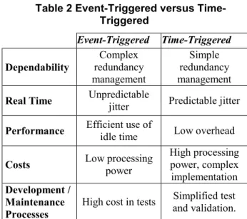
Table 2 presents an evaluation between the two approaches.
Table 2 Event-Triggered versus Time-Triggered Event-Triggered Time-Triggered Dependability Complex redundancy management Simple redundancy management
Real Time Unpredictable jitter Predictable jitter
Performance Efficient use of idle time Low overhead
Costs Low processing power
High processing power, complex implementation Development / Maintenance Processes
High cost in tests and validation. Simplified test
5. Real Time Network Communication
Characteristics and services details gifts in the two protocols are presented in the complete version of this report (ATAIDE and SANTOS, 2004). Follows below the important characteristics with relation to the temporal behavior of CAN and TTP/C protocol.
5.1. CAN Protocol
The CAN protocol (LAWRENZ, 1997), due its arbitration process, it has to high jitter for messages of low priorities and to low jitter for messages of higher priorities.
In an average load situation, the average of access to bus is low for all the messages. In peak cases load (maximum load) some messages with priority lower can have indefinite jitter. The CAN is a event-triggered protocol with CSMA/CA bus access principles.
This form the CAN protocol does not fulfill to all the Class C requirements of automotive applications. Although some authors consider it pertaining of Class C.
5.2. TTP/C Protocol
The TTP/C is a time-triggered protocol and possess bus access principles based in TDMA. These two main characteristics become the protocol TTP/C deterministic compared to the jitter variability. This if must to the
previous knowledge, by the nodes, of all the reception time and messages transmission time in the network.
Its hardware architecture projected for fault tolerance is an important characteristic in this protocol that becomes it widely employed in safety critical systems, as in automobile applications that possess Class C requirements.
6. Experiment
With objective to simulate the temporal behavior of CAN and TTP/C network in the medium access control protocol level in a automotive system, a steer-by-wire system simulation was implemented (presented in the section 2). The simulation was implemented on the Matlab/Simulink with TrueTime (HENRIKSSON D., 2002).
As the objective was to verify the temporal behavior in the protocol MAC level, the fault tolerance part was not considered in both the networks.
The steer-by-wire network communication is composite for five nodes. A node located in the vehicle steering, responsible for transmitting the movement information of the steering wheel (turn angle, left or right), besides receiving the messages from feedback comings from the controllers from each wheel (control messages and status). This feedback is used to imitate the real sensation of driven. The others nodes are located in each wheel, are responsible for receiving the information from the direction node and acting in the individual axis of each wheel conform direction mode selected (to see section 2), as also to send the
performance signal to the direction node (feedback). Figure 3 presents the block representation of this steer-by-wire model.
Figure 3 Steer-by-wire model in Matlab/Simulink
A trajectory previously was defined for introduction in the steer-by-wire experiment. Through this trajectory, a representative signal (reference signal in the Figure 4) will be collected by the direction node (green block in the Figure 3), in the steering wheel, and send for the wheels (orange block in the Figure 3), which will make the control (blue blocks in the Figure 3) of the steering displacement angle through this trajectory signal.
Figure 4 illustrates the trajectory signal (reference signal) and the trajectory.
Figure 4 Trajectory signal 6.1. Results under CAN Network
Considering the steer-by-wire system under CAN network with 500kbps of bit rate, the Figure 5 presents
the temporal behavior of the messages flow in the system.
The steering node (node 1) transmits a message with the steering mode information selected, with period of 100ms (Figure 5 (a)), followed of the message contends
the angle steering, with period of 10ms (Figure 5 (b)). The nodes of the four wheels, when receiving the message with the angle, effect the control, acting and transmission of a message for the steering node contend status information of wheel behavior (Figure 5 (c)). The left front wheel node (node 2) is responsible for transmitting a message for the steering node contends the speed and angle of the steering current (Figure 5 (d)). The event-triggered behavior of protocol CAN is noticed clearly, through the message receiving contend the angle (Figure 5 (b)) that it triggered the performance and transmission of the control message in the each wheel node (Figure 5 (c)). The message of state for containing 72bits of information to be transmitted, was partitioned in two frames, that are transmitted sequentially, of this form increasing the use of bandwidth in CAN network.
Figure 5 Message flow in steer-by-wire model in the CAN network
6.2. Results under TTP/C Network
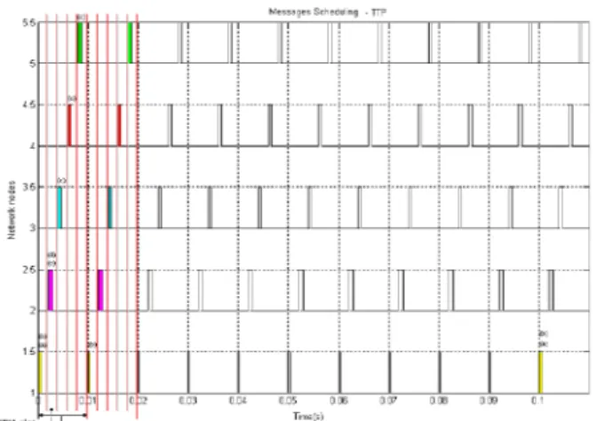
Considering the same messages flow in the TTP/C we have the behavior of the net illustrated in Figure 6. The steering node (node 1) transmitting the message contend the direction mode is identified in the point (a) of Figure 6, followed of the message contend the steering angle that is identified in point (b). The four wheels nodes transmitting the message with information of state, after effected the control and performance in the steering, is identified in the point (c). The left front steering node (node 1) transmitting the message for the wheel node, contend the speed and direction angle, is identified by the point (d). The time-triggered behavior of TTP/C protocol can be verified in details in Figure 6.
Figure 6 Message flow in steer-by-wire model in the TTP/C network
6.3. Wheel Actuation Behaviour in the CAN and TTP/C Network
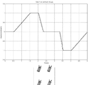
Is also noticed, a good accompaniment of the reference signal in the TTP/C and CAN network under 500kbps. Figure 7 presents the equivalent actuation behavior for the steering mode (4 wheels). Figure 8 presents the actuation behavior of one the front and one of the rear wheels, respectively, in parallel mode.
Figure 7 Wheel actuation in steering mode (4 wheels)
Figure 8 Wheels actuation in parallel mode
7. Conclusions and Perspectives
The CAN and the TTP/C are two different protocols compared to the communication type.
In the CAN network possess communication based on events (event-triggered) and the TTP/C based on the time progression (time-triggered). Both protocols possess different behaviors compared to the jitter variability. In the CAN, jitter of a message with high priority it is limited by the longest transmission interval, which is considered excellent. Messages with low priority have its jitter variable due to not the knowledge of the instant and transmission regularity of the messages with higher priority. In an average load situation, the average of access to the bus is low for all the messages. In peak cases load (maximum load) some messages with lower priority can have indefinite jitter.
In the TTP/C, which had its protocol TDMA, each node of the network has its time instant for transmission without collisions, do not possess jitter variable. Thus the TTP/C guarantees a high efficiency compared to jitter of that in protocol CAN. One another advantage of the TTP/C is its hardware architecture projected for fault tolerance, an important characteristic of this protocol that becomes it widely employed in safety critical systems.
8. References
X-By-Wire Team. X-By-Wire Safety Related Fault Tolerant Systems in Vehicles : Tech. Report, Project No. BE 95/1329, 1998
ISO 11898. Road Vehicle - Interchange of Digital Information - Controller Area Network (CAN) for High-Speed Communication : ISO, 1993.
Johannessen, P. Project SIRIUS 2001 : A University Drive-by-Wire Project, Tech. Report 01-14, Dept. of
Computer Eng., Chalmers University of Technology, Goteborg, Sweden, 2001.
Johansson. R, Johannessen, P. On Communication Requirements for Control-by-Wire Applications : Proceedings of the 21st International System Safety Conference, 2003
Ataide, F., Santos, M. Análise do Impacto da Comunicação em Redes CAN e TTP/C sob Sistemas Automotivos Steer-by-Wire : Course Conclusion Project, Laboratory of Real Time Systems, UnilesteMG, 2004.
TTTech, TTTech’s TTPBy-Wire Box – The Control Box for Brushless DC Motors : Technical Report, Vienna, Austria, 2003.
Tovar E., Vasques F. Real-Time Fieldbus Communications Using PROFIBUS Networks. : In IEEE Transactions on Industrial Electronics : Vol. 46, nº6, pp. 1241-1251,1999.
Kopetz. H., Event-Triggered versus Time-Triggered Real Time Systems : Research Report Nr. 8/91 : Institut fur Technische Informatik der Technischen Universitat Wien, 1991
Kopetz. H., Automotive Electronics Present State and Future Prospects : 25th Int. Symposium on Fault-Tolerant Computing, Los Angeles, USA June 1995.
Törngren, M. and J. Wikander. A decentralization methodology for realtime control applications : Control Engineering Practice, 4:2, pp. 219–228, 1996.
Gäfvert, Magnus. Topics in Modeling, Control, and Implementation in Automotive Systems : ISSN 0280– 5316 : Lund, Suécia, 2003.
Lawrenz, W. CAN System Engineering: From Theory to Pratical Applications : New York : Springer Verlag, 1997.
Rockwell Automation. DeviceNet Product Overview : Publication DN-2.5, Rockwell, 1997.
Tindell, K., Burns, A. e Wellings, A. Calculating Controller Area Network (CAN) Message Response Time : In Control Engineering Practice, Vol. 3, No. 8, pp. 1163-1169, 1995.
Henriksson, D., Cervin, A., Årzén, K. TrueTime: Simulation of Control Loops Under Shared Computer Resources : In 15th IFAC World Congress on Automatic Control, Barcelona, Spain, July 2002.