D
Distributed and
Remote Fiber
Sensing Assisted
by Raman Effect
Hugo Fidalgo Martins
Física
Departamento de Física e Astronomia 2014
Supervisor
Orlando José dos Reis Frazão, Invited Assistant Professor of Departamento de Física e Astronomia da Faculdade de Ciências da Universidade do Porto and Senior Researcher at INESC Porto
Supervisor
Miguel González-Herráez, Associate Professor, Departamento de Electrónica de la Universidad de Alcalá
DEPARTAMENTO DE FÍSICA E
ASTRONOMIA DA FACULDADE
DE CIÊNCIAS DA
UNIVERSIDADE DO PORTO
DEPARTAMENTO DE
ELECTRÓNICA DE LA
UNIVERSIDAD DE ALCALÁ
DOCTORAL THESIS
DISTRIBUTED AND REMOTE FIBER
SENSING ASSISTED BY RAMAN EFFECT
This thesis was conducted under the supervision of
Prof. Dr. Orlando José dos Reis Frazão
Invited Assistant Professor of Departamento de Física e Astronomia da Faculdade de Ciências da Universidade do Porto and Senior Researcher at INESC TEC
and
Prof. Dr. Miguel González-Herráez
Associate Professor of Departamento de Electrónica de la Universidad de Alcalá
Hugo Fidalgo Martins
Bolsa de investigação da Fundação para a Ciência e a Tecnologia com a referência SFRH/BD/76991/2011, financiada pelo POPH – QREN – Tipologia 4.1 – Formação Avançada, comparticipada pelo Fundo Social Europeu e por fundos nacionais do MCTES.
Acknowledgements
I would like to thank to everyone who contributed with work, time and patience to the realization of this thesis.
Firstly to my Portuguese supervisors Dr. Orlando Frazão and Professor Manuel Joaquim Marques, for accepting my PhD application and continuing to unconditionally support my work, after having already supervised my Master thesis. To Dr. Orlando Frazão, for his support and the help provided in all the stages of the experimental work developed in Portugal, from the numerous ideas to the scientific discussions, without forgetting his constant presence around the laboratory. Also for facilitating an initial contact with Professor Miguel González-Herráez, essential to arrange my research activity at the University of Alcalá. Special thanks to Professor Manuel Joaquim Marques, not only for the scientific discussions that were helpful to clarify the theoretical concepts necessary for a better understanding of optics in fibres and the help in writing the thesis, but also for assisting me with the process for the agreement of the jointly awarded PhD between the University of Porto and University of Alcalá and other bureaucratic procedures, which sometimes proved to be far more time and patience consuming than anticipated.
To my Spanish supervisor Professor Miguel González-Herráez for receiving me and providing the necessary arrangements for a most successful stay in the University of Alcalá. His expertise in distributed sensing provided an insightful understanding of numerous concepts and valuable help in the work developed in this area.
Especial thanks to Sonia Martin-Lopéz for introducing me to the laboratories and assisting me in the experimental work, especially at the beginning of my stay in Alcalá. To Pedro Corredera and Juan Diego for their good mood and the material borrowed from the “Consejo Superior de Investigaciones Cientificas” (CSIC).
To Professor Luc Thévenaz for receiving me in École Polytechnique Fédérale de Lausanne (EPFL) to test the possibility to perform distributed birefringence measurements using ϕOTDR and to Dr. Marcelo Soto and Xin Lu for working with me
during my stay in EPFL. This collaboration was also possible due to the support provided by COST Action TD1001 (OFSeSa).
To Dr. Cristiano Cordeiro from Instituto de Física Gleb Wataghin, UNICAMP, for providing a three core PCF which was used as an intensity curvature sensor.
To Dr. Kay Schuster and Dr. Jens Kobelke from IPHT Jena for providing a double-core fibre which was used as an in-line MZ interferometer.
To my co-workers and friends from INESC TEC and Alcalá, for their companionship and good mood necessary to create a positive work environment.
To INESC TEC, the Physics and Astronomy Department of Faculdade de Ciências da
Universidade do Porto and the Universidad of Alcalá for the opportunity and logistical
support which allowed the realization of my PhD degree.
I also would like to acknowledge the PhD scholarship from FCT Fundação para a Ciência e a Tecnologia (Portuguese Foundation for Science and Technology), SFRH / BD / 76991 / 2011.
To my family, for their care, trust and comprehension through the years.
And last but not least, to my dearest wife Inês, for her patience and care, and for her help in the editing corrections of several publications, including this very thesis.
Abstract
In this thesis, the work developed in the Physics PhD Degree project is presented. The work was focused on distributed and remote optical fibre sensing assisted by Raman effect.
Throughout the thesis, an effort has been made to present solid but also academic analysis of the proposed configurations, which often included both experimental and theoretical results as well as qualitative and quantitative explanations of the physical principles of the measurement techniques.
A special emphasis has been given to the use of phase-sensitive optical time domain reflectometry (ϕOTDR) for distributed vibration sensing, which was extensively described both experimentally and theoretically using different configurations, including the use of first and second-order Raman amplification to extend the sensing range.
The use of ϕOTDR for static measurements was also studied: a technique based on the correlation of ϕOTDR measurements at two orthogonal states of polarization was proposed to measure local variations of the phase birefringence along any kind of optical fibre.
A new configuration for an intensity vibration sensor based on a Raman fibre laser is proposed for remote point sensing. In this case, the linear cavity of the Raman fibre laser relied on the combination of a distributed Rayleigh mirror and FBGs (Fibre Bragg Gratings), which were used as the sensing element and intensity filter.
As a result of parallel projects which were not directly connected to the main theme of the thesis, it was possible to test microstructured fibres for different applications. An intensity curvature sensor based on a three core Photonic Crystal fibre and a high-sensitivity strain and temperature sensor based on a dissimilar-doping dual-core fibre were proposed.
Resumo
Nesta tese, é apresentado o trabalho desenvolvido durante o projeto de Doutoramento em Física. O trabalho focou-se em sensores em fibra ótica distribuídos e remotos assistidos pelo efeito Raman.
Ao longo da tese, foi feito um esforço para apresentar uma análise robusta, mas também académica, das configurações propostas, que, muitas vezes, incluiu resultados experimentais e teóricos, bem como explicações qualitativas e quantitativas dos princípios físicos das técnicas de medição.
Foi dada especial importância ao uso de reflectometria ótica no domínio do tempo sensível à fase (ϕOTDR) para medição distribuída de vibrações, que foi extensivamente descrito a nível experimental e teórico, usando diferentes configurações, incluindo o uso de amplificação de Raman de primeira e segunda ordens para aumentar o alcance de deteção.
O uso de ϕOTDR para medições estáticas foi também estudado: uma técnica baseada na correlação de medições de ϕOTDR em dois estados de polarização ortogonais foi proposta para medir variações locais da birrefringência de fase ao longo de qualquer tipo de fibras óticas.
Uma nova configuração para um sensor de vibrações interrogado em intensidade baseada num laser de Raman em fibra foi proposta para um sensor pontual remoto. Neste caso, a cavidade linear do laser Raman em fibra baseava-se na combinação de um espelho Rayleigh distribuído e redes de Bragg em fibra, que foram usadas como elemento sensor e filtro de intensidade.
Como resultado de projetos paralelos, não diretamente relacionados com o tema principal desta tese, foi possível testar fibras microestruturadas para diferentes aplicações. Um sensor de curvatura interrogado em intensidade baseado numa fibra de cristal fotónico com três núcleos e um sensor de elevada sensibilidade de deformação e temperatura, baseado numa fibra com dois núcleos de dopagem distinta foram propostos.
Resumen
En esta memoria se presenta el trabajo realizado en el proyecto de doctorado en física. El trabajo se centra en el estudio de sensores de fibra óptica distribuidos y remotos asistidos por efecto Raman.
A lo largo de la tesis se hizo un esfuerzo para presentar, no solo un análisis sólido, sino también riguroso, de las configuraciones propuestas, que incluyen con frecuencia resultados experimentales y teóricos, así como explicaciones cualitativas y cuantitativas de los principios físicos de las técnicas de medición.
Se prestó especial atención a la utilización de la reflectometría óptica en el dominio del tiempo sensible a la fase (ϕOTDR) para medición distribuida de vibraciones, que se describe ampliamente desde la punto de vista tanto experimental como teórico, usando diferentes configuraciones e incluyendo el uso de la amplificación de Raman de primer y segundo orden para extender el rango de detección.
Se ha estudiado también el uso de ϕOTDR para mediciones estáticas: se propuso una técnica basada en las medidas de correlación ϕOTDR en dos estados ortogonales de polarización con el objeto de medir las variaciones locales de la birrefringencia de fase a lo largo de cualquier tipo de fibra óptica.
Se propuso una nueva configuración de sensor de vibración interrogado en intensidad basado en un láser Raman en fibra para un sensor puntual remoto. En este caso, la cavidad lineal del láser Raman en fibra se basa en una combinación de un espejo Rayleigh distribuido y redes de Bragg en fibra, que se utilizaron como elemento sensor y filtro de intensidad.
Como resultado de proyectos paralelos, que no están directamente relacionados con el tema principal de esta tesis, fue posible probar fibras microestruturadas para diferentes aplicaciones. Se han propuesto un sensor de curvatura interrogado en intensidad basado en una fibra de cristal fotónico con tres núcleos y un sensor de elevada sensibilidad a la deformación y la temperatura, basado en una fibra con dos núcleos con dopaje distinto.
Contents
Acknowledgements ... vii Abstract ... ix Resumo ... x Resumen ... xi Contents ... xii List of Figures ... xvList of Acronyms ... xix
1 Introduction ... 1
1.1 Contextualization of the work ... 3
1.2 Motivation and Objectives ... 5
1.3 Organization of the Dissertation ... 6
1.4 Main Contributions ... 7
1.5 List of Publications ... 8
1.5.1 Articles published in International Scientific Journals (6) ... 8
1.5.2 Conference Proceedings (11) ... 8
2 Optical effects in fibres... 11
2.1 Introduction ... 13
2.2 Linear effects ... 13
2.2.1 Optical Losses: absorption and scattering ... 14
2.2.2 Chromatic Dispersion ... 16
2.2.3 Polarization-mode dispersion ... 18
2.3 Nonlinear Propagation ... 20
2.3.1 Parametric nonlinearities ... 20
2.3.2 Nonlinear refractive index ... 21
2.3.2.1 Modulation Instability (MI) ... 22
2.4 Scattering ... 25
2.4.1 Elastic scattering: Rayleigh scattering ... 26
2.4.1.1 Rayleigh Backscattering ... 27
2.4.2 Inelastic scattering: Raman Scattering ... 28
2.4.2.1 Spontaneous Raman scattering... 28
2.4.2.2 Stimulated Raman Scattering (SRS) ... 29
2.4.2.3 Raman Gain Spectrum ... 31
2.4.2.4 Intensity evolution and threshold for noise amplification ... 32
3 Phase-sensitive OTDR (ϕOTDR) for distributed vibration sensing ... 35
3.1 Introduction ... 37
3.2.1 ϕOTDR principle of operation... 39
3.2.2 ϕOTDR Historical Perspective ... 43
3.2.2.1 Events and vibration detection ... 44
3.2.3 Detection Schemes and Noise ... 45
3.2.3.1 Direct detection and noise in ϕOTDR operation ... 46
3.2.3.2 Coherent detection... 48
3.2.4 Post-processing ... 50
3.2.5 Range increase ... 51
3.2.5.1 ϕOTDR Peak power limitations due to nonlinearities ... 52
3.2.5.2 Raman Amplification ... 53
3.2.5.3 Brillouin Amplification ... 54
3.2.6 Bandwidth increase... 55
3.2.7 ϕOTDR for dynamic sensing: Performance overview ... 56
3.2.8 Comparison with other DFOS ... 57
3.2.8.1 Rayleigh based distributed sensing ... 57
3.2.8.2 Raman based distributed sensing ... 59
3.2.8.3 Brillouin based distributed sensing ... 60
3.3 ϕOTDR for distributed vibration sensing ... 62
3.3.1 Introduction ... 62 3.3.2 Theoretical Model... 62 3.3.2.1 Signal statistics ... 62 3.3.2.2 Signal-to-noise ratio (SNR) ... 64 3.3.3 Experimental Work... 65 3.3.3.1 Setup ... 65
3.3.3.2 ϕOTDR trace characterization... 67
3.3.3.3 Vibration Measurements ... 69
3.3.4 Conclusions ... 73
3.4 ϕOTDR Pulse Peak Power limitation: Modulation Instability (MI) ... 74
3.4.1 Introduction ... 74
3.4.2 Theoretical Model: Pulse propagation affected by MI ... 74
3.4.3 Experimental Work... 75
3.4.3.1 MI impact on the ϕOTDR trace ... 76
3.4.3.2 Pulse spectra at the fibre end (in transmission) ... 77
3.4.4 Conclusions ... 79
3.5 Extending the sensing range: ϕOTDR assisted by first-order Raman ... 80
3.5.1 Introduction ... 80
3.5.2 Theoretical Model: ϕOTDR pulse power evolution along the fibre... 80
3.5.3 Experimental Work... 82
3.5.3.1 Setup ... 82
3.5.3.2 Noise Considerations: ASE, RIN transfer and Balanced detection .. 84
3.5.3.3 ϕOTDR Traces ... 87
3.5.3.4 Evolution of the ϕOTDR trace for different Raman Pump powers .. 90
3.5.3.5 Vibration Measurements ... 90
3.5.4 Conclusions ... 94
3.6 Extending the sensing range: ϕOTDR assisted by second-order Raman... 95
3.6.1 Introduction ... 95
3.6.2 Experimental Setup ... 95
3.6.3 RIN noise: Balanced VS Direct detection ... 96
3.6.5 Vibration measurements ... 99
3.6.6 Spatial Resolution ... 100
3.6.7 Conclusions ... 101
3.7 ϕOTDR for distributed vibration sensing: Conclusions ... 102
4 ϕOTDR for distributed birefringence measurements ... 103
4.1 Introduction ... 105
4.2 State-of-the-Art ... 105
4.3 ϕOTDR for static measurements: Theoretical model ... 106
4.3.1 Birefringence measurements ... 108 4.4 Experimental Work ... 109 4.4.1 Setup ... 109 4.4.2 Birefringence of PMFs ... 110 4.4.3 Birefringence of SMFs ... 111 4.5 Conclusions ... 112
5 URFL for remote vibration sensing ... 115
5.1 Introduction ... 117 5.2 State-of-the-Art ... 117 5.3 Experimental Work ... 118 5.4 Discussion ... 123 5.5 Conclusions ... 124 6 Other Contributions ... 125
6.1 Intensity curvature sensor based on a photonic crystal fibre with three coupled cores 127 6.1.1 Introduction ... 127
6.1.2 Experimental Work... 128
6.1.3 Conclusions ... 132
6.2 High sensitivity dispersive Mach-Zehnder interferometer based on a dissimilar-doping dual-core fibre for sensing applications ... 134
6.2.1 Introduction ... 134
6.2.2 Theoretical Model... 135
6.2.3 Experimental Work... 138
6.2.4 Conclusions ... 142
7 Final Conclusions and Future Work ... 143
7.1 Final Conclusions ... 145
7.2 Future Work ... 146
List of Figures
Fig. 2.1 Typical loss spectrum for a silica fibre (Adapted from ref. [10]). ... 16
Fig. 2.2 Different types of PMF: a) Panda, b) Bow-tie, c) Elliptical-clad (Adapted from ref. [13]). ... 19
Fig. 2.3 Gain spectrum induced by MI using the parameters of a typical SMF. ... 24
Fig. 2.4 Energy variations for different types of scattering (Adapted from ref. [18]). ... 26
Fig. 2.5 Rayleigh scattering of light propagating in a dense inhomogeneous medium. . 27
Fig. 2.6 Counter-propagating wave generated by Rayleigh backscattering in fibres. .... 28
Fig. 2.7 Stimulated Raman a) Stokes and b) anti-Stokes scattering. ... 30
Fig. 2.8 Raman gain spectrum R g (Ω) for fused silica (Adapted from ref. [9])... 31
Fig. 3.1 Setup of an OTDR based system. FUT: fibre under test. ... 39
Fig. 3.2 Propagation of an OTDR pulse in the fibre and respective Rayleigh backscattered signal generated at a time: a) t=T; b) t=T+∆t/2.; c) the backscattered signals reflected at different times reaching the detector (z=0) at t=2T. ... 40
Fig. 3.3 Typical trace of: a) conventional OTDR; b) ϕOTDR. ... 42
Fig. 3.4 ϕOTDR trace before and after a disturbance occurs at a point in the fibre. ... 42
Fig. 3.5 ϕOTDR setup used for intrusion sensing in fields tests (adapted from ref. [33]). ... 44
Fig. 3.6 Practical setup of a ϕOTDR using coherent detection. ... 48
Fig. 3.7 Power distribution along the fibre for a ϕOTDR pulse with finite ER. ... 65
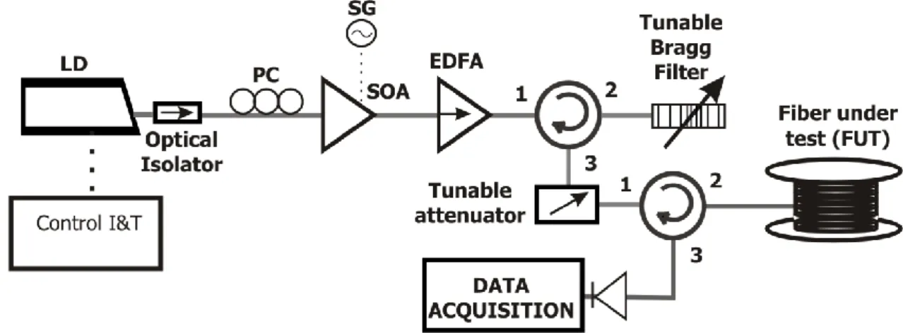
Fig. 3.8 Experimental setup of the ϕOTDR used for distributed vibration sensing. ... 66
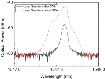
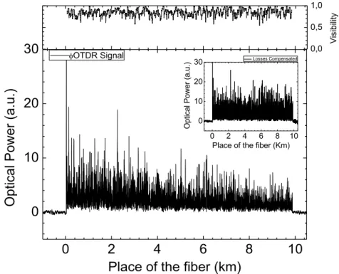
Fig. 3.9 Spectrum of a low coherence laser before and after passing through the SOA. 67 Fig. 3.10 ϕOTDR trace for a pulse peak power of ~400 mW (figure inset: losses have been numerically compensated to improve visualization). The top figure shows the visibility of the trace. ... 68
Fig. 3.11 Experimental (5∙106 traces obtained under the same conditions of the one presented in Fig. 3.10, over ≈10 min) and theoretical optical intensity distribution in the ϕOTDR trace (figure inset: cumulative probability function). ... 69
Fig. 3.12 ϕOTDR signal at the position corresponding to the metre length inside the tube (590 m) for an applied vibration of 20 Hz: a) Optical power variation along time and b) respective FFT. ... 70
Fig. 3.13 Normalized sensitivity of the measurement as a function of the normalized average optical power of the ϕOTDR trace at the measured point (left) and its histogram (right). ... 72 Fig. 3.14 FFT spectra of the optical power variation of the ϕOTDR time signal at a given position for an applied vibration frequency from 2 kHz to 39.5 kHz... 73 Fig. 3.15 Simulation of the ϕOTDR pulse spectrum evolution along an SMF for a ϕOTDR pulse peak power of 1.25 W. ... 75 Fig. 3.16 ϕOTDR trace and theoretical fraction of power contained in the central wavelength along the FUT for a ϕOTDR pulse peak power of ~1.25 W (main figure) and ~0.35 W (figure inset). The top figure shows the visibility of the ϕOTDR signal of the main figure. ... 76 Fig. 3.17 Normalized optical power of the peak and sidebands at the end of the FUT for different ϕOTDR pulse powers (inset figures: spectrum for ϕOTDR pulse powers of: a) 24.5 dBm, b) 27.8 dBm and c) 28.8 dBm). ... 78 Fig. 3.18 Experimental setup of ϕOTDR assisted by first-order Raman amplification. 83 Fig. 3.19 Spectra of the ϕOTDR pulses after passing the optical switch in the “on” and “off” states ... 84 Fig. 3.20 Optical spectrum returning from the FUT: a) before the micro-EDFA and b) after the micro-EDFA (including signals received in the “+” and “-” ports of the balanced detector (signal channel and adjacent channel))... 85 Fig. 3.21 Comparison of the RIN for a) Direct b) Balanced detection in a 75 km FUT. 86 Fig. 3.22 RIN noise returned from 125 km FUT for a Raman pump power of 0.6 W launched on each end of the fibre, without input ϕOTDR pulse, using balanced and direct detection. ... 87 Fig. 3.23 ϕOTDR trace for a FUT of a) 110 km and b) 125 km. The Raman pump power launched on each end of the fibre was 0.6 W and the ϕOTDR pulse power was chosen as the one ensuring the best performance in both cases. The theoretical modeling of the Raman pump power and ϕOTDR pulse power along the FUT is also presented. The top figure shows the visibility of the interference signal. ... 88 Fig. 3.24 Experimental and theoretical evolution of the trace profile for different Raman pump powers (total Raman input power), using a FUT of 110 km. The ϕOTDR pulse power chosen for each Raman pump power was the one ensuring the best performance. ... 90
Fig. 3.25 ϕOTDR signal at the fibre point with the minimum amplitude of the trace oscillations (km 98) of the 110 km FUT, using the same conditions of Fig. 3.23a, for an applied vibration of 40 Hz: a) Optical power variation along time and b) respective FFT. ... 92 Fig. 3.26 FFT spectra of the optical power variation of the ϕOTDR signal along time in the fibre point with minimum amplitude of the trace oscillations (after km 98) of the a) 110 km and b) 125 km FUT for applied frequencies between 10 Hz and a) 300 Hz and b) 250 Hz, using the same conditions of Fig. 3.23 for each FUT. ... 93 Fig. 3.27 Experimental setup of ϕOTDR assisted by second-order Raman amplification. ... 95 Fig. 3.28 Characterization of the noise in the electrical spectrum domain of the signal returning from the fibre when a Raman pump power of 28.5 dBm is launched on both ends of the FUT without input ϕOTDR pulse, using balanced and direct detections. ... 97 Fig. 3.29 ϕOTDR trace when the Raman pump power launched on each end of the FUT was 28.5 dBm. In this case, the ϕOTDR pulse power was chosen as the one ensuring the best performance. The top figure shows the visibility of the trace... 98 Fig. 3.30 FFT spectra of the optical power variation of the ϕOTDR signal along time at the point of the FUT with minimum signal, for applied frequencies between 20 Hz and 380 Hz, using the same conditions of Fig. 3.29. ... 100 Fig. 3.31 Normalized energy density of vibrations around 20 Hz along the FUT when a vibration of 20 Hz was applied to the PVC tube (at ~98.8 km). In the figure inset a gaussian fit of the points where the vibration was detected is shown, presenting 6 m at FWHM. ... 101 Fig. 4.1 Experimental setup of the ϕOTDR used for distributed birefringence measurements. ... 110 Fig. 4.2 Distributed profile of phase birefringence versus distance along a) 80 m Panda PMF and b) 100 m elliptical-core PMF. ... 110 Fig. 4.3 Distributed birefringence measurement in a SMF: a) Measured frequency and birefringence profile versus distance b) cross-correlation spectrum at 220 m distance. ... 112 Fig. 5.1 Experimental Setup of the Raman FBG laser intensity vibration sensor. ... 119 Fig. 5.2 Optical power output as a function of the Raman power input of the Raman FBG laser without the filter FBG (Figure inset: output spectra for the input Raman pump powers of 600 mW and 800 mW). ... 120
Fig. 5.3 Optical output spectra for maximum and minimum applied strain to the sensing head (FigureiInset: reflection spectra of the filter FBG and sensor FBG for maximum and minimum applied strain to the sensing head). ... 121 Fig. 5.4 Output optical power variation of the laser in the time domain for applied vibrations of different frequencies (arbitrary optical power reference level). ... 121 Fig. 5.5 Central frequency output power (converted electric signal) for applied vibrations of different frequencies (Figure inset: output power in the frequency domain for 100 Hz and 260 Hz). ... 122 Fig. 5.6 Amplitude of the vibration as a function of the maximum strain variation (induced by applying an electrical signal to the PZT). ... 123 Fig. 6.1 Experimental setup of the bending sensor based on a PCF with three coupled cores. ... 128 Fig. 6.2 Cross-section of the PCF with three cores with a magnification of 865x (inset figure with a magnification of 9000x). ... 129 Fig. 6.3 Spectral response for different applied curvatures (reflection setup). ... 130 Fig. 6.4 Average optical power vs curvature for rotation angles of 0º, 30º and 90º of the PCF along its axis (Solid lines are a linear fit of the experimental data; for the 30 degrees measurements two regimes are considered: low curvatures (0-1.5 m-1) and high curvatures (1.7-2.8 m-1)). ... 131 Fig. 6.5 Cross-section of the dual-core fibre, showing the germanium and phosphorous doped cores. ... 135 Fig. 6.6 Theoretical phase (the lines) of the interferometer as a function of the wavelength for a fibre at a) Room temperature with no strain, b) temperature applied, c) strain applied. The experimental peaks are also represented (dots). The values used in the simulation are presented in the text. ... 138 Fig. 6.7 Experimental setup used to characterize the dual-core fibre as a strain and temperature sensor. ... 139 Fig. 6.8 Shift of the normalized transmission spectrum of the dispersive interferometer with increasing applied a) strain and b) temperature. ... 140 Fig. 6.9 Peaks wavelength shift of the dispersive interferometer spectrum as a function of the applied a) strain and b) temperature. ... 141
List of Acronyms
ϕOTDR – Phase-sensitive optical time domain reflectometry
ASE – Amplified Spontaneous Emission BOTDA – Brillouin Optical Time Domain
Analysis
BOTDR – Brillouin optical time domain reflectometry
COTDR – Coherent OTDR CW – Continuous wave
DBG – Dynamic Brillouin gratings DC – Direct current
DCF – Dispersion Compensating fibre DFB – Distributed-Feedback
DFOS – Distributed fibre optic sensors DFWM – Degenerate Four-wave mixing DPP – Differential Pulse-Width pair DTS – Distributed temperature sensing EDFA – Erbium-Doped fibre Amplifier EOM – Electro-Optic Modulator ER – Extinction Ratio
ESA – Electrical Spectrum Analyzer FBG – fibre Bragg grating
FFT – Fast Fourier Transform FPU – Fermi-Pasta-Ulam FUT – fibre Under Test
FWHM – Full-Width at Half-Maximum FWM – Four-wave Mixing
GDD – Group delay dispersion GVD – Group Velocity Dispersion IR – Infrared
IYL – International Year of Light LD – Laser Diode
LO - Local oscillator MI – Modulation Instability MMF – Multimode fibres
MZ – Mach-Zehnder
MZI – Mach-Zehnder interferometer NLSE – Nonlinear Schrödinger Equation OFDR – Optical Frequency Domain
Reflectometry
OSA – Optical Spectrum Analyzer
OTDR – Optical time domain reflectometry PC – Polarization Controller
PCF – Photonic Crystal fibre PDL – Polarization dependent loss PMD – Polarization-mode dispersion PMF – Polarization-maintaining fibre POTDR – Polarization OTDR PSw – Polarization Switch PZT – Piezoelectric element RFL – Raman fibre Laser RIN – Relative Intensity Noise RMS – Root mean square
SBS – Stimulated Brillouin scattering SFG – Sum-Frequency Generation SG – Signal Generator SHG – Second-Harmonic Generation SMF – Single-mode fibres SMS – Single-Mode-Multimode-single-mode SNR – Signal-to-noise ratio
SRS – Stimulated Raman scattering SOA – Semiconductor Optical Amplifier SOP – State of polarization
SPM – Self-phase Modulation TOD – Third-order dispersion TOF – Tuneable Optical Filter URFL – Ultralong Raman fibre laser UV – Ultraviolet
WDMs – Wavelength division multiplexers XPM – Cross-phase modulation
1.1 Contextualization of the work
In the 21st century, light based technology plays a vital role in our daily lives, having revolutionized areas as important as medicine, internet communications, among several others. The importance of such systems is well established and recognized by prestigious international entities: in 2009 Charles Kao won the Nobel Prize in Physics for "groundbreaking achievements concerning the transmission of light in fibres for
optical communication"; in the end of 2013, the United Nations (UN) proclaimed 2015
as the International Year of Light and Light-based Technologies (IYL 2015).
In the context of optical fibres, a number of linear and nonlinear effects can be generated which can set limitations or be used in an advantageous manner, depending on the specific situation. Rayleigh scattering is the main effect responsible for fibre losses in the 1.55 μm region. Brillouin scattering can limit the transmitted power, especially with narrowband optical signals. Modulation instability (MI) and Raman scattering can generate and amplify noise at frequencies near that of the main signal. However, using the same effects, Rayleigh backscatter, Brillouin and Raman effects can also be used for distributed sensing and MI has been used to generate stable ultra-short pulses. Raman amplification has also been widely studied and reported in the scientific literature as a way to increase the sensing range and signal-to-noise ratio (SNR) of optical communications and sensing systems. Understanding these optical effects is therefore of fundamental importance, whether to limit their impact on existing optical systems or to develop new ones.
Among light based systems, the specific interest in fibre optic sensors has increased significantly over the last decade due to their intrinsic properties, such as immunity to electromagnetic noise, small size, geometric versatility, lightweight, relatively low cost, possibility of remote operation and multiplexing capability. In most systems, the fibre can be used as both the sensing element and the communication channel, which allows numerous convenient solutions using this type of technology. When the number of points to be monitored is very large, distributed sensors present clear advantages over conventional point sensors, due to their low cost per monitored point, and should therefore be preferred for monitoring large important infrastructures such as bridges, dams, railways, pipelines for gas and oil transport, high power electrical lines or national borders.
Several types of distributed fibre optic sensors have been demonstrated for monitoring different parameters at any point along a fibre. Optical time domain reflectometry (OTDR) is a Rayleigh backscatter based technique commonly used for distributed measurement of losses along the fibre (including the measurement of fibre attenuation, the location of broken points and optical connectors, discontinuities and others). Brillouin based sensing is traditionally used in strain and temperature sensing. The use of phase-sensitive OTDR (ϕOTDR) has been demonstrated for the distributed measurement of vibrations which can be used to monitor intrusions and, more recently, for highly sensitive distributed temperature measurements. Depending on the required spatial resolution, the distributed optical fibre sensors mentioned can typically present measuring ranges of up to a few tens of kilometers which, depending on the application, may not be enough.
In this context, the aim of this PhD program is to study the possibility of using the Raman effect to improve the performance, mainly the sensing range and SNR, of distributed and remote optical fibre sensors. Special care is taken with the detrimental phenomena associated with the technique, mainly the amplified spontaneous emission (ASE) noise introduced and the Relative Intensity Noise (RIN) transfer which can severely degrade the system performance.
1.2 Motivation and Objectives
The main motivations for the work reported in this PhD thesis were the study of the possibility of using the Raman effect to improve the performance of distributed and remote optical fibre sensors, mainly focused on vibration sensing.
Acquisition of further knowledge and better understanding of the different effects which occur in optical fibres, and of the fundamental physical mechanisms which lead to them, were also an ever present motivation for the work developed in this thesis.
The following objectives have been addressed in this PhD programme:
Perform a detailed study of ϕOTDR operation when used for distributed vibration sensing, including proper identification of the main linear and nonlinear effects which limit its performance, in order to avoid/minimize them in future systems.
Document the use of first- and second-order Raman amplification schemes to increase the performance of ϕOTDR distributed vibration sensing using the best configurations identified in the previous point. Characterize its performance as well as the limiting effects of the system, with especial attention to the RIN transfer and ASE noise introduced by the Raman pumps.
Investigate the possibility of using a Raman fibre laser (RFL) combined with fibre Bragg gratings (FBGs) for remote point sensing of vibrations with high SNR and optical intensity variation interrogation.
Work with microstructured fibres, evaluating the possibility to use them for optical sensing.
1.3 Organization of the Dissertation
This thesis is divided into seven chapters in which several concepts related to the work developed are described.
In chapter 1, besides the contextualization of the work and the description of motivation and objectives, a list of the main contributions and publications is presented.
In chapter 2, the physical explanation of the optical properties of the fibres used in this thesis is presented. Losses, dispersion and birefringence are discussed as linear effects. As for the nonlinear effects, parametric nonlinearities and nonlinear refractive index, which lead to the occurrence of MI in fibres, are discussed. Lastly, an overview of Rayleigh and Raman scattering processes is presented.
In chapter 3, an extensive investigation on the use of ϕOTDR for distributed vibration sensing, which includes experimental and theoretical descriptions using different configurations, is presented. The limitations due to MI are discussed and the performance of the different configurations, including the use of first and second-order Raman amplification, is analyzed.
In chapter 4, a method to measure local variations of the phase birefringence along any kind of optical fibre is proposed. The technique is based on the correlation of ϕOTDR measurements of two orthogonal states of polarization.
In chapter 5, a new configuration for a remote intensity vibration sensor based on a Raman fibre laser is proposed. The linear cavity of the Raman fibre laser relies on the combination of a distributed Rayleigh mirror and FBGs, which are used as the sensing element and intensity filter.
In chapter 6, two additional works, which resulted from parallel projects which were not directly connected to the main theme of the thesis, are presented. Firstly, a curvature sensor which uses a simple interrogation technique based on optical power variation using a Photonic Crystal fibre (PCF) is proposed. Then, a dual-core fibre, in which one of the cores is doped with Germanium and the other with Phosphorus, is used as an in-line Mach-Zehnder (MZ) dispersive interferometer, is characterized for strain and temperature measurement.
In chapter 7, the final conclusions of the thesis and some suggestions for future work are presented.
1.4 Main Contributions
The most important contributions which resulted from the work developed during this PhD programme are listed below:
- Theoretical and experimental in-depth descriptions of the impact of MI in the performance of a ϕOTDR are presented, to the best of our knowledge, for the first time. It has been demonstrated that MI generally leads to localized fading of the interference recorded in the trace and therefore to loss of sensitivity in these positions. This work can be useful for understanding the limitations imposed by MI in ϕOTDR operation in both dynamic and static measurements.
- An experimental and theoretical description of the use of first and second-order Raman amplification to improve the performance of ϕOTDR is presented. The detection of vibrations of up to 250 Hz and 380 Hz, respectively, over 125 km with a resolution of 10 m and no post-processing was achieved.
- A technique that uses the cross-correlation between ϕOTDR measurements of orthogonal states of polarization has been proposed and experimentally validated for distributed birefringence measurement. The method offers the possibility to discriminate local birefringence variations along many tens of km of optical fibres with metric spatial resolution. The high birefringence accuracy demonstrated (~10-7) enables proper distributed characterization of low birefringence single-mode fibres.
- A new device concept for a highly sensitive MZ interferometer, based on a dual-core fibre with dissimilar-doping, has been described theoretically and experimentally. Opposite sensitivities for wavelength peaks above and below the central wavelength of the interferometer were demonstrated when strain and temperature were applied. To our knowledge this is the first time that such behaviour was demonstrated using this type of in-line interferometer based on a dual-core fibre. A sensitivity of (0.102±0.002) nm/με, between 0-800 με, and (-4.0±0.2) nm/ºC between 47-62ºC, was demonstrated.
1.5 List of Publications
During the PhD thesis project the author published six papers in international scientific journals, all as first author.
The results obtained during the PhD thesis were also presented at seven international conferences and two national conferences. The references of the published articles and conference proceedings are listed below.
1.5.1 Articles published in International Scientific Journals (6)
[1] Martins, H.F., et al., Intensity Curvature Sensor based on Photonic Crystal fibre
with Three Coupled Cores, Optics Communications, 2012 285(24): pp.5128-5131.
[2] Martins, H.F., et al., Modulation instability-induced fading in phase-sensitive optical
time-domain reflectometry. Optics Letters, 2013. 38(6): p. 872-874.
[3] Martins, H.F., et al., Coherent Noise Reduction in High Visibility Phase-Sensitive
Optical Time Domain Reflectometer for Distributed Sensing of Ultrasonic Waves.
Journal of Lightwave Technology, 2013. 31(23): p. 3631-3637.
[4] Martins, H.F., M.B. Marques, and O. Frazão, Intensity vibration sensor based on
Raman fibre laser using a distributed mirror combined with Bragg grating structures.
Applied Physics B, 2014. 114(4): p. 455-459.
[5] Martins, H.F., et al., Phase-sensitive optical time domain reflectometer assisted by
first-order Raman amplification for distributed vibration sensing over >100km. Journal
of Lightwave Technology, 2014. 32(8): p. 1510-1518.
[6] Martins, H.F., et al, High-sensitivity dispersive Mach-Zehnder interferometer based
on a dissimilar-doping dual-core fibre for sensing applications, Optics Letters, 2014
39(9): pp.2763-2766.
1.5.2 Conference Proceedings (11)
1. -H. F. Martins, M. J. Marques, P. Jorge, C. M. B. Cordeiro, O. Frazão, "Intensity Curvature Sensor based on Photonic Crystal fibre with Three Coupled" Cores, SPIE Photonics Europe 201 - SPIE Photonics Europe 2012 | Photonics, Optics, Lasers, Micro- Nanotechnologies Research, vol.8026, Brussels, Belgium, 2012.
2. -H. Martins, M. B. Marques and O. Frazão, "100 km-Ultralong Raman fibre Laser using a Distributed Rayleigh Mirror for Sensing Applications" SEON 2012 - X Symposium on Enabling Optical Networks and Sensors, Porto, Portugal, 2012. 3. -H. F. Martins, M. J. Marques, O. Frazão, "Sensor de vibração usando laser de
Raman com espalhamento de Rayleigh cooperativo," Física 2012 - Física 2012, Aveiro, Portugal, 2012.
4. -H. F. Martins, S. M. Lopez, P. Corredera, M. L. Filograno, O. Frazão and M. G. Herráez, "Modulation instability-induced visibility fading in phase-sensitive OTDR," EWOFS 2013 - 5th European Workshop on Optical fibre Sensors, Kraków, Poland, May, 2013.
5. -H. F. Martins, S. M. Lopez, P. Corredera, M. L. Filograno, O. Frazão and M. G. Herráez, "High visibility phase-sensitive optical time domain reflectometer for distributed sensing of ultrasonic waves," EWOFS 2013 - 5th European Workshop on Optical fibre Sensors, Kraków, Poland, May, 2013.
6. -H. F. Martins, S. M. Lopez, P. Corredera, M. L. Filograno, O. Frazão and M. G. Herráez, "Characterization of a phase-sensitive optical time domain reflectometer used for distributed sensing of vibrations and its performance limits due to modulation instability," OPTOEL 2013, Alcalá de Henares, Spain, 2013
7. -H. F. Martins, M. J. Marques, O. Frazão, "Raman fibre laser using a distributed mirror combined with Bragg grating structures for intensity vibration sensing," RIAO/OPTILAS 2013 - VIII Iberoamerican Conference on Optics and XI Latinamerican meeting on Optics Lasers and Applications, Oporto, Portugal, July, 2013.
8. -H. F. Martins, J. Bierlich, K.Wondraczek, S. Unger, J. Kobelke, K. Schuster, M. B. Marquesa, M. Gonzalez-Herraez, O. Frazão, “Dual core fibre interferometer as in-line Mach-Zenhder interferometer sensor”, AOP14 Second International Conference on Applications of Optics and Photonics, Aveiro, Portugal, 2014
9. -H. F. Martins, J. Bierlich, K.Wondraczek, S. Unger, J. Kobelke, K. Schuster, M. B. Marquesa, M. Gonzalez-Herraez, O. Frazão, “In-line Mach-Zehnder interferometer based on a dissimilar-doping dual-core fibre for high sensitivity strain and temperature sensing”, OFS-23 2014, Santander, Spain, 2014
10. -H. F. Martins, S. Martin-Lopez, M. L. Filograno, P. Corredera, O. Frazão, and M. Gonzalez-Herraez, “Comparison of the use of first and second-order Raman
amplification to assist a phase-sensitive optical time domain reflectometer in distributed vibration sensing over 125 km”, OFS-23 2014, Santander, Spain, 2014 11. -H. F. Martins, X. Lu, M. A. Soto, M. Gonzalez-Herraez, L. Thévenaz. “Distributed
Birefringence Measurements Using Polarisation Correlation in Phase-Sensitive OTDR”, ECOC 2014, Cannes, France, 2014 (paper accepted).
2.1 Introduction
A number of processes can affect the characteristics of any optical wave travelling in a medium, and optical fibres are no different. Since it is important for the reader to be aware of this situation, a thorough theoretical description of the most relevant effects which occur in optical fibres, within the context of the work reported in this dissertation, will be presented in this chapter.
Firstly, the propagation of light in the linear regime will be described, presenting an overview of the losses (with special emphasis on Rayleigh scattering), chromatic dispersion and polarization-mode dispersion (PMD). Then, the nonlinear effects are discussed: it is explained how parametric processes (mainly self-phase and cross-phase modulation (XPM)) lead to a nonlinear dependence of the refractive index on the optical power, which in turn leads to modulation instability (MI). An explanation of the physical principles behind Rayleigh and Raman scattering is also presented.
2.2 Linear effects
When an electromagnetic wave with electric field E(ω) of angular frequency ω propagates in a dielectric medium, it induces a linear polarization PL(ω) (assuming a
linear response of the medium) which is usually frequency dependent. This polarization depends on how the bound electrons of the medium respond to the applied E(ω) and is therefore strongly dependent on the resonance frequencies of the medium. From these two quantities, the linear optical susceptibility χ(1)(ω) can be defined as
(1) 0 ( ) ( ) ( ) L P E , (2.1)
where ε0 is the electric permittivity of free space. χ(1)(ω) is a very important parameter
from which several important properties of the fibre can be derived. The complex refractive index nc(ω) is derived from χ(1)(ω):
) ( 1 ) ( (1) c n . (2.2)
From the complex refractive index nc(ω), the real refractive index n(ω) and attenuation constant α(ω) can be defined as [7]
( ) Re( ( ))c n n (2.3)
2
( )
Im( ( ))
n
cc
, (2.4)where c is the light velocity in the vacuum. Polarization-mode dispersion (PMD) and polarization dependent loss (PDL) can also be described as a dependency of nc(ω) on
the polarization axis of the propagating wave.
2.2.1 Optical Losses: absorption and scattering
The electric field for a plane wave propagating along the z axis in a material, E(z,t), is given by ( ) ( ) ( ) ( ) 0 0 ( , ) c c n n i z t i z t c c E z t E e E e . (2.5)
Due to the imaginary part of nc(ω) (see eq. 2.4), an optical signal propagating in a fibre
will experience losses proportional to the propagating power. Therefore, the optical power P(L) of the signal after a distance of propagation L in the fibre will be given by
) ( )
(L Pie L
P , (2.6)
where Pi is the input power and α (usually given in km-1) is the attenuation constant which accounts for all losses in the medium. Usually the attenuation constant is given in dB/km (αdB): 10log10( ( ))10 log10(e)4.343 P L P L i dB . (2.7)
In an optical fibre, optical absorption and optical scattering are the main causes of losses. The losses can be divided into intrinsic losses of the material (optical absorption peaks which occur at the resonance frequencies of the material and optical scattering) and extrinsic losses (optical absorption peaks caused by impurities and mechanical stress or curvatures applied to the fibre that induce local losses).
Regarding optical absorption losses, in the case of silica fibres, absorption peaks occur in the ultraviolet (UV) (<200 nm) and infrared (IR) (~7000 nm), due to the resonances of Si-O and electrons in atoms - intrinsic losses. These absorption peaks have tails that extend into the visible and near IR wavelengths.
Additional resonance peaks, and therefore additional absorption peaks will be added in the presence of impurities - extrinsic losses. In the case of silica fibres, the presence of OH- ions will cause absorption at the OH- fundamental vibrational absorption peak at 2.73 μm, and its overtones near 1.37 μm, 1.23 μm and 0.95 μm [8].
Another type of optical absorption losses occurs due to atomic irregularities (color centres). These are mostly negligible due to the optimized modern fibre fabrication processes. However, when high intensities are employed, absorption in these irregularities can lead to local changes of the structure of the fibre, which in turn will lead to higher absorption. This exponential process can lead to the destruction of the fibre.
In the case of the losses in fibres due to optical scattering (intrinsic losses), these can be caused by Rayleigh scattering (scattering by inhomogeneities much smaller than the wavelength), Mie scattering (scattering by inhomogeneities with size above the light wavelength) and scattering generated by imperfections in the core-cladding interface (waveguide scattering). However, due to the quality of the modern fabrication processes of optical fibres, in which the typical size of density fluctuations are much smaller (<10 %) than the propagating wavelengths, losses due to optical scattering in fibres are mainly caused by Rayleigh scattering (described in further detail in section 2.4.1) The Rayleigh scattering induced loss coefficient (αR) can be expressed as:
4 R R
C
. (2.8)Usually αR is given in dB/km. The constant CR is dependent on the components and fabrication method of the fibre, but is typically within the range 0.7-0.9 dB km-1 μm4 [9]. Since the Rayleigh scattering induced losses vary with λ-4, they are dominant for short wavelengths.
In Fig. 2.1, the typical loss spectrum (represented by the attenuation constant αdB) of an optical silica fibre is presented. The Rayleigh scattering losses decrease as the wavelength increases and a local minimum loss of ≈0.2 dB/km is observed at around 1550 nm, between the peak losses induced by the OH- ions and the IR absorption. This minimum corresponds to the third transmission window and will be used in this
dissertation. Two other local minima are located at 800 nm and 1310 nm, and correspond to the first and second communication windows.
Fig. 2.1 Typical loss spectrum for a silica fibre (Adapted from ref. [10]).
2.2.2 Chromatic Dispersion
The linear optical refractive index n(ω) defines the phase velocities vp(ω) at which
different frequencies ω will travel in the fibre:
) ( ) ( n c p v . (2.9)
Eq. 2.9 therefore defines the chromatic dispersion of the fibre, which is the dependency
of vp(ω) (and hence n(ω)) on the frequency of the propagating wave, ω.
When working with optical pulses, it is useful to define the dispersion as a Taylor expansion of the mode-propagation constant β(ω) around the central angular frequency of the pulse, ω0: 2 3 0 1 0 2 0 3 0
1
1
( )
( )
(
)
(
)
(
)
...
2
6
n
c
. (2.10)Here β0 is the mode-propagation constant at ω0, and βi is the ith-order dispersion coefficient, given by:
0 ( ) ( 0,1, 2, 3...) i i i i . (2.11)
The first-order dispersion coefficient β1 is the inverse of the group velocity νg,
1 ( ) 1 1 ( ) ( ) v ( ) g g n n n c c , (2.12)
where ng(ω) is the group refractive index. The second-order dispersion coefficient β2 is
also referred as group velocity dispersion (GVD), and β3 is the third-order dispersion
(TOD) coefficient. Physically, the group velocity is the velocity at which the envelope of an optical pulse moves and the GVD describes the dispersion (i.e., dependency on ω) of the group velocity. GVD is responsible for the broadening of optical pulses, since different frequencies will travel at different velocities, and is therefore an undesired effect in optical communication. When the GVD>0 (<0), the dispersion is said to be normal (anomalous). In silica fibres, the GVD increases with the wavelength, crossing the zero at ~1.3 μm, although dispersion-shifted fibres, where the zero has been shifted to ~1.5 μm, have been developed a long time ago [11].
When working with optical fibres, the chromatic dispersion parameter D is commonly used instead of GVD, being defined as
1 2 2
2 c
D
, (2.13)where λ is the wavelength corresponding to the mode of frequency ω. D is usually given in ps km-1 nm-1, and can be understood as the time delay (ps) between two waves of wavelengths separated by 1 nm after travelling 1 km of fibre.
In optical fibres, chromatic dispersion can generally result from a dependency of n in ω associated with the resonances of the material (material dispersion) but also from geometrical effects (waveguide dispersion). Waveguide dispersion is associated with the change of the modal radius with frequency. Since there is a difference between the n(ω) of the core and cladding, this leads to an effective n(ω) variation with frequency.
Different modes of propagation also experience different value of n(ω), but in SMFs, since there is only one mode of propagation, intermodal dispersion does not occur. Another kind of dispersion is PMD, which is discussed in the next section.
2.2.3 Polarization-mode dispersion
The linear polarization PL(ω) induced in a dielectric medium by an applied electric field
E(ω) is owed to a rearrangement of the charges in the medium. Therefore PL(ω) is
strongly dependent on the molecular structure of the medium and can depend on the direction of the applied E(ω) in an anisotropic material. In this case, χ(1)(ω) and n(ω)
depend on the state of polarization (SOP) of E(ω) and the medium is said to be birefringent. In a birefringent medium, two modes with the same frequency and different polarizations have different β – modal birefringence. The optical absorption function can also be dependent on the polarization – PDL. Although this effect is less important in fibre optics, it can be relevant for optical components. The strength of modal birefringence βm is defined as [12]:
|
| |
|
2
m x yn
xn
y
(2.14)where nx, ny are the refractive indices for the two orthogonally polarized states. From
βm, the beat length LB, defined as the period over which the two modes exchange their powers when propagating along the fibre, can be derived:
2 | | B x y m L
(2.15)Since different polarizations experience different refractive indices, these will travel at different velocities, which will cause a broadening of a pulse propagating in the fibre if both polarization components are excited – PMD.
In an amorphous system with geometrical symmetry such as a single-mode fibre (SMF), birefringence should not occur since it requires a break of symmetry. However, due to random fluctuations of n(ω) or mechanical stresses, optical fibres always present some birefringence. Although this does not considerably affect the value of n(ω) and can therefore be neglected for most purposes when using unpolarized light, these small fluctuations cause the SOP of propagating waves to change randomly, thus causing instability in the output of the state of polarization.
In order to solve this problem, polarization-maintaining fibres (PMFs) have been developed. These present a high built-in birefringence which prevents the coupling of light from one polarization mode to the other. In this case, if the polarization of the light
coupled is aligned with one of the polarization axis, the SOP will be preserved even if the fibre is bent or small fluctuations in n(ω) occur. However, if both polarization axis are excited, the SOP will change continuously, repeating itself after a period of LB. PMFs are built by introducing asymmetries in the fabrication process. These asymmetries can be geometrical (such as a non-circular core or asymmetric microstructured fibre), due to a built-in mechanical stress (as in Panda or Bow-tie fibres) or an asymmetric refractive index profile. Fig. 2.2 shows some of the most common types of PMFs.
Fig. 2.2 Different types of PMF: a) Panda, b) Bow-tie, c) Elliptical-clad (Adapted from ref. [13]).
PMFs can also be used for sensing applications. The birefringence in a PMF can be dependent on the applied pressure, thus making these fibres suitable for the measurements of pressure [14]. In this dissertation, distributed measurement of birefringence is achieved along PMF and SMF using phase-sensitive OTDR (ϕOTDR) (chapter 4).
2.3 Nonlinear Propagation
A number of nonlinear processes become relevant when the interaction length, or the optical intensity, is high. Depending on the working conditions, some processes can be neglected or are simply forbidden, while others take special relevance. In this section, the most important parametric nonlinearities for the work developed in this thesis are described. A process is called parametric if the initial and final states of the atoms in the medium where the electromagnetic waves interact are the same. Therefore, the energy and momentum of the interacting waves must be conserved and the medium plays a passive role. In this category are included Self-Phase Modulation (SPM) and Cross-Phase Modulation (XPM), which are a consequence of the Kerr effect (nonlinear dependence of the refractive index on the optical power) and without which MI would not occur.
2.3.1 Parametric nonlinearities
The polarization induced by the electromagnetic radiation in a dielectric medium becomes nonlinear for high intensities. This response is generated by the anharmonic oscillation of the bound electrons of the medium to the applied field. In this case, the polarization response P( ) is given by a power series in the electric field E( ) strength and eq. 2.1 can be modified to
(1) (2) (3) 0 2 3 ( ) [ ( ) ( ) ( ) : ( ) ( ) ( ) ( ) ( ) ( ) ...] ( ) ( ) ( ) ... , L NL NL P E E E E E E P P P (2.16)
where PL( ) is the linear polarization, χ(i)(i=2,3...) is the ith order nonlinear optical susceptibility and PiNL( ) is the ith order nonlinear polarization. Typically, for condensed matter, χ(1) is of the order of the unit, χ(2)≈10-12 m/V and χ(3)≈10-24 m2/V2 [7]. The quantity χ(2) is responsible for Second-Harmonic Generation (SHG), Sum-Frequency Generation (SFG) and Three-Wave Mixing. However, the existence of a χ(n) with an even order n implies that the medium does not have inversion symmetry. Therefore, for amorphous media (such as amorphous silica), these terms are only non-null at the interfaces and hence negligible for most purposes.
The quantity χ(3) is responsible for the third order nonlinear polarization P3NL( ) . The molecular contributions to χ(3) (Raman effect) can be neglected assuming instantaneous response. Considering a monochromatic wave E( ) , then P3NL( ) will have a term oscillating at frequency ω and another at 3ω (Third-Harmonic Generation - THG). However, the THG term requires phase-matching and is usually negligible in optical fibres. In this case P3NL( ) will be given by:
(3) 2 0 3 3 | ( ) | ( ) ( ) 4 xxxx NL E P E . (2.17) 3NL( )
P is responsible for the Kerr effect, as seen in the next section.
2.3.2 Nonlinear refractive index
The refractive index n can be calculated from the total polarization (PL+P3NL, defined in eq. 2.17), similarly to eq. 2.2. In this case, it is shown that n becomes dependent in the optical intensity travelling in the medium (Kerr effect):
(3) 2 (1) 2 3 0 2 0 ( ) ( ) 3 | ( ) | 1 1 | | ( ) 4 L NL xxxx P P E n n n E E (2.18)
where n0 Re( 1(1)) and (3) 2 3Re( xxxx ) / 8 0
n n are the linear and nonlinear refractive indices, respectively. In this case, the dispersion will also become nonlinear. The last equality of eq. 2.18 is valid assuming that the nonlinearity is small (and hence the Taylor series expansion can be truncated in the first term). The Kerr effect is responsible for a number of nonlinear effects, such as SPM (modulation of the phase of the own optical field with the applied intensity), XPM (modulation of the phase of another field), MI (pulse breakup in a train of soliton under the combined effect of SPM and anomalous dispersion) or self-focusing (Kerr lens). All these effects can be used for supercontinuum generation (generation of a wide spectrum of wavelengths from a coherent input beam). When working with optical fibres, the nonlinear phases introduced by SPM and XPM are usually expressed as a function of the nonlinear coefficient of the fibre γ, defined as
2 n eff n cA
, (2.19)where Aeff is the effective area of the guided mode of frequency ωn.
Another important third-order nonlinear parametric process is Four-Wave Mixing (FWM) in which two or more electromagnetic waves exchange energy and generate new frequency components at frequencies that are natural combinations of the frequencies of the input beams. Since FWM is a coherent process, its efficiency is strongly dependent on the relative phases and polarizations of the interacting waves. The process is therefore sensitive to the dispersion of the medium and the phases added by SPM and XPM effects. Owing to its nature, the effects of FWM gain relevance in multichannel communication systems. The crosstalk (exchange of energy between channels) and generation of new frequency channels caused by FWM is usually an undesired effect that can degrade the signal in this type of systems. In single channel systems, however, the occurrence of spontaneous degenerate FWM (FWM process where two of the initial waves have the same frequency) is possible between a strong pump wave and the optical noise in a spectral region close to it. In fact, the appearance of two gain sidebands symmetrically placed around the central wavelength caused by MI in single channel systems is a process which resembles a Degenerate FWM (DFWM) process phase-matched by the nonlinear phase introduced by SPM.
2.3.2.1 Modulation Instability (MI)
MI results from the interplay of Kerr effect and anomalous GVD, and, in the time domain, results in the breakup of a continuous wave (CW) beam into a train of ultra-short pulses. In the spectral domain, MI results in the appearance of two gain sidebands on each side of the central wavelength. In fibres, MI has been demonstrated a long time ago [15] and can present a serious limitation in distributed sensing due to the large spans of fibre usually involved. MI has been shown to limit the performance of distributed fibre sensors based on stimulated Brillouin scattering (SBS) [16] and ϕOTDR [2].
In order to explain the origin of MI, we start by describing the propagation of a quasi-monochromatic ( / 01) optical pulse with a central angular frequency ω0
and width ∆ω in nonlinear dispersive fibres. This can be described by solving the Nonlinear Schrödinger equation (NLSE):
2 3 2 3 2 2 3 ( , ) ( , ) ( , ) ( , ) | ( , ) | ( , ) 2 6 2 i A z T A z T A z T A z T i A z T A z T z T T , (2.20)
where T t z v/ g t 1z, where t is time and z the fibre position, i.e., a frame of reference moving with the pulse at the group velocity vg is used. A(z,t) is the scalar
envelope of the electric field, assumed to be a slowly varying function of z and normalized such that |A|2 = optical power of the pulse (P0). Assuming that the carrier wavelength is not too close to the zero-dispersion wavelength and a pulse temporal width >5 ps, the contribution of β3 can be neglected. If the fibre losses are neglected
(α=0), a simplified version of eq. 2.20 can be derived [17]:
2 2 2 2 ( , ) ( , ) | ( , ) | ( , ) 2 i A z T A z T i A z T A z T z T . (2.21)
If A(z,T) remains constant over time during its propagation along the fibre, then a steady-state solution can be easily derived:
0
0
( , ) iP z
A z T P e . (2.22)
This solution, however, is not stable against perturbations. It can be demonstrated that small perturbations a(z,T) in A will evolve as
1 2
( , ) exp[ ( )] exp[ ( )]
a z T a i Kz T a i Kz T (2.23)
where K and Ωare, respectively, the wave number and the angular frequency of the perturbation a(z,T) which satisfy the dispersion relation [17]
2 0 2 2
4
1
|
|
2
P
K
. (2.24)The mathematical demonstration of this result is not trivial and is beyond the purpose of this theoretical introduction, but a more extensive explanation can be found in ref. [17]. The physical meaning, however, can be easily understood when considering the factor
0 0
( )
i z t
e , which was factored out in this presentation. In this case, the real wave numbers and angular frequencies of the perturbation a(z,T) are, respectively, β0±K and
ω0±Ω. So a perturbation a results in the appearance of new spectral components in the
optical pulse spectrum, symmetrically placed around the pulse central angular frequency ω0. The amplitude of these new spectral components is stable if K has a real value (i.e.,
if 2 0
2
4 P
imaginary for frequencies below a critical angular frequency 0 2 4 c P
, and theamplitude of these perturbation frequencies grows exponentially with z. In this case, the appearance of spectral sidebands symmetrically placed around ω0 is bound to occur for
any initial P0 for a sufficiently large z. The gain spectrum g(Ω) due to MI is then given by 2 0 2 2 4 ( ) | | P g , (2.25)
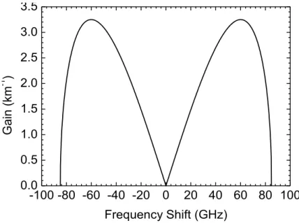
The spectrum of g(Ω) is shown in Fig. 2.3 using typical parameters of a standard SMF:
β2=-22.8 ps2km-1, γ=1.3 W-1km-1 and P0=1.25 W (same parameters which were used in
section 3.4 to simulate the propagation of a pulse along the fibre).
-100 -80 -60 -40 -20 0 20 40 60 80 100 0.0 0.5 1.0 1.5 2.0 2.5 3.0 3.5 G ai n (km -1 ) Frequency Shift (GHz)
Fig. 2.3 Gain spectrum induced by MI using the parameters of a typical SMF.
This process can be thought off as a degenerate FWM process, where two photons from the central angular frequency ω0 are destroyed to create two photons of angular
frequency ω0-Ω and ω0+Ω. In this case, the process is phase-matched by the nonlinear
phase (P0.γz) which is introduced by SPM.
In the time domain, as a result of MI, a CW will be converted into a periodic pulse train with a period [9]: T 2 2 c 2 2 (2P0) . This can be used to generate stable ultra-short pulses with a periodicity that can be tuned by the CW power (P0).


![Fig. 3.5 ϕOTDR setup used for intrusion sensing in fields tests (adapted from ref. [32])](https://thumb-eu.123doks.com/thumbv2/123dok_br/15800059.1079177/64.892.227.674.353.787/fig-ϕotdr-setup-intrusion-sensing-fields-tests-adapted.webp)