The Parameters affecting on Raman Gain and Bandwidth for Distributed Multi-Raman
Amplifier
Fathy M. Mustafa1, Ashraf A. Khalaf2 and F. A. El-Geldawy3
1 Electronics and Communications Engineering Department, Bani-suef University, Egypt
2 Electronics and Communications Engineering Department, Mina University, Egypt
3 Electronics and Communications Engineering Department, Mina University, Egypt
Abstract
Due to the benefits of Raman amplifier for Long-Haul UW-WDM Optical Communications Systems, we interest in this paper to investigate the parameters affecting on Raman gain and bandwidth, and also we are analyzed four and eight Raman pumping of special pump power and pumping wavelengths to show the effect of this parameters on gain and bandwidth. The model equations are numerically handled and processed via specially cast software (Matlab). The gain is computed over the spectral optical wavelengths (1.45µm ≤λ signal≤ 1.65µm).
Keywords: Raman amplifier, Distributed multi-pumping Raman amplifier (DMRA), Raman gain, pumping power and wavelength, ultra wide-wavelength division multiplexing (UW-WDM).
1. Introduction
There are mainly three reasons for the interest in Raman amplifier. First its capability to provide distributed amplification second is the possibility to provide gain at any wavelength by selecting appropriate pump wavelengths, and the third is the fact that the amplification bandwidth may be broadened simply by adding more pump wavelengths. An important feature of the Raman amplification process is that amplification is achievable at any wavelength by choosing the pump wavelength in accordance with the signal wavelength [1].
The term distributed amplification refers to the method of cancellation of the intrinsic fiber loss. the loss in distributed amplifiers is counterbalanced at every point along the transmission fiber in an ideal distributed amplifier [1].
In the late eighties, Raman amplification was perceived as the way to overcome attenuation in optical fibers and research on long haul transmission was carried out demonstrating transmission over several thousand kilometers using distributed Raman amplification. However, with the development and
commercialization of erbium-doped fiber amplifiers through the early nineties, work on distributed Raman amplifiers was abandoned because of its poor pump power efficiency when compared to erbium-doped fiber amplifiers (EDFAs). In the mid-nineties, high-power pump lasers became available and in the years following, several system experiments demonstrated the benefits of distributed Raman amplification including repeater-less undersea experiments, high-capacity terrestrial as well as submarine systems transmission experiments, shorter span single-channel systems including 320 Gbit/s pseudo linear transmissions, and in soliton systems [1].
distributed Raman amplifiers improved noise performance because of amplification at any wavelength controlled simply by selecting the appropriate pump wavelength, extended bandwidth achieved by using multiple pumps whencompared to amplification using EDFAs, and finally control of the spectral shape of the gain and the noise figure,which may be adjusted by combining and controlling the wavelength and power among multiplepumps [1]. The use of distributed Raman amplification has already been demonstrated in ultra-high-capacity optical communication systems as the enabling method to transmit 40Gbit/s per channel in a wavelength-division-multiplexed transmission system [1].
yielding excellent system performance for 10 Gb/s ULH and 40Gb/s signals and ULH transmission over 2500 km in a hybrid configuration [2]. It was shown how that amplification scheme provides enough gain to handle discrete losses from optical add/drop multiplexers (OADMs) inserted along the transmission. A comprehensive experimental investigation of an all-Raman ultra wide signal-band transmission system for both 10 and 40 Gb/s line rates was done [2].
The most important feature of Raman-gain spectrum is that the peak-gain wavelength only depends on the pump wavelength. The peak-gain wavelength for each pump still exists although the total gain spectrum of a multi-pumped fiber Raman amplifier (FRA) is the comprehensive result of all pumps [3].
Two critical merits of distributed Raman amplifier (DRA) are the low noise and the arbitrary gain band. Experiments show that 2.5 Gb/s system could be up graded to 10Gb/s by only adding a Raman amplifier [4].
Raman amplifiers pumped at multiple wavelengths draw significant attention in high-speed long-haul WDM transmission, for example, because of their wideband flat-gain profile (100nm with 12 channel-WDM pumping) and superior signal-to-noise ratio (SNR) performance. However, they require numbers of high power pump lasers to achieve high-gain and high bandwidth which makes it very expensive at the initial deployment stage where the WDM bandwidth is not in full use. While modular band-by-band and high upgrade like EDFA-based WDM systems reduces system introduction cost very much, in which either C or L-band EDFAs can be added later when a new bandwidth becomes needed. However, such modular addition of amplifiers is not possible for a DRA in which a transmission fiber is shared as common-gain medium. Neglecting nonlinear pump interaction or saturation WDM-pumped Raman amplifier gain can be approximated as the linear superposition of Raman gains induced by each pump laser [5].
Currently, RFAs are the only silica-fiber based technology that can extend the amplification bandwidth to the S band while providing performance and reliability comparable with those of EDFAs. However, the noise figure remains high compared to that of the C and L bands [6].
In this paper, the parameters affecting on Raman gain coefficient and Raman differential gain and
bandwidth are processed through a numerical solution of the mathematical model.
2. Mathematical Model
In the present section, we cast the basic model and the governing equation to process N-Raman amplifiers in a cascaded form of special pumping powers Pr1, Pr2, Pr3, Pr4, ……., PrN and corresponding pumping wavelengths λr1, λr2, λr3, λr4, ……., λrN. The map of δ-g is as shown in Fig. 1, where δ is the Raman shift and g is the Raman differential gain coefficient; both were cast based on [7-11] as:
,
Figure 1 Gain, g, of multi-pump Raman amplifier.
The map of δ–g shown in Fig. 1 describes the basic model. This section depends on the position of the gain of each amplifier with wavelength, where the gain of each amplifier consists of three parts (three equations). A special software program is used to indicate the position of δo,i or λo,i and studying the total gain of the amplifiers. In this case, the basic model depends on using more than one amplifier which is put in a cascaded form to increase the bandwidth of the amplifier to multiplexing more signals in the transmission system. The overall amplifier bandwidth increases and the gain flatness improved depend on the position of each amplifier corresponding to other amplifiers. This is achieved by more trials of changing of δo,i or λ o,i for each amplifier.
The general equations representing the Raman gain in the three regions are respectively [11].
, ,
Where
, , , ,
Where . / and
. , .
, , ,
. , .
, , ,
And
, е . ,
∆λ = λ2 – λ1 = 15 nm = (fixed value)
. ,
, ,
Where
, . , ,
With
. , .
, , ,
With 1 cm-1 = 30 GHz [12], where λo,i indicates the offset wavelength and λr,i indicates the pumping wavelength of each amplifier. These wavelengths are then used to indicate δo,i for each amplifier.
, , , ,
Where, . / is the differential Raman gain constant (of pure SiO2 at λ = 1.34 µm),
and
. , .
, , ,
. , .
, , ,
And
, е . , , ,
∆λ = λ2 – λ1 = 16 nm = (fixed value)
. ,
Where, λr is Raman pump wavelength and λo ≥ 1.35um.
The shift δo,i is the Raman shift that indicates the position of each amplifier. By changing this position, the total bandwidth and the flatness of the amplifier are changed. We are interested in obtaining a large bandwidth with flatness by more trials of changing δo.i or λo,i. In this case, one uses δ > δr or λ > λr and δo≥
δr or λo≥λr, where λr is Raman pump wavelength. Raman differential gain constant, g, and the effective core area, A, are defined as [8]:
.
,
Where
. √∆
.
,
Where, λr is the pump wavelength, Ws and Wr are the mode field radii of two light waves coupled with each other with W=Ws at λ= λs and W=Wr at λ= λr and ∆ is the relative refractive index difference, n1 is refractive index of the core and NA is the numerical aperture.
Neglecting the cross coupling among the signal channels, one has the differential equation governing the signal propagation for N-channels Raman pumping [9]:
Where, Si is s Assume
The tota total gai pumping variables waveleng Raman p Define g Then, the The thre functions 3. Simul The gain Raman results s Raman amplifier waveleng and als broadene pumps a and the refractive In this pa four and and pum
i = 1,2,3,…… signal power
the R.H.S of
l gain coeffic n coefficient g. It is clear t s {signal wa
gth, relative power}. This
ci , the total g
e total differe
ee gain coef s of the propa
lation Resul n and bandw
amplifier ( show that th
gain and ba r change
gths and rel o the band ed by mean and according gain is incre e index differ aper, we disc d eight Rama mping power
…..N, M is th r and PRj is f equation (2
,
cient in m¯¹ w t of the ith s that gti is a f avelength, fi e refractive term can be
,
gain coefficie
,
ential gain, gd
,
fficients gdi, agation dista
ts and Discu width for dis DMRA) is he paramete andwidth, wh according lative refract dwidth, ∆λr, ns of increa g to the posit eases with i rence. cuss two diffe
an pumping are shown
he number of s the pump 0) equals gti
which repres signal due to
function of th iber radius, e index dif
written in the
ent per watt, a
di, is:
gci and gti a ance.
ussions stributed mu
optimized. ers effecting here the gain
to the p tive index di
can be e sing the nu tion of each a
ncrease the
erent models optical wave in the table
f pumps, power. , as:
ents the o the N-he set of
Raman fference, e form: as are also ulti-pump Optimal on the n of the pumping fference evidently mber of amplifier relative s namely elengths I and II
respectively watt. The th displayed fo
3.1 Effect o on Raman Figure 2, ex and relative is plotted fo that Raman index differe
Figure 2 Rama
Then for R gain must b refractive in source sui wavelength this not requ So, the re materials m optical amp
3.2 Effect
Gain
If pumping decreases. Raman gain µm. This fig refractive wavelengths to 1.55 µm. to avoid noiy, where the hree gain co or each case
of Relative Gain xplains the r e refractive in or special pum n gain increas
ence.
an gain versus re
aman amplif be design or ndex differen
table wave increased w uired in desig lative refrac must be take
lifiers.
of Pumping
g wavelengt Figure 3, e ns, g m/w, gure is plotted
index dif s for optical This range is se and losse
sum of pump oefficients gd
.
Refractive I
relation betw dex differenc mping wavel ses with the
elative refractive
fier to get a r used fiber nce and als length's wh we get losses
gn.
ctive index d en in accou
g Waveleng
hs increase explains the and pumping d at different fference, w
signals is in s suitable for es.
ping power is di, gci, and g
Index Differ
ween Raman ce, and this f engths. It's f relative refra
index difference.
mplifier with with high rel so used pum here if pum s is increases
difference of unt in desig
gth on Ram
es, Raman relation betw g wavelengt values of re where pum
a range from r Raman amp
s one ti are
Figure 3,
Where if losses a signal tr need am problem differenc waveleng Then, an pumping design to
3.3 Rela
Relative
The mod relative r Figure 4 with rela pumpingFigure 4
Variation of Ram
f pumping wa nd noise is la ransmitted ( mplifier with must be in ce to get bala
gth.
ny source ha g power mu o obtain suita
ation betw
e Refractive
de field radii refractive ind , explains the ative refract g wavelength4, Variation of m inde
man gain, g, with um
avelength ab arge and this (this is disa h high gain ncrease relat
ance betwee
aving a pump ust be suita able gain and
ween Mode
e Index Diff
are inverselex difference e variation of ive Index d s.
mode field radii ex difference , ∆
pumping wavele
bove 1.55 µm s not required advantages)
, so to av tive refractiv en gain and p
ping wavelen able for the d bandwidth.
Field Rad
ference
y proportiona e.
f the mode fi ifference at
with relative re
∆%
ength, λr,
m we get d for the but we void this
ve index pumping
ngth and e choice
dii and
al to the
ield radii special
efractive
we get if rel the mode aperture in increases in signal when fibers this pumping wa
3.4 Relati
Pumping W
The mode f wavelengths special va difference i Then, one c pumping w depend on tFigure 5
If pumping increase so pumping w difference w the mode fie
3.5 Relati
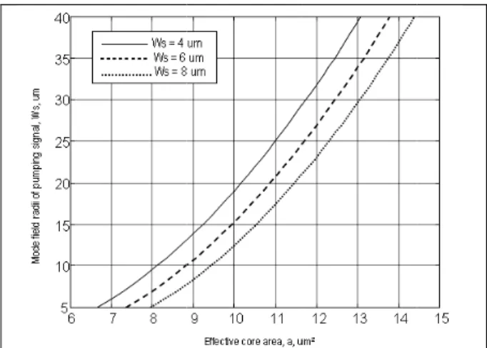
Effective C
Figure 6, e radii of pum where the m core area.This curve radii of the effective co be taking in
lative refracti field radii d ncreases an n design, to n you are co
achieved b avelength's.
on betwee
Wavelength
field radii are s. Figure 5 lues of th in the wave can get the R wavelengthsthe relative re
5, Variation of m wa
wavelength o, in design wavelength where, if rela
eld radii decr
on betwee
Core Area
explains the mping signal,mode field rad
is plotted at signal, ws. T ore area affe to account.
ive index diff decreases bu
nd we nee o avoid losse
oupling betw by using so
en Mode F
h
e proportiona 5, explains e relative elength range Raman gain w and mode efractive inde
mode field radii v avelengths.
increase the we must tak and also tive index di reases.
en Mode F
relation betw wr, andeffec dii increases
special valu This result is ects in Rama
ference incre ut the nume ed the two
es in transm ween the diff
ources with
Field Radii
al to the pum this relatio refractive i e 1.4 – 1.5 which depend
filed radii w ex difference
versus pumping
e mode field ke in accoun
relative i fference incr
Field Radii
ween mode ctive core are
with the effe
ues of mode useful where an gain and
eases erical are mitted
ferent high
and
mping on at
index µm. ds on which e.
g
radii nt the index rease
and
field ea, A, ective
Figure 6
Figure 7 radii of s the mod area exp curve is pumping
Figure
Then fro area of t get mo advantag fibers to between
3.6 Rela
Relative
Figure 8 core are curve is clear th (exponen6, Variation of m with effec
7, displays t signal, ws, an
e field radii ponentially ac
plotted for sp g signal, wr .
7, Variation of effecti
om figures 6 the fiber (diam ode field r
ges for cou get high effi different join
ation betwe
e Refractive
8, shows the ea and the replotted at sp hat the ef
ntially) with ∆
mode field radii ctive core area
he relation ndeffective c
increases wi ccording to a pecial value
mode field rad ve core area, A
and 7, we meter of the radii increas
pling signals iciency to tra nts and differ
een Effectiv
e Index Diff
e relation be elative index pecial pumpin ffective core∆.
of pumping sig , A, µm2.
between mo core area, A ith the effect above equati of mode field
ii of signal, ws, v A, µm2
get for incre core of the f se and th s between ansmitted the
rent fibers.
ve Core Are
ference
etween the e x difference,ng waveleng e area de
gnal, wr,
ode field A, where,
tive core on. This d radii of
versus
ease the fiber) we is also different e signals
ea and
effective
∆. This gths. It is ecreases
Since Rama index differ result is v affecting in gain.
Figure 8,
In design to source with (1.45µm ≤λ for used fibe the losses between dif
3.7 Effect optical amp the Gain In this case four and eig and pumpin the amplifie is improved
3.7.1 Numb Ta
λ1 – λo = f
λ r λo
1.4 1.43
1.42 1.45
1.467 1.49
1.5 1.5
an gain is pro rence and e very useful Raman gain
Variation of eff relative ind
o avoid this h high pum
λ signal≤ 1.55 er with effect in signals w fferent fibers.
of Numbe plifier) on th
e we discuss ght Raman ng powers in ers increased with increas
ber of optica able I Num
. fixed (0.0962
o λ1
32 1.52829
52 1.54829
99 1.59529
52 1.61629
oportional to effective core
to indicate to obtain a m
fective core are dex difference,
disadvantag mping wave
µm) because tive core area which occur .
r of pump he Gain and
s two differen pumping opt n this case w d and the fla sing the numb
al amplifier = ber of amplif
294798) and
94799 1.54
94799 1.56
94799 1.61
94799 1.63
relative refra e area, then the param maximum an
a, A, um2 versu
∆.
ge must be elength in r e of it is impo
a is large to a s when cou
ing (numbe d the Flatnes
nt models na tical wavelen we get the ga tness of the ber of pumpi
= 4 fiers = 4
,
λ2 – λ1 = 16
λ2 P
4294799
4294799 0
1294799 0
2294799
active n this
eters nd flat
us
used range ortant avoid upling
er of ss of
amely ngths ain of gain ng.
nm
Pp(W)
Differen Figure 9 waveleng refractive increase
Fig
We note the first at 1.54 exponen optical a range 1.4 In this c where λ1 µm (for a
Gain coe The gai against w values o
Figure 10
We note increase
ntial gain , displays the gth, λ, at d e index differ es, Raman ga
gure 9, Variation
e that Raman pumping wa
µm, then ntially tended amplifiers and
45 µm to 1.6 case we obt 1t = 1.49 µm all amplifiers)
efficient per n coefficient wavelength f relative refr
, Gain coefficient
e that gain e from the fir
e differential different val rence. If rela ains increase
n of differential wavelength.
n gain is sta avelength to the gain is d to zero at 1
d optical sig 65 µm.
ained, total (for all ampl ).
r unit watt t/unit watt, ∑
is shown in ractive index
ts per unit watt ag
coefficient/u rst pumping w
Raman gain ues of the ative index di es.
Raman gain w
arts to increa reach to pea s start to d
1.65 µm. Bec nals are ope
bandwidth = lifiers) and λ2
∑ gi / Ai, Fig. 10, at difference.
gainst wavelengt
nit watt is s wavelength t
n, g, with relative fference
with
ase from ak value decrease cause of erated in
=100nm, 2t = 1.59
m¯¹ W¯¹ different
th.
starts to to reach
to peak val decrease ex
In this c control in g effective c difference, powers. So design. Wh design. In this case where λ1t = µm (for all a
In this ca where λ1t = µm (for all a
Total gain c Figure 11, coefficient w of 100 nm is
Figure 11
By similar w increase fro to peak va decrease e Gain in this effective co Where pum increase so high pumpin
lue at 1.54 xponentially t case more t gain coeffici core area, pumping these param here each
e we obtaine 1.49 µm (fo amplifiers).
ase we obtai 1.51 µm (fo amplifiers).
coefficient displays the with wavelen
s obtained.
, Variation of tota
we note the t om the first p
alue at 1.54 exponentially
s case is a re area and r mping power Raman amp ng powers.
µm, then the tended to ze than one pa ent per uni relative
wavelengths meters take in
parameter
ed, total ban r all amplifie
ned, total ba r all amplifie
e variation o gth. In this c
al gain coefficient
total gain coe pumping wav 4 µm, the tended to affected by p relative index rs increase plifiers is use
e gain is sta ro at 1.65 µm arameter ca
t watt such refractive i s and pum
n account fo can effecte
ndwidth =10 rs) and λ2t =
andwidth =11 rs) and λ2t =
of the total case, a bandw
t with wavelength
efficient is sta velength to r
gain is sta zero at 1.6 pumping pow x difference.
the total ga ed to sources
art to m.
n be that index mping r any ed in
00nm, 1.59
0nm, 1.62
gain width
h.
art to reach art to 65µm.
wers,
3.7.2 Nu
λ1 – λo
λ r
1.41
1.44 1
1.45 1
1.46 1
1.47 1
1.48 1
1.49 1
1.5 1
The diffe per unit and 13, this case value in
Figure 12
Figure
umber of opt Table II N o = fixed (0.09
λo
1.41 1.503
1.444 1.537
1.455 1.548
1.466 1.559
1.478 1.571
1.489 1.582
1.501 1.594 1.512 1.605
erential Ram watt are dis while the tot e, a 110 nm this case at 1
, Variation of diffe
e 13, Gain coeffic
tical amplifie Number of am 93262399) a
λ1
3262399 1.
7262399 1.
8262399 1.
9262399 1.
1262399 1.
2262399 1.
4262399 1. 5262399 1.
man gain and splayed, resp al gain is dis m bandwidth 1.55 µm for t
erential Raman g
cients per unit wa er = 8 mplifiers = 8
nd λ2 – λ1 =
λ2
519262399 553262399 564262399 575262399 587262399 598262399 610262399 621262399
d the gain co pectively, in splayed in Fig h is obtaine the different g
gain with wavelen
att against wavele 16 nm
Pp(W)
0.14 0.12 0.14 0.10 0.14 0.12 0.11 0.13
oefficient Figs. 12 g. 14. In d. Peak gain.
ngth.
ength.
Figure 1
4. Conclus The bandw Raman am variables {λ constant ga pumping po obtained ba for use 4 an of the obtai following co
Table of ma
No of optica amplifiers
4
8
From table w 1- If numb
gains in 2- If relativ Raman 3- Also, f differen 4- Bandwi value o amplifie number is equa amplifie 110 nm and ga
14, Variation of to
ion
width and t plifier (MDRA
λs, λr, ∆, the ain interval, ower and ef andwidth and nd 8 optical R
ned results, omparison tab
aximum gain
al g
2.432 1.824 1.216 5.057 3.793 2.528
we conclude ber of optical ncrease.
ve index diffe gain is incre for each c ce increases dth, flatness of the gain ers correspo
r of amplifier l to 100 nm er is four, but m for number ains in case
otal gain coefficie
he gain of A) is effecte e locations number of ffective core
gain at diffe Raman ampl in two case ble.
and bandwid
g max
26 × 10-13
45 × 10-13
63 × 10-13
77 × 10-13
33 × 10-13
89 × 10-13
e that:
amplifiers in
erence increa ease.
case only i s, Raman gai s of the gai depends on onding to e
rs where, in despite the n t case 2 band r of optical a e 2 is max
ent with waveleng
multi-distrib ed by the s
of the maxi optical amp area}. We rent value of ifiers. A sum s, is found in
dth for two ca ∆ % BW(n
0.8 0.6 0.4
10
0.8 0.6 0.4
11
ncreases, Ra
ase then we
f relative i in is increase n and maxi n the positio
ach other's case1 bandw number of op dwidth is equ amplifiers is
imum and gth.
buted set of
mum plifier, have f ∆ % mary n the
ases.
nm)
0
0
aman
gets
index e.
mum on of
flatness than in case 1, because of number of optical amplifiers is large.
5. References
[1] C. Headley, G. P. Agrawal "Raman Amplification in Fiber Optical Communication Systems", Elsevier Inc. 2005.
[2] D. F. Grosz, A. Agarawal, S. Banerje, D. N. Maywar, and A. P. Kung, "All-Raman Ultra Long-Haul Signal-Wideband DWDM Transmission Systems with OADM Capability", J. Lightwave Technol., Vol. 22, No. 2, pp. 423-432, 2004. [3] P. Xiao. O. Zeng, J. Huang, and J. Liu, "A New
Optimal Algorithm for Multi-Pumping Sources of Distributed Fiber Raman Amplifier," IEEE Photonics Technol. Lett., Vol. 15, No.2, pp. 206-208, 2003.
[4] X. Liu and B. Lee, "A Fast Stable Method for Raman Amplifier Propagation Equation," Optics Express, Vol. 11, No. 18, pp. 2163-2176, 2003.
[5] N. Kikuchi, "Novel In-Service Wavelength-Based Upgrade Scheme for Fiber Raman Amplifier, "IEEE Photonics Technol. Lett., Vol. 15, No. 1, pp. 27-29, 2003.
[6] Y. Cao and M. Raja, "Gain-Flattened Ultra-Wideband Fiber Amplifiers," Opt. Eng., Vol. 42, No. 12, pp. 4447-4451, 2003.
[7] M. S. Kao and J. Wu, "Signal Light Amplification by Stimulated Raman Scattering in an N-Channel WDM Optical Communication System", J. Lightwave Technol., Vol.7, No. 9, pp. 1290-1299, 1989.
[8] T. Nakashima, S. Seikai, N. Nakazawa, and Y. Negishi, "Theoretical Limit of Repeater Spacing in Optical Transmission Line Utilizing Raman Amplification," J. Lightwave Technol., Vol. LT-4, No. 8, pp. 1267-1272, 1986.
[9] Y. Aoki, "Properties of Fiber Raman Amplifiers and Their Applicability to Digital Optical Communication Systems," J. Lightwave Technol., Vol. 6 No. 7, pp. 1227-1239, 1988.
[10] W. Jiang and P. Ye., "Crosstalk in Raman Amplification for WDM Systems," J. Lightwave Technol., Vol. 7, No. 9, pp. 1407-1411, 1989.
[11] A. A. Mohammed, "All Broadband Raman Amplifiers for Long-Haul UW-WDM Optical
Communication Systems," Bulletin of Faculty of Electronic Engineering, Menouf, 32951, Egypt, 2004.
[12] A. Yariv, Optical Electronics in Modern Communications, 5th ed., Oxford Univ. Press, 1997.
Fathy M. Mustafa received the B.Sc. degree in Electronics and communications department with honors from the Faculty of Engineering, Fayoum University, Fayoum, Egypt, in 2003. He is currently working a research assistant in Electronics and communications department at Bani-suef University. He is earned the M.Sc degree in Electronics and communication engineering in 2007 from Arab Academy for Science and Technology & Maritime Transport College of Engineering and Technology, Alexandria, Egypt. He is joined the PhD program in Mina university in 2011. Her areas of interest include optical communications, optical amplifiers.
Ashraf A. Khalaf: received his B.Sc. and M.Sc. degrees in electrical engineering from Minia university, Egypt, in 1989 and 1994 respectively. He received his Ph.D in electrical engineering from Graduate School of Natural Science and Technology, Kanazawa university, Japan in 2000. He works at electronics and communications engineering Department, Minia University. He is a member of IEEE since 12 years.