RESIDUAL STRESSES ANALYSIS IN PLASMA DRESSED WELDED JOINTS ˗ A SIMPLIFIED FINITE ELEMENT APPROACH
A. L. Ramalho 1, J. A. M. Ferreira 2 and C. M. Branco 3
1
ESTCB, Instituto Politécnico de Castelo Branco, 6000-767 Castelo Branco, Portugal E-mail: [email protected]
2 CEMUC, Faculdade de Ciências e Tecnologia da Universidade de Coimbra,
Rua Luís Reis Santos, Pinhal de Marrocos, 3030-788 Coimbra, Portugal. E-mail: [email protected]
3 ICEMS, DEM, IST, Avenida Rovisco Pais, 1096 Lisboa Codex, Portugal
ABSTRACT
The presence of residual stresses in a structure influences his behaviour. Fatigue strength of welded joints is significantly influenced by the presence of residual stresses, of flaws and notch sharpness at the weld toe. Plasma dressing at the weld toe is frequently used to remove flaws and to lessen the notch sharpness at the weld toe. With this re-melt, the stress field in the weld toe is also profoundly modified. The Finite Element Method (FEM) proves to be effective to simulate the stress fields generated by welding. The simplified two-dimensional models (2D) are efficient in this estimation. This paper presents a 2D finite element model to predict the residual stresses generated by Plasma dressing at the weld toe of a T-joint. The welded T-joints are made in St 52-3 steel, are obtained by covered electrode process and improved with plasma dressing. The analysis was developed with the MSC.Marc finite element code. The estimated stress field is validated with experimental stress results obtained using X-ray diffraction.
KEYWORDS:Residual Stresses, Welding Simulation, FEM.
1. INTRODUCTION
Residual stresses are present in many manufactured components due to localised plastic deformation originated by thermo-mechanical processes. Its presence affects the mechanical behaviour of such components, and its effect depends on their magnitude, sign and distribution and of their interaction with the stresses originated by the subsequent service loads. With regard to the fatigue behaviour, the residual tensile stresses reduce the fatigue life while the compression ones increase it [1].
Fatigue life of welded joints is influenced by pre-existing cracks in the weld toe inherent to the welding techniques. Such defects, the stress concentration induced in the weld toe section and the presence of tensile residual stresses of the magnitude of the yield strength, produced by welding, explains the relatively poor fatigue strengths of welded joints [2].
Post-weld improvement techniques increases fatigue life of the welded joints by one, or several, of the fallowing effects: removal of the weld defects; reduction of the stress concentration at the weld toe; relief of the tensile residual stresses at the weld toe or its replacement by compression ones. Techniques such as: tungsten inert gas (TIG) and plasma dressing, burr grinding, needle, shot and hammer peening have been studied in last decades and reported in numerous papers [3-7].
The benefits obtained by the dressing techniques (TIG or plasma) are attributed to the removal of flaws and the smoothing of the weld toe radius [2,7]. The effect of the dressing techniques in modifying the residual stress field in the weld toe section, has been reported [8,9].
Three-dimensional (3D) finite element welding simulations are frequently used to predict residual stresses and distortion in welded structures [10,11]. However, the 3D simulation increases the complexity of analysis, requires sophisticated hardware resources and a high processing time. These resources are not always available in order to accurately predict the residual stresses at the weld toe. Furthermore, when the welding speed is great enough and the study scope does not addresses edge effects, 2D finite element approach in the midsection of the weld proves to be efficient to predict the residual stress field for mechanical fracture crack growth analysis purposes [10-15].
A two-dimensional finite element welding simulation procedure was developed by the authors [16] in order to predict the residual stresses field induced by TIG dressing technique. This procedure is now adapted to the plasma dressing technique.
2. MATERIALS AND EXPERIMENTAL PROCEDURE
The base material used in this study was a medium strength steel, St 52-3 DIN 17100, in the form of plates with 12.5mm thickness. The welds were made by covered electrode process with weld metal in overmatching condition.
The mechanical properties of the based material, at room temperature, were obtained using a tension specimen with 8 mm diameter, according with the European standard EN 10 002-1. The tests were carried out in a servo-hydraulic machine (Instron model 1341). The load rate was constant and the strain was measured using a strain gauge with 50 mm length mounted directly on the specimen. The machine software calculates the strain and stress.
The mechanical properties of the base material at high temperature were obtained using a tension specimen with 6mm diameter according with Portuguese standard NP EN 10 002-5. The tests were carried out also in the servo-hydraulic Instron machine coupling a furnace and using an axial quartz gauge, model Instron-A1387-1023, directly coupled in the specimen. The machine software calculates the strain and stress.
The accurate material properties as function of temperature are generally difficult to obtain at the high temperature region. However, these properties were essential to the accuracy of the welding simulation. In this study the mechanical properties obtained in the tests at high temperature were used to refine the model of the thermo mechanical behaviour of the base material adapted from similar materials [13,14,17].
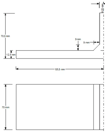
T-joints weld specimens were produced from main plates with 12.5 mm thickness and low penetration fillet welded with an attachment of equal thickness. From this plate, specimens with 70 mm width and 270 mm length were cut. The weld leg length presented a medium value of 9 mm. The specimens were made with the geometry shown in Fig. 1.
Post-weld improvement and rehabilitation treatment of weld T-joints with fatigue cracks at the weld toe were performed by plasma dressing technique, using the programmable welding equipment ESAB Seamtech ED5 type with the parameters indicated in Table 1.
Experimental measures of the residual stresses at the surface of the specimens in the proximity of the weld toe were obtained using the X-ray diffraction technique. Were used the Elphyse diffractometer Set X model. More details of the experimental procedures, materials and used equipment and their control parameters can be obtained in reference [15].
Figure 1. Geometry of the specimens.
Table 1. Principal plasma dressing parameters Argon flux 13.0 liters/minute Current intensity 200 A
Tension DC 30 V
Linear rate 2.47 mm/s
3. WELDING SIMULATION
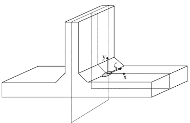
The simulation was performed in a Personal Computer with a Pentium II processor and the Windows NT operating system, using a 2D finite element model developed in the finite element software MSC.Marc. The 2D analysis was done in the plane normal to welding direction in the middle section of the specimen as shown in the Fig. 2. The heat flow in the welding direction was neglected. This simplification is reasonable when the arc speed is high enough [11,12]. 2D models on the plane perpendicular to the welding direction produce good residual stress approximations for continuous welds [10-14,17-21].
Given the heat generated by the welding process, the influence of the deformation and the thermodynamic effects of microstructural changes were considered of despicable effect in the heat flow analysis. The simulation was carried out in a sequentially coupled analysis: a thermal analysis was followed by a mechanical analysis. The temperature distributions resulting from the thermal analysis were used as loads in the elastic–plastic mechanical analysis. Similar
assumptions were done by others investigators for identical purposes [13,14,21].
Figure 2. Middle section of the specimen and local referential used for the 2D simulation.
In the simulation were assumed symmetry conditions for the middle vertical plane parallel to the welding direction, represented in Fig.2.
The material of the weld metal, heat affected zone and the base metal were assumed to be the same [21].
3.1. Thermal analysis
A 2D transient non-linear heat flow finite element analysis was carried out at the middle plane perpendicular to the welding direction. The used finite element mesh is presented in Fig. 3.
The mesh consists of 828 nodes and 766 elements. The Marc element type 39 was used. He’s a four-node, isoparametric, heat transfer quadrilateral, linear element. This element uses bilinear interpolation functions, the thermal gradients are constant throughout the element. Adiabatic boundary conditions were considered in the symmetry plane. In all the others surfaces convective-radiative conditions were used [18].
For the convective and radiative boundary conditions, a combined heat transfer coefficient was calculated using the relationship, from [22]:
h=24.1x10⁻⁴T1.61 (1)
where T unit is ºC, h unit is Wm-2 ºC-1 and is the emissivity of the surface of the body. From [23] a value of 0.9 was assumed for .
This boundary condition, where a heat transfer coefficient depends on the temperature does not exist in the standard tools available in the software MSC.Marc [24] However, the vast majority of the general purpose finite element software available provides the user
subroutine resource. That constitutes one of the real
strengths of this software, allowing to the user the use of their own subroutines instead of several existing in the program. This feature provides wide latitude for solving nonstandard problems. The new user subroutines must be compiled and linked with the standard finite element software for the new capabilities are available. This nonstandard boundary condition was developed through a Visual Fortran programmed subroutine and was made available in MSC.Marc through the user subroutine
x
y
ZOOM
FILM [25]. The subroutine is available in reference [15].
The thermal properties as function of temperature – thermal conductivity, K, and the specific heat, Cp – were obtained from references [13,23] from similar materials. To take account the influence of convection, caused by the fluid flow in the weld pool, the thermal conductivity was artificially increased for temperatures above the melting point [11,14]. More details of these used properties as function of temperature can be obtained in reference [15].
A latent heat of fusion of 247 kJkg-1 was assumed to be absorbed/released between the solidus and liquidus temperatures. These temperatures were assumed equal to 1470°C and 1520°C respectively.
A constant density of 7860 kgm-3 was assumed.
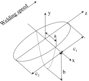
The heat generated by the arc welding was inputted using the double ellipsoid heat source model [18]. In the ellipsoid model a Gaussian distribution of the power density in an ellipsoid with centre at point (0,0,0) and semi-axes a, b and c, parallel to the coordinate axes x, y, ξ, as indicated in Fig.2, was considered.
With this model, the temperature gradient in the front of the heat source was not as steep as expected, and in the rear the gradient was steeper than expected. To overcome this limitation in the double ellipsoid heat
source model, two semi-ellipsoidal sources were
combined as shown in Fig. 4.
Figure 4. Geometry of the double ellipsoid heat source model.
The power density distribution in this model is done by
)
2
(
3
6
)
,
,
,
(
e
3x2/a2e
3y2/b2e
3z v( t)/c2abc
Q
f
t
z
y
x
q
where Q=ηVI, η is the efficiency of the weld process,
v is the arc speed, τ is a lag factor to define the position of source at t=0 and ξ = z + v(τ – t). For the frontal semi-ellipsoid f=0.6 and c=c1=a. For the rear
semi-ellipsoid f=1.4 and c=c2=4a.
The double ellipsoid heat source model can be adapted to a 2D finite element model through an algorithm presented in references [11, 18].
This body flux for a 2D finite element model, where a specific heat input depends on the coordinates of the elements and the time, does not exist in the standard tools available in the software MSC.Marc[24]. This nonstandard body flux was developed through a Visual Fortran programmed subroutine and was made available in MSC.Marc through the user subroutine FLUX [25]. The subroutine is available in reference [15].
3.2. Mechanical analysis
A 2D generalized plane strain quasi-static finite element analysis was carried out with the same mesh that was used in the thermal analysis.
The Marc element type 11 was used. He’s a four-node, isoparametric, plane strain quadrilateral and linear element. This element uses bilinear interpolation functions and the strains are constant throughout the element.
In the symmetry plane, horizontal displacement restriction was performed. In the lower right node a spring, with despicable stiffness, was added, in order to restrict the rigid body movement.
The material was modelled as elasto-plastic, with a rate independent von Mises plasticity, using a combined hardening rule.
Was not considered the effect of microstructures changes on the residual stresses generation [11,17,19-21].
The temperature-dependent mechanical properties were obtained from similar materials [13,14,17,23], and pondered in order to correlate the properties obtained in the material tests referred in section 2. More details of these used properties as function of temperature can be obtained in reference [15].
The loading was performed by gradually imposing the deformation field originated by the temperature field obtained in the preceding thermal analysis.
4. RESULTS AND DISCUSSION
4.1. Thermal analysis
The comparison between the real fusion zone and the one provided by the simulation is an accepted process for the thermal analysis validation [11,18,21].
z
z
y
x
c
1c
2b
a
W
elding
spe
ed
The fusion zone predicted by the welding simulation is in good agreement with the experimental one as shown in Fig. 6.
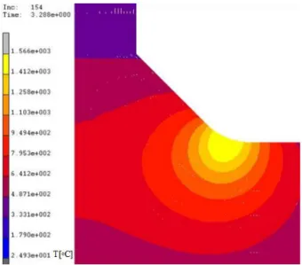
Figure 5. Experimental and predicted fusion zone. Fig. 6 presents the highest temperature field, predicted for the specimen.
Figure 6. Highest predicted temperature field.
4.2. Mechanical analysis
The longitudinal residual stress field, obtained near the weld zone, is shown in Fig. 7. At the weld region, compressive residual stresses are observed. At zones remote do the weld, tensile stresses are developed equilibrating the compressive ones of the weld zone. X-ray surface residual stresses measurements were obtained near the weld toe. These results are represented in Fig. 8 against the estimated residual stresses. A dimensionless coordinate is used to allow comparison of experimental results obtained from various specimens with different weld toe positions.
The estimated residual stresses are in good agreement with the ones obtained experimentally, allowing the validation of the numerical model for the welding simulation.
Figure 7. Predicted residual stress field.
Figure 8. Comparison between the estimated residual stresses and those obtained experimentally.
5. CONCLUSIONS
A two-step thermo mechanical finite element analysis was applied to predict residual stress field, induced by plasma dressing at the weld toe of a T-joint, using a 2D transient non-linear thermal analysis fallowed by a 2D small deformation quasi-static elasto-plastic one. Predicted and experimental surface residual stresses obtained by the X-ray diffraction method were compared and a very good agreement was obtained. The method is being applied to study the influence of the residual stress field estimated in the fatigue life of T-joints improved by dressing techniques.
REFERENCES
[1] Josefson BL, Ringsberg JW. Redistribution of stresses from manufacturing operations during service loads and their effect on fatigue life of built-up structures. Proceedings of the 15th European Conference of Fracture, Stockholm, Sweden 2004. [2] Manteghi S, Maddox SJ. Methods for Fatigue Life
Improvement of Welded Joints in Medium and High Strength Steels. IIW Doc. XIII-2006-04; 2004. [3] Huther I, Lieurade HP, Souissi R, Nussbaumer A,
Chabrolin B, Janosch JJ. Analysis of results on improved welded joints. Welding in the World 1996; 37(5): 242-266.
[4] Branco CM, Maddox SJ, Infante V, Gomes EC. Fatigue performance of TIG and plasma welds in thin sections. International Journal of Fatigue 1999; 22(6): 602-589.
[5] Dahle T. Design fatigue strength of TIG dressed welded joints in high strength steels subjected to spectrum loading. International Journal of Fatigue 1998; 20(9): 681-667.
[6] Kirkhope KJ, Bell R, Caron L, Basu RI, Ma K-T. Weld detail fatigue life improvement techniques. Part 2: application to ship structures. Marine Structures 1999; 12: 477-496.
[7] Kirkhope KJ, Bell R, Caron L, Basu RI, Ma K-T. Weld detail fatigue life improvement techniques. Part 1: review. Marine Structures 1999; 12: 447-474. [8] Ramalho AL, Ferreira JAM, Branco CM. Fatigue Behaviour of T Welded Joints Rehabilitated by Tungsten Inert Gas and Plasma Dressing. Materials and Design 2011, 32(10): 4705-4713.
[9] Martinez LL, Lin R, Wang D, Blom AF. Investigation of Residual Stresses in As-Welded and TIG-Dressed Specimens Subjected to Static/Spectrum Loading. Proceedings of the North European Engineering and Science Conference, (NESCO): Welded High-Strength Steel Structures. Stockholm, Sweden, 1997.
[10] Barsoum Z, Lundbäck A. Simplified FE welding simulation of fillet welds – 3D effects on the formation residual stresses. Engineering Failure Analysis 2009, 16: 2281–2289.
[11] Karlsson L. Thermal Stresses in welding. Thermal Stresses, Vol. I, ed. Hetnarski RB, Elsevier Science Publishers, 1986, pp. 300-389.
[12] Goldak J, Bibby M, Moore J, House, Patel B. Computer Modeling of Heat Flow in Welds. Metallurgical Transactions B 1986, 17B: 587-600.
[13] Michaleris P, DeBiccari A. A Two-Step Numerical analysis Technique Was Developed to Predict Welding-Induced Distortion and the Structural Integrity of Large and Complex Structures. Welding Research Supplement to the Welding Journal 1997, Vol. 76(4), pp. 172s-181s.
[14] Michaleris P, Sun X. Finite Element Analysis of Thermal Tensioning Techniques Mitigating Weld Buckling Distortion. Welding Research Supplement to the Welding Journal 1997, Vol 76(11), pp. 451s-457s.
[15] Ramalho AL. Prediction of fatigue strength in welded joints rehabilitated by re-melting techniques (in Portuguese). PhD Thesis, Coimbra University, Portugal, 2006.
[16] Ramalho AL, Ferreira JAM, Branco CM. Residual stresses analysis in TIG dressed welded joints. Proceedings of the 8th Portuguese Conference on Fracture 2002.
[17] Börgesson L, Lindgren L-E. Simulation of Multipass Welding With Simultaneous Computation of Material Properties. Journal of Engineering Materials and Technology 2001, 123: 106-111. [18] Goldak J, Chakravarti A, Bibby M. A New Finite
Element Model for Welding Heat Sources. Metallurgical Transactions B 1984, 15B: 299-305. [19] Lindgren L-E. Finite Element Modeling and
Simulation of Welding. Part 1: Increased Complexity. Journal of Thermal Stresses 2001, 24(2): 141-192.
[20] Lindgren L-E. Finite Element Modeling and Simulation of Welding. Part 2: Improved Material Modeling. Journal of Thermal Stresses 2001, 24(3): 195-231.
[21] Barsoum Z, Barsoum I. Residual stress effects on fatigue life of welded structures using LEFM. Engineering Failure Analysis 2009, 16(1): 449-467. [22] Rykalin RR. Energy Sources for Welding.
Houdrement Lecture, International Institute of Welding, London, 1974.
[23] The British Iron and Steel Research Association, Physical Constants of Some Commercial Steels at Elevated Temperatures. London Butterworths Scientific Publications, 1953.
[24] MARC Volume A: Theory and User Information. Version K7, MARC Analysis Research Corporation, USA, 1997.
[25] MARC Volume D: User Subroutines and Special Subroutines. Version K7, MARC Analysis Research Corporation, USA, 1997.