structures under internal pressure is cylindrical[1].
In this paper is considered only. Elastic and elastic-plastic finite element analysis is used to predict the principle stresses, effective stress results are compared with those obtained from theatrical equations in order to predict the limit and failure loads for this type of loading also the relationships between redial, hoop stresses and displacement has been used to develop a through understanding. The analysis was completed using ANAYS Version 9.0. (a finite element program for Microsoft Windows NT). The program allows pre-processing, analysis and post-processing stages to be completed within a single application. The program can be used to model a large number of situations including buckling, plastic deformation, forming and stress analysis problems.
In this study ,a thin pipe of internal radiuri 596 .9mm and of external
(
mm
ro 609 .6 objected to an internal pressure 2 / 83 . 4 mm
i
which is gradually increased to near the ultimate load that may be sustained by the pipe. The pipe is modelled as an elasto-plastic material using the Von Mises yield criterion which is normally used for metallic materials[2]. The specification of the load in several increments enables the spread of the plasticity to occur gradually and its effect on the stress distribution to be assessed. Key words: finite element analysis, elastic-plastic behavior, thin walled pipe equivalent stress, TWT.
I. Introduction
The most structures under internal pressure take cylindrical shape like as the boilers in thermal power plant, aerosol cans and gas cylinders, in this study one of the kind of this shape[3].
Elastic and elastic-plastic finite element analysis is used to predict the equivalent and principle stresses and results are compared with those obtained from theatrical equations. Theresearcher most understand mechanics properties of materials and stress-strain diagram and the principle stresses and strains because all the design of mechanical machines must have high strength to support external loads before it collapse.
II. Thin- walled pipe
A thin--walled pipe is one where the thickness of the wall is smaller than one-tenth of the radius[3] . In this study a thin petrolem pipe made from steel conveuor for oil extends from waha field to port of sidra as shown
in fig 1 of internal radius ri 596 .9mm , external radius , ro 609 .6mm
)
thickness 6.65mm,
(
mm
L 269000 subjected to an internal pressure (4. 83N/mm²) as shown In fig 2.
.
Fig 2 : thin walled pipe
2.1 Stresses in thin walled pipe
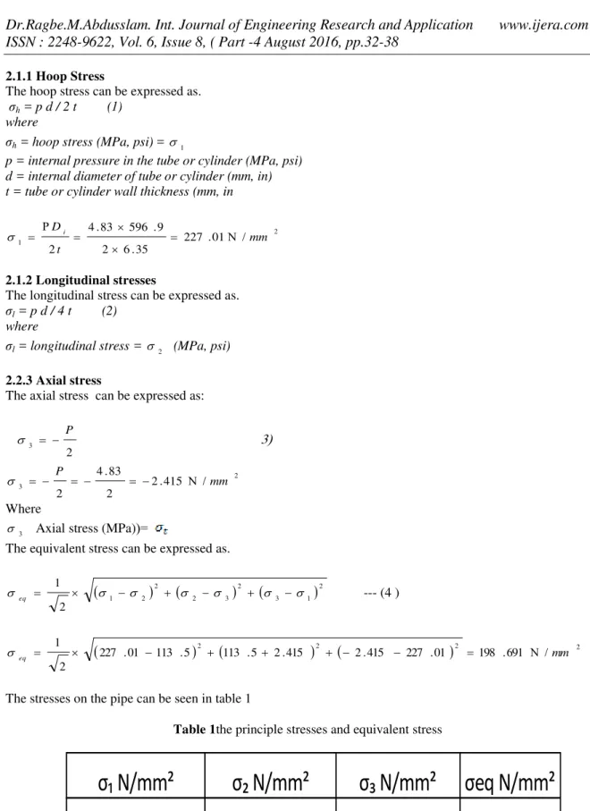
A thin walled pipe subject to an internal pressure has three principal stresses will be
The longitudinal stress can be expressed as. σl = p d / 4 t (2)
where
σl = longitudinal stress = 2 (MPa, psi)
2.2.3 Axial stress
The axial stress can be expressed as:
( 3 3 2 P 2
3 2.415 /
2 83 . 4 2 mm P Where (= 3
Axial stress (MPa)
The equivalent stress can be expressed as.
21 3 2 3 2 2 2 1 2 1
eq --- (4 )
2
2
2 2/ 691 . 198 01 . 227 415 . 2 415 . 2 5 . 113 5 . 113 01 . 227 2 1 mm
eq
The stresses on the pipe can be seen in table 1
Table 1the principle stresses and equivalent stress
m
σeq N/mm²
σ N/mm²
σ N/mm²
σ N/mm²
198.691
-2.415
113.505
227.01
Analytical solution 2.2Fig..4 Half model of the pipe section subjected to internal pressure pi
2.2.1. Finite element modeling
The TWT as shown in Fig. 4 was numerically analyzed by finite element method and the results were compared with the analytical solution. The commercially available ANSYS 9.0 finite element software was used for this purpose. Two dimensional finite element analysis (FEA) was conducted using 4-noded quadrilateral elements under plane-strain condition[2]s.
2.2.1.1 Model Geometry
Fig. 5 shows the two dimensional model geometry of the tube used for FEA. The symmetry of the tube was taken advantage of and a solid model for a half section of th e tube was created in the ANYSYS pre-processor. The same symmetry conditions
Fig 5 TWT Model used for FEA
2.2.1.2 Material properties
During FEA, an isotropic material with modulus of elasticity E = 71 GPa and Poisson’s ratio, = 0.33 was used [5]
. 2.2.1.3 Element selection and meshing
(a)
(b)
Fig.6. a) Meshed model using PLANE42 element b) magnified view of boxed area; element size is 0.5 mm
The von Mises stress distribution obtained after solution is shown in Fig. 7
Fig.7. Static loading – Nodal solution showing von Mises stress distribution at internal pressure of a) 4.83MPa
III. Comparison of the analytical and numerical results
(a)
(b)
Fig. 8. Stress versus internal pressure - comparison of the two results at inner radius a) hoop b) radial
(a)
[5]. James , M,Gere . 2004 . Mechanics of Materials . Sixth edition . Thomson Learning Academic . Resource Center . USA.


