Abstract
Reinforced concrete (RC) beam-column connections especially those without transverse reinforcement in joint region can exhibit brittle behavior when intensive damage is concentrated in the joint region during an earthquake event. Brittle behavior in the joint region can compromise the ductile design philosophy and the expected overall performance of structure when subjected to seismic loading. Con-sidering the importance of joint shear failure influences on strength, ductility and stability of RC moment resisting frames, a finite element modeling which focuses on joint shear behavior is present-ed in this article. Nonlinear finite element analysis (FEA) of RC beam-column connections is performed in order to investigate the joint shear failure mode in terms of joint shear capacity, defor-mations and cracking pattern. A 3D finite element model capable of appropriately modeling the concrete stress-strain behavior, tensile cracking and compressive damage of concrete and indirect modeling of steel-concrete bond is used. In order to define nonlinear behavior of concrete material, the concrete damage plasticity is applied to the numerical model as a distributed plasticity over the whole geometry. Finite element model is then verified against experi-mental results of two non-ductile beam-column connections (one exterior and one interior) which are vulnerable to joint shear fail-ure. The comparison between experimental and numerical results indicates that the FE model is able to simulate the performance of the beam-column connections and is able to capture the joint shear failure in RC beam-column connections.
Keywords
Finite element analysis, Concrete damage plasticity, RC beam-column connection, Joint shear failure, Numerical model.
Finite Element Analysis of Reinforced Concrete Beam-Column
Connections with Governing Joint Shear Failure Mode
M.A. Najafgholipour a S.M. Dehghan b Amin Dooshabi c Arsalan Niroomandi d
a Faculty of Civil and Environmental
Engineering, Shiraz University of Technology, Shiraz, Iran, najafgholipour@sutech.ac.ir
b Faculty of Civil and Environmental
Engineering, Shiraz University of Technology, Shiraz, Iran,
smdehghan@sutech.ac.ir
c Graduate student of Civil and
Environmental Engineering, Shiraz University of Technology, Shiraz, Iran
d Department of Civil and Natural
Resources, University of Canterbury, Christchurch, New Zealand
http://dx.doi.org/10.1590/1679-78253682
1 INTRODUCTION
Beam-column connection in Reinforced Concrete (RC) frame is one of the most critical parts of the structure which has important role in seismic performance of these buildings. When a beam-column connection of a moment resisting frame is subjected to lateral forces, beam-column joint is prone to joint shear failure due to high shear stress which appears in the joint panel as a result of opposite sign moments on both sides of the joint core. This type of failure is not favorable because it has undesirable effects on seismic performance of RC buildings, especially moment resisting frames. The joint shear failure is a brittle type of failure which can adversely affect ductility of the RC frames. Also, early occurrence of this failure causes the beams not to reach their ultimate flexural capacity. Finally, the exposure of severe damage in the joint region may lead to total collapse of the building when the structure is in the seismically active regions and designed according to non-seismic design guidelines before the application of modern seismic design codes (ACI 318-14, ACI 352R-02, ASCE 41-13 and NZS3101). Therefore, this type of failure has undesirable effects on global seismic perfor-mance of RC structures, especially moment resisting frames.
as-pect ratio and beam longitudinal reinforcement ratio on the shear strength and deformability of exterior connection joints comparing their test results with the ASCE 41 seismic design recommen-dations.
A series of researchers have collected the test results in literature and have developed empirical and analytical relations to predict the RC joint shear capacity (Pauletta et al. (2015), Muhsen and Umemura (2011), Park and Mosalam (2012), Lima et al. (2012), Wong and Kuang (2014), Wang et al. (2012), Jeon et al. (2014) and Kassem (2016)). For example Kim and Lafave (2007) collected experimental results of semi-static cyclic tests carried out by different researchers on various types of RC beam-column connections (exterior, interior and corner joints). All specimens had a minimum amount of joint confinement and the main objective of the study was to investigate the most influ-ential parameters affecting the joint shear load-displacement behavior. The parameters investigated were material property, joint panel geometry, confining reinforcement, reinforcement bond condition and the column axial force. A design approach for RC beam-column joint was presented by Kotsovou and Mouzakis (2012). The basic assumption of their model was that the load transferred from the linear elements to the joint is mainly resisted by a diagonal strut mechanism. In a state of the art article, Lima et al (2012) reviewed some of the analytical and empirical models introduced in the last two decades for predicting shear strength of RC beam-column joints. Some simplified mod-els are also developed for simulation of the joint shear behavior in nonlinear static and dynamic analysis of RC frames (Sharma et al. (2011), Favvata et al. (2008) and Shayanfar et al. (2016)). For instance, model developed by Shayanfar et al (2016) is one of the recent models for this purpose. They have introduced a frame model to simulate the RC joints in nonlinear analysis of RC frames.
A series of numerical studies have been done on RC joints using FEM analysis. For example Ni-roomandi et al (2014) performed numerical investigation of affecting parameters on the shear failure of non-ductile exterior joints. According to their numerical results, two crucial parameters influenc-ing the joint shear behavior were joint aspect ratio and beam longitudinal reinforcement ratio.
Although a majority of numerical studies have been carried out on RC beam-column connec-tions (Parvin and Granata (2000), Mostofinejad and Talaeitaba (2006), Niroomandi et al (2010), Mahini and Ronagh (2011), Masi et al. (2013) and Haach et al. (2008)) by FEM softwares such as ANSYS, ABAQUS and DIANA, these studies have concentrated on simulating flexural behavior of beams and columns adjacent to the joint region and are not focused on joint shear behavior of RC connections, while in many cases the shear strength and behavior of joints control the overall re-sponse of RC beam-column connections subjected to seismic actions. It should be noted that captur-ing shear dominant failure mode in discontinuity region of connection is a very complicated numeri-cal simulation problem.
2 FINITE ELEMENT MODELING
Nonlinear finite element analysis of RC beam-column connections with joint shear failure as the governing failure mode is performed using ABAQUS/Standard. Geometrical and material nonlinear-ities are considered in order to properly simulate the behavior of connections and the joint shear failure mode under seismic loading. In pre-processing stage, geometry and boundary conditions, element types, material properties and nonlinear analysis solution are defined. Finite element simu-lation of the complex behavior of concrete as a non-homogeneous and anisotropic material is a chal-lenge in the finite element analysis of reinforced concrete structures and their components. Among constitutive models defining concrete nonlinear behavior as a quasi-brittle material available in ABAQUS, such as smeared and brittle cracking models, the Concrete Damage Plasticity (CDP) is selected and introduced to the numerical model. The main and essential elements of any model based on classical plasticity theory, which are the "yield criteria", "flow rule" and "hardening rule" are all effectively considered in damage plasticity model. Numerical modeling of RC joint shear be-havior calibrated by experimental results of other researchers is the main strategy of this study. To verify the model, two RC beam-column connections with exterior and interior joint configurations are selected and simulated. The numerical modeling is first calibrated by experimental results of a quasi-static cyclic test on a half scale exterior beam-column connection which is previously done by Clyde et al (2000) and then applied to an interior full scale RC beam-column connection which is tested by Hakuto et al (2000) under simulated cyclic load. In both cases the ultimate failure of spec-imens were attributed to the joint shear failure.
2.1 Elements
3D 8-noded hexahedral (brick) elements having 3 degrees of freedom in each node (translations in X, Y and Z directions) are utilized for modeling concrete elements with reduced integration (C3D8R) to prevent the shear locking effect. In order to model reinforcements, 2-noded truss ele-ments (T3D2) having 3 degrees of freedom in each node (translations in X, Y and Z directions of global coordinates system) are used. The embedded method with perfect bond between reinforce-ment and surrounding concrete is adopted to properly simulate the reinforcereinforce-ment-concrete bonding interaction. It is notable that the effects usually associated with reinforcement-concrete interface, such as bond slip and dowel action are modeled indirectly by defining "tension stiffening" into the reinforced concrete model to approximately simulate load transfer across cracks through the rebar (ABAQUS user’s manual (2014)).
2.2 Analysis Approach
ABAQUS/Standard uses the Newton-Raphson method to obtain solutions for nonlinear prob-lems. Newton–Raphson equilibrium iterations provide convergence at the end of each load incre-ment within tolerance limits for all degrees of freedom in the model. Residual load vector, which is the difference between the internal forces (the loads corresponding to the element stresses) and the external applied loads are analyzed again by Newton–Raphson approach. Subsequently, the pro-gram carries out a linear solution using residual loads and considering initial stiffness of structure, in order to check the convergence criteria. If the residual load vector is less than the current tolerance value, the external and internal forces are in equilibrium (this tolerance value is set to 0.5% of an average force in the structure, averaged over time). If convergence criteria are not satisfied, the stiffness matrix is updated, the residual load vector is re-calculated and a new solution is achieved. ABAQUS/Standard also checks that the displacement correction is small relative to the total in-cremental displacement and it is regularized in such a way that both convergence checks (loads and displacements) must be satisfied before a solution considered to be converged for that load incre-ment.
2.3 Concrete Damage Plasticity Model
Concrete damage plasticity is used as the governing concrete material plasticity model over the whole geometry of the specimens. The model is a plasticity-based model which is developed using concepts of continuum damage mechanics and the application of scalar damaged elasticity in com-bination with isotropic tensile and compressive plasticity to properly represent the inelastic behavior of concrete (Lubliner et al. (1989)). The main two failure mechanisms of the concrete material are tensile cracking and compressive crushing according to fundamental assumptions of damage plastici-ty model. The evolution of the yield (or failure) surface and the degradation of elastic stiffness in damage plasticity model are controlled by two hardening variables which are tensile and compres-sive equivalent plastic strains ( pl
t
and pl c
). Increasing values of the hardening variables leads to the initiation of micro-cracking and progressive propagation of cracks or the occurrence of crushing in the concrete material. The mentioned yield surface was then modified by Lee and Fenves (1998) in order to take into account the different evolution of concrete tensile and compressive strengths. The current yield surface is defined in the form of effective stresses according to Eq. (1):
max max
1
,
3
1
pl pl pl
c c
F
q
p
(1)Where ( ) 2
x x
x
denotes the Macaulay bracket function. In Eq. 1,
p
is the effectivedis-cussed by Lubliner et al (1989) and a summary of their definitions is presented in subsequent para-graphs. The function is defined as:
1
1
pl c c pl pl t t
(2)Here σ εc
plc and σ εt
plt are effective compressive and tensile cohesion stresses, respectively. Inbiaxial compression with the maximum principal effective stress equal to zero (
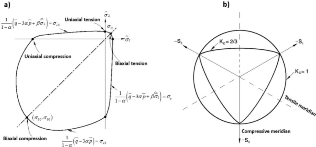
ˆmax 0), the yield surface function of Eq.1 reduces to Drucker-Prager yield condition in which the only parameter needed to define the yield surface is . The parameter then can be obtained by comparing the initial equibiaxial and uniaxial compressive yield stresses
b0and
c0according to Eq.3:
0 0 0 0 1 2 1 b c b c
(3)Typical values of the ratio
b0
c0
for concrete based on experimental results are reported in the range from 1.10 to 1.16, yielding values of between 0.08 and 0.12 (Lubliner et al (1989)). Finally, the parameter
determines the shape of the yield surface in the plasticity model and en-ters the yield function only for stress states of triaxial compression, when 0. The
coeffi-cient can be determined by comparing the yield conditions along the tensile and compressive merid-ians. This coefficient is obtained according to Eq.4:
3 1
2
1
c cK
K
(4)The coefficient Kc is the ratio of the hydrostatic effective stress in tensile meridian to that on
Figure 1: The yield surface in: a) plane stress cross section; b) deviatory plane (Lubliner et al (1989)).
The flow rule in concrete damage plasticity is introduced to the model as an essential element of plasticity theory utilizing non-associated flow potential functionG
. The CDP model usesDruck-er-Prager hyperbolic function as non-associated flow potential function according to Eq.5.
2 20
tan
tan
t
G
q
p
(5)The equation involves three material parameters. The first one is dilation angle
which is a concrete performance characterizing parameter when it is subjected to triaxial compound stress state. The next parameter ∈ is eccentricity which adjusts the shape of hyperbola in the plastic po-tential flow function. The eccentricity parameter is a small positive value and can be estimated as the ratio of concrete tensile strength to its compressive strength. The default value of eccentricity parameter is considered to be equal to 0.1. Finally, the last parameter of plastic flow potential func-tion is the concrete initial uniaxial tensile strength
t0.Damage in CDP model is associated with the failure mechanisms consist of concrete cracking and crushing, therefore the occurrence of damage leads to reduction in elastic stiffness. To introduce damage to the model Eq.6 is applied.
1
1
0:
pl
d d E
(6)Where
E is the initial (undamaged) elastic stiffness of the material and the operator (
0:
) denotes the product of the related tensors. Based on the scalar-damage theory, the stiffness degradation is isotropic and defined by a degradation variable d. Damage is defined in both tensile andcompres-sive states
d
tandd
cas functions of plastic strains. Damage parameter can take values in the range from zero (corresponding to undamaged material) to one (corresponding to fully damaged material).and consequently the stiffness degradation variable were modified. Visco-plastic strain rate tensor ( pl
) is defined according to Eq.7:
1 μ
pl pl pl
(7)Here p lis the evaluated plastic strain and the visco-plastic stiffness degradation variable d
is
defined according to Eq.8:
1 μ
d dd (8)
Where
d
is the evaluated degradation variable. The stress-strain relation based on viscoplastic model is defined according to Eq.9:
1
0:
pl
d E
(9)2.4 Material Model
2.4.1 Concrete Material Modeling
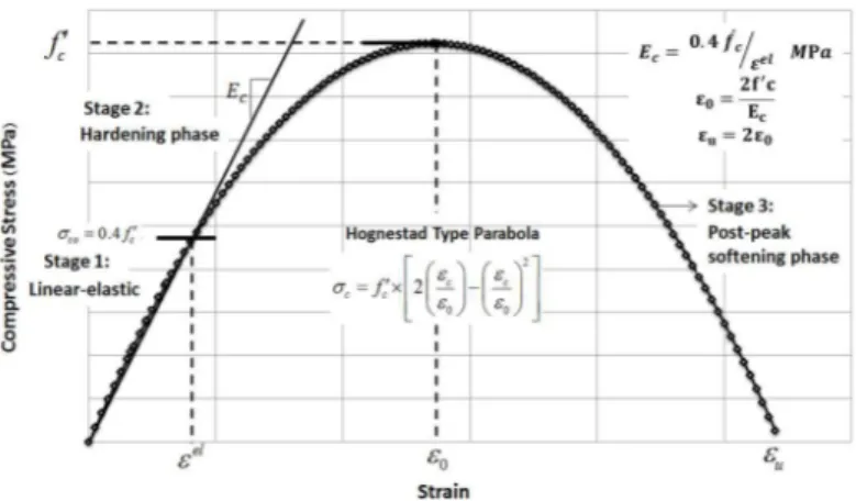
Uniaxial stress-strain behavior of concrete is simulated utilizing Hognestad type parabola (Hognes-tad (1951)). The uniaxial stress-strain behavior of concrete can be categorized into three main do-mains. The first one represents the linear-elastic branch which continues to reach the stress level of
co
that is taken as
co
0.4
f
c
. The second stage shows the hardening part of the concrete uni-axial compressive stress-strain behavior which describes the ascending branch of the stress–strain relationship reaching to the peak load at the corresponding strain level
0
2
f
c
E
c . The last part of concrete uniaxial compressive stress-strain relationship attributes to the post-peak softening be-havior and therefore represents the initiation and progression of compressive damage in the concrete material until the ultimate compressive strain
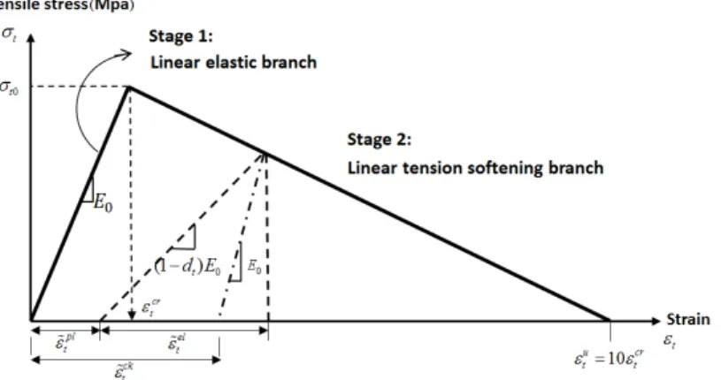
u. Figure 2 shows the compressive stress-strain be-havior of concrete which is introduced to the presented numerical model.The uniaxial stress-strain behavior of concrete in tension consists of two parts. As shown in Figure 3, the first part is a linear elastic behavior up to concrete tensile strength
t0. The secondphase initiates together with crack occurrence and its propagation in concrete material under ten-sion demonstrating a descending branch in the uniaxial tensile stress-strain diagram. The behavior in this phase is modeled by a softening procedure which can be modeled using linear, bilinear or nonlinear stress-strain relationships (Belarbi and Thomas (1994)). According to analysis assump-tions in this study the linear behavior is applied to the model. Figure 3 demonstrates details of ten-sile softening assumptions in the presented model.
Figure 3: Concrete uniaxial tensile stress-strain behavior and its softening branch assumptions.
The ultimate tensile strength of concrete is estimated by Eq.10 (Genikomsou and Polak (2015) and Wang and Vecchio (2006)).
0.33 (MPa)
t c
f f (10)
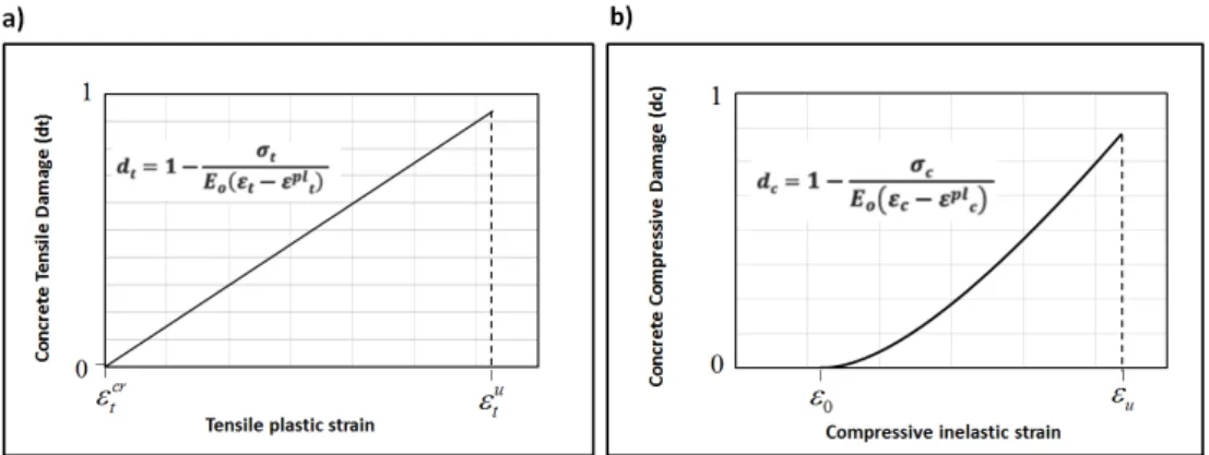
Damage is defined both for uniaxial tension and compression during softening procedure in con-crete damage plasticity model. Damage in compression occurs just after reaching to the maximum uniaxial compressive strength corresponding to strain level
0. The degradation of elastic stiffness in softening regime is characterized by two damage variables, dt and dc corresponding to tensile andcompressive damage, respectively, which are assumed to be functions of the plastic strains. Tensile and compressive damage in concrete damage plasticity model in the presented numerical model is assumed to be according to equations and diagrams of Figure 4.
2.4.2 Steel Reinforcement Modeling
Figure 4: Definition of damage parameter in CDP model: a) Uniaxial tensile damage; b) Uniaxial compressive damage.
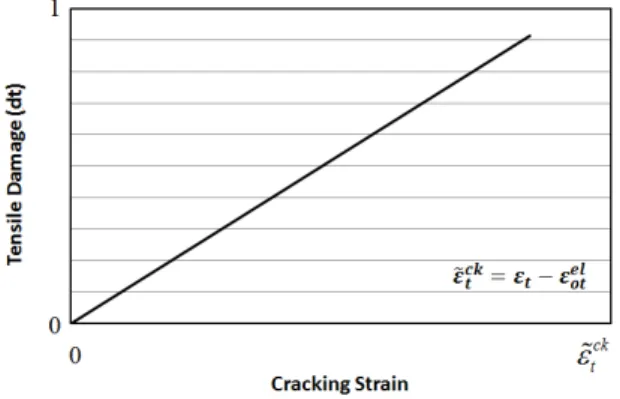
Most finite element studies of RC structures do not consider bond-slip of reinforcing steel and the inherent interaction between reinforcement and concrete in RC members. The post-failure be-havior for direct straining is modeled with tension stiffening in CDP model, which helps to define the strain-softening behavior for cracked concrete, therefore in order to consider concrete-reinforcement interaction such as bond slip, an indirect approach which defines "tension stiffening" into the reinforced concrete finite element model is applied as mentioned before in this study. Two different approaches to introduce tension stiffening to the numerical model are the application of post-failure stress-strain relation and the definition and application of fracture energy cracking crite-rion. The presented numerical model utilizes the first method (post-failure stress-strain relation) to appropriately introduce the tension stiffening behavior of reinforced concrete, the method in which post-failure properties of reinforced concrete is defined by giving the post-failure stress as a function of cracking strain ( ck
t
). Cracking strain is defined as the total strain minus the elastic strain corre-sponding to the undamaged material according to Eq.11 (Lubliner et al. (1989))
ck elt t ot
(11)The elastic strain of undamaged material ( el o t
) is defined according to Eq.12:0
el
ot t
E
(12)Figure 5: Tension stiffening data introduced to the numerical model in terms of tensile damage-cracking strain linear relationship.
3 VERIFICATION OF THE FINITE ELEMENT MODELING
An exterior half-scale beam-column connection namely test#2 conducted by Clyde et al (2000) and a full scale interior beam-column connection namely unit-01 tested by Hakuto et al (2000) are cho-sen to validate the numerical model. Both specimens were designed to have joint shear failure as their governing failure mode. To enforce shear failure in the joint, the beam longitudinal reinforce-ment of exterior beam-column connection was increased to prevent yielding and early degradation of the beam. To represent non-ductile detail of the joint, no transverse reinforcement was consid-ered within the joint panel in both cases (exterior and interior beam-column connections). It is worth mentioning that the interior beam-column connection tested by Hakuto et al (2000) is identi-cal to an interior beam- column connection of an existing RC building constructed in New Zealand before mid-1960s.
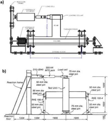
3.1 Boundary Conditions, Loading, Dimensions and Details
beam-column connection in one step only (lateral load). Cyclic horizontal loading was applied to the top end of the columns of the interior test unit using a double acting hydraulic jack.
Figure 6: Specimen dimensions and details: a) Exterior beam-column connection (Clyde et al (2000)); b) Interior beam-column connection (Hakuto et al (2000)).
3.2 Material Properties of the Test Specimens
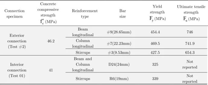
The measured uniaxial concrete compressive strength of the test specimens, the yield strength and the ultimate tensile strength of reinforcement used in the tests, are reported in Table 1.
Connection specimen Concrete compressive strength c
f
(MPa)Reinforcement type Bar size Yield strength y
F
(MPa) Ultimate tensile strength uF
(MPa) Exterior connection (Test #2) 46.2 Beamlongitudinal #9(28.65mm) 454.4 746
Column
longitudinal #7(22.23mm) 469.5 741.9
Stirrups #3(9.53mm) 427.5 654.3
Interior connection (Test 01) 41 Beam and Column longitudinal
D24(24mm) 325 Not
reported
Stirrups R6(19mm) 339 Not
reported
Table 1: Material properties of the test specimens.
4 FINITE ELEMENT ANALYSIS
4.1 Elements
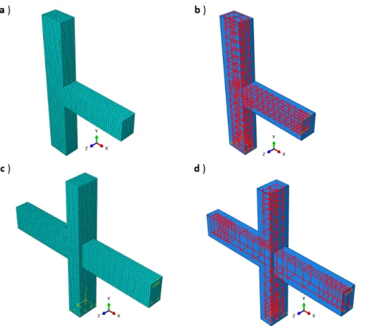
A uniform mesh size of 40 mm is chosen for the concrete elements over the whole geometry in both exterior and interior connection specimens as shown in Figure 8. The same size for reinforcement mesh is also adopted for steel bars. With this configuration, the exterior RC connection specimen has 11144 elements and 13414 nodes and the interior connection has 17414 elements and 21088 nodes. Details regarding element types are presented in Table 2.
Connection specimen Element type Element shape Geometrical order Number of
elements Exterior
connection (Test#2)
C3D8R Hexahedral Linear 9536
T3D2 Line Linear 1608
Interior connection
(Test 01)
C3D8R Hexahedral Linear 15328
T3D2 Line Linear 2086
Figure 8: Modeled specimens; a) Concrete element mesh of exterior connection; b) Reinforcement details of exterior connection; c) Concrete element mesh of interior connection and d) Reinforcement details of interior connection.
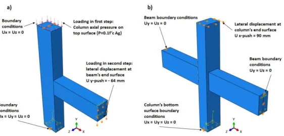
4.2 Model Geometry and Boundary Conditions
Restraints were defined at both top and bottom surfaces of the specimen's column in the exterior test specimen according to boundary conditions addressed in the test setup. Restraints are also de-fined in the interior connection specimen according to the test setup boundary conditions both on beam and column tip surfaces. Details regarding to the geometry and boundary conditions of the RC exterior and interior beam-column connections which are applied to the finite element models are illustrated in Figure 9.
Loading is introduced to the model in two separate steps in exterior beam-column connection. The column compressive axial load is applied to the column top surface in the first step which re-mained constant during the analysis procedure.
Figure 9: Simulated boundary conditions and loading of the specimens: a) Exterior beam-column connection; b) Interior beam-column connection.
4.2 Material Parameters and Calibration of the Model
The numerical model is calibrated on the experimental test results of exterior connection specimen as a reference experiment. The calibrated numerical model is then utilized to conduct nonlinear finite element analysis on the interior connection specimen (Test01).
Concrete material parameters used in the presented analysis consists of concrete Young’s modu-lus of elasticity (E0), Poisson’s ratio (ν) and concrete compressive and tensile strengths. The
poi-son’s ratio value for concrete material is considered to be equal to 0.2. The concrete damage plastic-ity input parameters which were discussed in section 2.3 are considered in the plasticplastic-ity model as presented in Table.3.
Plasticity Parameters Notation Parameter’s Value
considered in the model
Dilation angle 35° (calibrated)
Shape factor 0.667 (default value)
Stress ratio 1.16 (default value)
Eccentricity 0.1 (default value)
Table 3: Concrete damage plasticity input parameters.
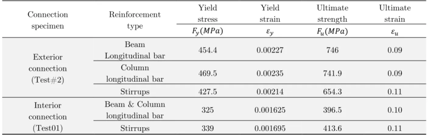
Figure 10: Typical uniaxial stress-strain behavior of reinforcements introduced to the numerical model.
Connection specimen
Reinforcement type
Yield stress
Yield strain
Ultimate strength
Ultimate strain
Exterior connection
(Test#2)
Beam
Longitudinal bar 454.4 0.00227 746 0.09
Column
longitudinal bar 469.5 0.00235 741.9 0.09
Stirrups 427.5 0.00214 654.3 0.11
Interior connection
(Test01)
Beam & Column
longitudinal bar 325 0.001625 396.5 0.10
Stirrups 339 0.001695 413.6 0.11
Table 4: Typical stress-strain properties of steel reinforcements.
In order to investigate the role of parameters in constitutive equations of damage plasticity model and to calibrate the model, effects of different logical values of the dilation angle and the viscosity parameter and mesh sensitivity analysis of the model are presented.
The dilatancy of concrete material represents the occurrence of volume expansion when the ma-terial is subjected to triaxial stress state and the consequent inelastic strain. Internal actions on the connection joint specimens under simulated lateral loads induce high shear stress in the joint core, an example of which compound stress state leads to considerable dilatancy sensitiveness of the ana-lytical model. A sensitivity analysis on dilation angle as a concrete material parameter is performed to investigate the parameter influence on lateral load-displacement response of the reference speci-men. Figure 11 shows that by increasing the value of dilation angle, the displacement capacity and the ultimate failure load of the connection are increased subsequently.
Figure 11: Lateral load-displacement response of FEA for different values of dilation angle.
The influence of visco-plastic regularization on the CDP constitutive equations through the in-troduction of viscosity parameter was another source of calibration process of the finite element analysis in this study. Defining visco-plastic regularization to the numerical model was first pro-posed as a method to improve the rate-dependent plastic damage model that brings uniqueness to the incremental stress field in the constitutive equations. It was shown that while the appropriate choice of viscosity parameter and defining it to the model provides relaxation time for visco-plastic system of equations to overcome convergence difficulties in the softening regime, the influence of considering different values of viscosity parameter in monotonic loading cases do not impose consid-erable amount of changes in the behavior of concrete material under uniaxial tension and compres-sion (Lee (1996)). It was shown that best results are obtained by small values of viscosity parameter compared to the pseudo time of analysis in the study performed by Lee (1996). Series of guidelines and recommendations are suggested by various researchers in order to consider best values of vis-cosity parameter in the CDP model depending on the type of predominant internal actions which are active and the degree of nonlinearity that involved in different problems (Wosatko et al (2015), Genikomsou and Polak (2015), Wei Ren et al (2015)).
The influence of considering additional relaxation time for the visco-plastic system on the analy-sis results using different values of viscosity parameter is shown in Figure 12.
According to the diagram of figure 12, the differences in the responses appear only at the soften-ing and to some extent at the hardensoften-ing regions. For constant element mesh size, when the viscosi-ty parameter was taken as a relative small value of 0.007985, the calculation procedure of the nu-merical results gave us the most accurate response in comparison to the experimental results. Also the concrete cracking pattern and the nature of joint shear failure were consistent with the test results.
Figure 12: Lateral load-displacement response of FEA for different values of the viscosity parameter.
Slight mesh size dependency is available in most distributed plasticity models which consider strain softening phenomenon in the constitutive equations (Genikomsou and Polak (2015)). It should be investigated that the mesh size dependency does not considerably affect the overall re-sponse of the specimen in FEA. It is notable that best results are obtained when the coarse mesh (40 mm) is used which may be due to the fact that most damage processes, causing concrete crack-ing propagation usually involve length scales in the order of two to three dominant aggregate sizes of the base concrete material (Bazant (1986)).
Figure 13: Lateral load-displacement response of RC exterior beam-column connection for 40mm and 25mm mesh sizes.
mod-el. The second approach is used in this study but the model is still slightly mesh size dependent however the influence of mesh size dependency on pushover lateral load-displacement behavior of the studied beam-column connections is within the acceptance limits for numerical simulations.
5 FINITE ELEMENT ANALYSIS RESULTS
The FEA results of the RC beam-column connections subjected to lateral loading is presented in terms of force-displacement curves, ultimate loads and displacements and cracking pattern which are monitored at different key points of shear behavior of the connection joints. Comparison be-tween force-displacement curves predicted by simulation and experimental results of exterior and interior connection specimens are presented in Figure 14 and Figure 15, respectively. Figure 14a, and Figure 15a, show the finite element analysis results of force-displacement curves which are compared with the envelope curve of the cyclic loading response shown in Figure 14b and Figure 15b which are obtained by experimental works of Clyde et al(2000) and Hakuto et al(2000) for ex-terior and inex-terior connection test specimens respectively.
Figure 14: Lateral load-displacement diagrams of exterior Test#2 specimen: a) Comparison between FEA and test; b) Test results of exterior specimen (Test#2) obtained by Clyde et al(2000) experimental study.
Peak lateral loads and displacements predicted by the numerical simulation and reported by experimental test results are presented in Table 5.
Connection specimen
Experimental results Finite element analysis results
Peak lateral load (kN)
Displacement at peak lateral load (mm)
Peak lateral load (kN)
Displacement at peak lateral load (mm) Exterior connection
(Test#2) 267 23.77 268.82 24.5
Interior connection
(Test 01) 89 60.5 87.38 58.97
Table 5: Ultimate lateral loads and displacements obtained from FEA and experiments.
The finite element analysis shows that the initial response is slightly stiffer than the test results. This may be due to effects of some assumed variables such as the choice of concrete tensile and compressive properties, or the uncertainties often involved with experimental efforts such as proba-ble existence of material deficiencies and also the inherent differences which exist between response obtained by cyclic loading of the experiment and monotonic loading in presented analysis may also contribute in limited stiffer initial response of FEA comparing to testing.
As shown in Figure 14 and Figure 15, three key points of shear behavior that are specified on the FEA resultant lateral load-displacement diagrams for both exterior and interior connection specimens, reasonably match with reported experimental results by Clyde et al (2000) and Hakuto et al (2000), respectively. Point A displays measurable beam flexural and joint shear cracking in exterior specimen and first diagonal shear cracking of the joint core in the interior specimen. Point B displays the ultimate strength of both exterior and interior specimens and finally point C is relat-ed to the end of FEA procrelat-edure attributrelat-ed to 25% drop of ultimate strength in exterior connection specimen test and 30% drop of ultimate strength in the interior connection specimen test.
Figure 16: FEA outputs of the exterior beam-column connection specimen at key points of shear behavior: a) Point A; b) Point B; c) Point C.
Exterior beam-column connection specimen experienced beam tensile damage at point A as shown in Figure 16a. The concrete tensile damage extended to the vicinity of the joint and the beam longitudinal bars were placed under tension. No yielding of longitudinal beam bars and also no compressive damage in the joint core were observed at this stage. Measurable flexural cracks in the beam and limited shear cracks in the joint were the main source of slight stiffness change at point A which confirms reported experimental observations at this stage. Limited shear cracking of the joint rapidly spread to the whole joint at point B as shown in Figure 16b. Concrete tensile damage is developed to the joint region followed by yielding of the beam longitudinal reinforcement. The post peak behavior of the connection specimen begins at this point due to compressive damag-ing of the concrete diagonal strut.
pattern observed in the test. The diagonal cracks in the joint region are propagated to vicinity of the column.
Figure 17: FEA outputs of the interior beam-column connection specimen at key points of shear behavior: a) Point A; b) Point B; c) Point C.
rein-forcement in the joint panel zone. The post peak behavior of the connection specimen also begins at this point due to the initiation of compressive damage in the concrete diagonal compressive strut.
Finally at the end of FEA procedure of the interior specimen (point C) corresponding to 30% drop in its ultimate strength, the failure of the connection specimen was occurred by crushing of the concrete diagonal strut in the joint region. As shown in Figure 17c the ultimate failure of the interi-or beam-column specimen is attributed to the joint shear failure as happened in the experiments. The numerical model shows good agreement between cracking pattern in the joint region obtained by FEA and the cracking propagation pattern observed in the test. Figure 18 presents a comparison between the cracking patterns of the joint region at ultimate strength (point B) for both exterior and interior specimens obtained by the FEA output and observed in the test results.
Figure 18: Comparison between joint shear cracking pattern obtained by the FEA output and observed in the test results at point B in: a) Exterior connection specimen; b) Interior connection specimen.
6 CONCLUSIONS
chosen as target model for this research. There was no transverse reinforcement considered in the joint panel zone.
The configuration of numerical model is implemented in finite element code ABAQUS. The fi-nite element model is validated with experimental results. Numerical results presented in terms of joint shear capacity, deformations and cracking pattern at introduced key points of joint shear be-havior conform appropriately to experimental results. The finite element analysis results confirms the capability of the developed finite element model in this study to predict RC beam-column joint shear behavior and can be further investigated and validated for different types of joints. The model can be used as an efficient and powerful numerical tool for further studies on different RC beam-column joints.
References
ABAQUS Analysis user’s manual 6.14-EF (2014). Dassault Systems Simulia Corp. Providence, RI, USA.
ACI 318-14. (2014). Building Code Requirements for Structural Concrete, Reported by American Concrete Institute Committee 318.
ACI 352R-02. (2002). Recommendations for Design of Beam-Column Connections in Monolithic Reinforced Concrete Structures, Reported by Joint ACI-ASCE Committee 352.
ASCE41-13. (2013). Seismic Evaluation and Retrofit of Existing Buildings: American Society of Civil Engineers, Reston, Virginia.
Bazant, Z.P. (1986). Mechanics of distributed cracking, ASME, Applied Mechanics 39(5): P. 227.
Belarbi, A., Thomas, T.C. (1994) Constitutive laws of concrete in tension and reinforcing bars stiffened by concrete. ACI Structural Journal 91(4): 465-474.
Campione, G., Cavaleri, L., Papia, M. (2015). Flexural response of external R.C. beam–column joints externally strengthened with steel cages, Engineering Structures 104: 51–64.
Clyde, C., Pantelides, C.P., Reaveley R.D. (2000). Performance based evaluation of exterior reinforced concrete building joints for seismic excitation. PEER Report 2000/05 Pacific Earthquake Research Center, College of Engi-neering University of California, Berkeley
Elsouri, A.M., Harajli, M.H. (2013). Seismic response of exterior RC wide beam–narrow column joints: Earthquake-resistant versus as-built joints, Engineering Structures 57: 394-405.
Eslami, A., Ronagh, H. R. (2014) Experimental investigation of an appropriate anchorage system for flange-bonded carbon fiber–reinforced polymers in retrofitted RC beam–column Joints, ASCE J. Composites for Construction 18(4): 04013056.
Esmaeeli E., Barros, J.A.O., Sena-Cruz, J., Fasan, L., Prizzi, F.R.L., Melo, J., Varum, H. (2014). Retrofitting of interior RC beam-column joints using CFRP strengthened SHCC: cast-in-place solution, Composite Structures doi: 10.1016/j.compstruct.2014.12.012.
Esmaeeli, E., Barros, J.A.O., Sena-Cruz, J., Varum, H., Melo, J. (2015). Assessment of the efficiency of prefabricated hybrid composite plates (HCPs) for retrofitting of damaged interior RC beam–column joints, Composite Structures 119: 24–37.
Favvata, M.J., Izzuddin, B.A., Karayannis, C.G. (2008). Modelling exterior beam–column joints for seismic analysis of RC frame structures, Earthquake Engineering and Structural Dynamics 37: 1527–1548.
Genikomsou, A.S., Polak, M.A. (2015). Finite element analysis of punching shear of concrete slabs using damaged plasticity model in ABAQUS, Engineering Structures 98: 38–48.
Haach, V.G., El Debs, A., El Debs, M. (2008). Evaluation of the influence of the column axial load on the behavior of monotonically loaded RC exterior beam– column joints through numerical simulations. Engineering Structures 30(4): 965–975.
Hakuto, S., Park, R., Tanaka, H. (2000). Seismic load tests on interior and exterior beam- column joints with sub-standard reinforcing details. ACI structural J. 97(1): 11-25.
Hanson, N.W., Connor, H.W. (1967). Seismic resistance of reinforced concrete beam–column joints. J. Structural Division ASCE 93(5): 533–59.
Hognestad, E. (1951). A study of combined bending and axial load in reinforced concrete members, University of Illinois, engineering experiment station, bulletin series No.399.
Jong-Su Jeon, Shafieezadeh, A., DesRoches, R. (2014). Statistical models for shear strength of RC beam-column joints using machine-learning techniques, Earthquake Engineering and Structural Dynamics. 43: 2075–2095.
Jung-Yoon Lee, Jin-Young Kim, Gi-Jong Oh (2009). Strength deterioration of reinforced concrete beam_column joints subjected to cyclic loading, Engineering Structures 31: 2070_2085.
Kim, J., LaFave, J.M. (2007). Key influence parameters for the joint shear behaviour of reinforced concrete (RC) beam–column connections, Engineering Structures 29: 2523–2539.
Kotsovou G., Mouzakis, H. (2012). Seismic design of RC external beam-column joints. Springer, Bulletin of Earth-quake Engineering 10: 645–677.
Kotsovou, G., Mouzakis, H. (2012). Exterior RC beam–column joints: new design approach, Engineering Structures 41: 307–319.
Lee, J., (1996). Theory and implementation of plastic-damage model for concrete structures under Cyclic and Dy-namic Loading, Ph.D. Thesis (in English), University of California, Berkeley, USA.
Lee, J., Fenves, G.L. (1998). Plastic-Damage Model for cyclic loading of concrete structures. Journal of Engineering Mechanics. 124(8) (1998) 892-900.
Lima, C., Martinelli, E., Faella, C. (2012). Capacity models for shear strength of exterior joints in RC frames: exper-imental assessment and recalibration, Springer Bulletin of Earthquake Engineering 10: 985–1007.
Lubliner, J., Oliver, J., Oller, S., Oñate, E. (1989). A plastic-damage model for concrete, International Journal of Solids and Structures 25: 299-329.
Mahini, S.S., Ronagh, H.R. (2011). Web-bonded FRPs for relocation of plastic hinges away from the column face in exterior RC joints, Composite Structures 93(10) (2011) 2460–72.
Maria Teresa De Risi, Paolo Ricci, Gerardo Verderame, M., Gaetano Manfredi. (2016). Experimental assessment of unreinforced exterior beam–column joints with deformed bars, Engineering Structures 112: 215–232.
Masi, A., Santarsiero, G., Lignola, G.P., Verderame, G.M. (2013). Study of the seismic behavior of external RC beam–column joints through experimental tests and numerical simulations, Engineering Structures 52: 207–219. Mostofinejad, D., Talaeitaba, S.B. (2006). Finite element modeling of RC connections straightened with FRP lami-nates. Iranian J Science and Technology, Trans B, Eng. 30(B1):21–30.
Muhsen, B.A., Umemura, H. (2011). New Model for Estimation of Shear Strength of Reinforced Concrete Interior Beam-Column Joints, Procedia Engineering 14: 2151–2159.
NEHRP (1997). Guidelines for the seismic rehabilitation of buildings. Federal Emergency Management Agency, FEMA 273
Niroomandi, A., Maheri, A., Maheri, M.R., Mahini, S.S. (2010). Seismic performance of ordinary RC frames retrofit-ted at joints by FRP sheets, Engineering Structures 32: 2326–2336.
Niroomandi, A., Najafgholipour, M.A., Ronagh, H.R. (2014). Numerical investigation of the affecting parameters on the shear failure of Non-ductile RC exterior joints, Engineering Failure Analysis 46: 62-75.
Pantelides, C.P., Hansen, J., Nadauld, J., Reaveley R.D. (2000). Assessment of reinforced concrete building exterior joints with substandard details. PEER Report 2000/05 Pacific Earthquake Research Center, College of Engineering University of California, Berkeley
Park, S., Mosalam, K.M. (2012). Experimental and analytical studies on reinforced concrete buildings with seismical-ly vulnerable beam- column joints. PEER Report 2012/03 Pacific Earthquake Research Center, Department of Civil and Environmental Engineering University of California, Berkeley
Park, S., Mosalam, K.M. (2012). Parameters for shear strength prediction of exterior beam–column joints without transverse reinforcement, Engineering Structures 36: 198–209.
Parvin, A., Granata, P. (2000). Investigation on the effects of fiber composites at concrete joints, Composites Part B Engineering 31(6): 499-509.
Paulay, T., Park, R., Priestley, M.J.N. (1978). Reinforced concrete beam–column joints under seismic actions. ACI J, 75(11): 585–93.
Pauletta, M., Di Luca, D., Russo, G. (2015). Exterior beam column joints shear strength model and design formula, Engineering Structures 94: 70–81.
Saptarshi Sasmal, Ramanjaneyulu, K., Balthasar Novák, Lakshmanan, N. (2013). Analytical and experimental inves-tigations on seismic performance of exterior beam–column subassemblages of existing RC-framed building, Earth-quake Engineering and Structural Dynamics 42: 1785–1805.
Sharma, A., Eligehausen, R., Reddy, G.R. (2011). A new model to simulate joint shear behavior of poorly detailed beam–column connections in RC structures under seismic loads, Part I: Exterior joints, Engineering Structures 33: 1034–1051.
Shayanfar, J., Akbarzadeh Bengar, H., Niroomandi, A. (2016). A proposed model for predicting nonlinear behaviour of RC joints under seismic loads, Materials and Design. 95: 563–579.
Shwan, H.S., Abdul Razak, H. (2016). Structural behavior of RC engineered cementitious composite (ECC) exterior beam–column joints under reversed cyclic loading, Construction and Building Materials. 107: 226–234.
Vecchio, C.D., Ludovico, M.D., Prota, A., Manfredi, G. (2016). Modelling beam-column joints and FRP strengthen-ing in the seismic performance assessment of RC existstrengthen-ing frames, Composite Structures, doi: http://dx.doi.org/10.1016/j.compstruct.2016.01.077.
Voyiadjis, G.Z., Taqieddin, Z.N. (2009), Elastic plastic and damage model for concrete materials: Part I – Theoreti-cal formulation. Int J Struct Changes Solids – Mech Appl,1(1):31–59.
Wael Kassem. (2016). Strut-and-tie modelling for the analysis and design of RC beam-column joints, Materials and Structures 49(8): 3459–3476.
Wang, P.S., Vecchio, FJ. (2006). VecTor2 and formworks user manual, University of Toronto, Canada.
Wei Ren, Sneed, L.H., Yang Y., Ruili, H. (2015). Numerical simulation of pre-stressed precast concrete bridge deck panels using damage plasticity model, Int J Concrete Struct and Materials, 9(1):45-54
Wong, H.F., Kuang, J.S. (2014). Predicting shear strength of RC interior beam–column joints by modified rotating-angle softened-truss model, Computers and Structures 133: 12–17.
Wosatko, A., Pamin, J., Polak M.A. (2015). Application of damage-plasticity models in finite element analysis of punching shear, Computers and structures 151: 73–85.