Joana Cristina Almeida Andrade Dias da Costa
Development of high specific strength
components, with internal cellular structure,
for several applications
Joana Cristina Almeida Andrade Dias da Costa
De
velopment of high specific s
tr engt h com ponents, wit h inter nal cellular s tr uctur e, for se ver al applications
Universidade do Minho
Escola de Engenharia
Dissertação de Mestrado
Mestrado em Engenharia Mecânica
Trabalho efectuado sob a orientação do
Professor Doutor Filipe Samuel Correia Pereira Silva
Joana Cristina Almeida Andrade Dias da Costa
Development of high specific strength
components, with internal cellular structure,
for several applications
Universidade do Minho
A
CKNOWLEDGMENTS
This work has been possible thanks to the collaboration of many people within the Department of Mechanical Engineering of the University of Minho.
Inside the Department of Mechanical Engineering, special gratitude is given to Professor Filipe Samuel Silva and Jorge Martins for their support and orientation during this work.
I also would like to thank Engineer Paulo Pinto for his help with the cellular structure drawings. I would like to thank João Faria, Nélson Lima and Joel Silva, for the help with the 3D printer machine.
I also have to thank to my family, my mother, my father and my grandmother, without them it would be impossible to finish this work. And to my sister and brother, for putting up with me. I would like to address a special gratitude to my friends, Flávia Barbosa, who helped me with the Word and the Excel, José Grilo and Filipe Pimenta, who gave me support on SolidWorks and finally Ana Carvas, Pedro Silva , Daniel Aires and Beatriz Matos for their friendship.
A
BSTRACT
Today's society is characterized as a consumer society in terms of natural resources. In this sense, the most important resources are related to energy and materials. The goal is to try to reduce this excessive consumption of resources. One of the solutions is to turn the use of the raw material more efficient in components, in this case applied to mechanical engineering. The subject of this dissertation, "Development of high specific strength components, with internal
cellular structure, for several applications", meets the goal of the material used, thus aiming to
reduce the amount of material in areas where it is not being properly employed.
The first step was to choose an iconic component of mechanical engineering, a heavy duty piston. From the original design of that piston is made a static simulation, where the boundary conditions are the result of state of the art. With the results of that simulation it is possible to extract and analyze the areas where stresses are not too high, comparing to the maximum stress. These are areas that are likely to be improved iteratively making the piston lighter than the original. Moreover, a thermal analysis was performed, since the piston is subject to high thermal loads. At the end, the simulations of either the conventional piston or the idealized piston, are compared and the mechanical and thermal properties are kept.
After the computational validation of the new component, proceed to the 3D printing in PLA.
R
ESUMO
A sociedade de hoje é caracterizada como sendo uma sociedade consumista em termos de recursos naturais. Neste sentido, os recursos mais importantes estão ligados à energia e aos materiais. A questão é de tentar reduzir este consumo excessivo de recursos. Umas das soluções é praticar um uso eficiente do material em componentes, neste caso, aplicados à engenharia mecânica. O tema desta dissertação, “Desenvolvimento de peças de elevada resistência
específica, com estrutura celular, para aplicações diversas”, vai de encontro ao
aproveitamento do material usado, visando assim reduzir a quantidade de material em zonas em que o mesmo não está a ser propriamente aproveitado.
O primeiro passo foi escolher um componente icónico da engenharia mecânica, um pistão utilizado em transportes pesados. A partir do desenho original desse mesmo pistão é feita uma simulação estática, onde as condições de fronteira são fruto do estado da arte. Através dos resultados dessa mesma simulação é possível extrair zonas onde as tensões não são elevadas, comparando com a tensão máxima. São essas zonas que são passíveis de ser iterativamente melhoradas tornando o pistão mais leve do que o original. Também foi realizada uma análise térmica, dado que o pistão está sujeito a elevadas cargas térmicas. No final, as simulações, quer do pistão convencional quer do pistão idealizado, são comparadas e as propriedades mecânicas e térmicas são mantidas.
Após a validação computacional do novo componente, procede-se à impressão de ambos os pistões em PLA.
Palavras-chave: Estruturas Celulares, Propriedades Mecânicas, Pistão Para Transportes Pesados.
C
ONTENTS
Acknowledgments ... i Abstract ... iii Resumo ... v Contents ... vii List of figures ... xi List of Tables ... xvAbreviations and Symbols ... xvii
1. Introduction ... 1
1.1 Cellular structures ... 1
1.2 Scope and structure of the thesis ... 2
1.3 Motivation ... 3
1.4 Aims... 3
2. State of the art ... 5
2.1 Piston terminology ... 5
2.2 Piston as a component of power transmission ... 7
2.3 Mechanical loads ... 10
2.4 Thermal loads ... 10
2.5 Piston materials... 11
2.5.1 Aluminium ... 11
2.5.2 Ferrous materials ... 12
2.6 Methods of piston cooling ... 14
2.6.1 Pistons without piston cooling ... 15
2.6.2 Pistons with spray jet cooling... 15
2.6.3 Pistons with cooling channels ... 15
2.7 Processes of Manufacture ... 18
2.8 Piston Types ... 19
2.8.2 Surface treatment ... 23
2.8.3 Cooling gallery ... 24
viii
2.8.5 Combined pistons ... 26
2.8.6 Wear resistant inserts in the first piston groove ... 26
2.8.7 Steel pistons ... 27
3. Methodology ... 29
3.1 Design ... 30
3.2 Analysis of the slider-crank mechanism ... 31
3.3 Static analysis-conventional piston ... 36
3.3.1 Mesh ... 39
3.3.2 Maximum von Mises Stress Criterion ... 41
3.3.3 Stress results- Gas pressure ... 42
3.3.4 Static analysis results- Inertia ... 44
3.4 Thermal analysis ... 45
3.4.1 Boundary conditions ... 46
3.4.2 Thermal analysis results- Conventional piston ... 48
3.5 Optimisation ... 52
3.5.1 Main body ... 53
3.5.2 Crown ... 54
3.5.3 Piston boss ... 55
3.5.4 Skirt ... 57
3.6 Static analysis – optimised piston ... 58
3.7 Thermal analysis - optimised piston ... 61
3.8 Results comparison ... 65
4. Manufacture process ... 69
4.1 3D Printing ... 69
4.1.1 Machine setup ... 71
5. Conclusions and future work ... 77
5.1 Conclusions ... 77
5.1.1 Design ... 77
5.1.2 Static analysis ... 77
5.1.4 Thermal analysis ... 78
5.1.5 Manufacture process ... 78
5.2 Future work... 79
L
IST OF FIGURES
Figure 1.1 Relationship between: Processing, Theory, Characterization and Mechanical
Properties [1] ... 1
Figure 1.2 Honeycomb structure [2] ... 2
Figure 2.1 Piston terminology ... 5
Figure 2.2 Types of piston crowns (1-3 for four-stroke gasoline engines with multi-point injection, 4 for four-stroke gasoline engines with direct injection, 5-6 four-stroke diesel engines with direct injection) [5] ... 6
Figure 2.3 Bearing and bushings [6] ... 7
Figure 2.4 Skirt shapes [6] ... 7
Figure 2.5 Forces on the piston [6] ... 8
Figure 2.6 Force graphic [6] ... 8
Figure 2.7 Temperature profile of diesel and gasoline pistons [6] ... 11
Figure 2.8 Phase diagram AlSi [6] ... 12
Figure 2.9 Phase diagram FeC [6] ... 13
Figure 2.10 Representation of a Steel and an Al piston, on the left a Steel piston and on the right an Al piston [9] ... 14
Figure 2.11 Piston without cooling gallery [6] ... 15
Figure 2.12 Salt core cooling channel on the left, piston with cooled ring carrier on the right.[6] ... 16
Figure 2.13 Forged piston for Formula 1 [6] ... 19
Figure 2.14 Gasoline pistons [7] ... 21
Figure 2.15 Diesel pistons [7] ... 21
Figure 2.16 Thermal expansion control [13] ... 23
Figure 2.17 Wear resistant surface [8] ... 24
Figure 2.18 Cooling gallery [6] ... 25
Figure 2.19 Piston with cooled ring carrier [8] ... 25
Figure 2.20 Combined, or articulated piston [6] ... 26
Figure 2.21 Piston with wear resistant inserts in the first groove [8] ... 27
Figure 2.22 Steel pistons, by Mahle [6] ... 27
xii
Figure 3.2 Heavy duty piston ... 30
Figure 3.3 slider-crank mechanism [16] ... 32
Figure 3.4 Piston position graphic... 33
Figure 3.5 Linear velocity graphic ... 34
Figure 3.6 Linear acceleration graphic ... 35
Figure 3.7 Inertia graphic- conventional piston ... 36
Figure 3.8 Simulation steps ... 37
Figure 3.9 Static analysis process [18] ... 38
Figure 3.10 Constraint feature- conventional piston ... 39
Figure 3.11 Types of Solid mesh [20] ... 40
Figure 3.12 Mesh details ... 41
Figure 3.13 Static analysis- conventional piston ... 42
Figure 3.14 Maximum stress of the static analysis- conventional piston ... 43
Figure 3.15 Displacement results- conventional piston ... 43
Figure 3.16 Factor of safety- conventional piston... 44
Figure 3.17 Inertia- conventional piston ... 44
Figure 3.18 Scheme of the heat transfer between the cylinder and the piston wall ... 46
Figure 3.19 The coordinate system used for the notations for oil jet cooling [23] ... 47
Figure 3.20 Temperature distribution in the piston- conventional piston ... 49
Figure 3.21 Thermal results section- conventional piston ... 49
Figure 3.22 Sections views of the crown (1-0mm from the top, 2- 10 mm from the top, 3- 20mm from the top, 4-20 mm from the top-conventional piston) ... 50
Figure 3.23 Profile temperatures crown ... 51
Figure 3.24 Profile temperatures wall ... 51
Figure 3.25 Heat flux in the piston- conventional piston ... 52
Figure 3.26 Mass sensor ... 52
Figure 3.27 Wall thickness- optimised piston ... 53
Figure 3.28 Inner side curvature ... 54
Figure 3.29 Piston crown measurements and 3D model- optimised piston ... 54
Figure 3.30 Pin boss with a cellular structure ... 55
Figure 3.31 Cellular structure ... 56
Figure 3.32 Connection between the cellular structure and the wall ... 56
Figure 3.34 Section view of the skirt, on the right of the conventional piston and on the left of
the optimised piston ... 57
Figure 3.35 Static analysis results- optimised piston ... 58
Figure 3.36 Static analysis results, probe above 75 MPa- optimised piston ... 59
Figure 3.37 Factor of safety- optimised piston ... 59
Figure 3.38 Inertia graphic- optimised piston ... 60
Figure 3.39 Inertia- optimised piston ... 61
Figure 3.40 Thermal analysis results- optimised piston ... 62
Figure 3.41 Section view, plan XZ ... 62
Figure 3.42 Section view, plan XY ... 63
Figure 3.43 Section view 10 mm from the top- optimised piston ... 64
Figure 3.44 Heat flux- optimised piston ... 64
Figure 3.45 Maximum temperatures with different combustion temperatures ... 67
Figure 4.1 Manufacture process [25] ... 69
Figure 4.2 Plaster thermal cycle ... 70
Figure 4.3 Skirt changed due to machine restriction ... 70
Figure 4.4 Pin boss wall ... 71
Figure 4.5 Piston placement ... 72
Figure 4.6 Machine Setup ... 72
Figure 4.7 Inner side of the PLA model ... 73
Figure 4.8 Problems with the support ... 73
Figure 4.9 3D printer support ... 74
Figure 4.10 Piston chamber, PLA model ... 74
L
IST OF
T
ABLES
Table 2.1 Operating conditions and solutions approaches for piston design and material[6] . 17
Table 3.1 Main dimensions of the piston ... 31
Table 3.2 Volumetric properties ... 31
Table 3.3 Mechanical properties of the aluminium alloy 4032 T6 ... 37
Table 3.4 Contents of the aluminium alloy 4032 T6 ... 37
Table 3.5 oil properties ... 45
Table 3.6 Jet properties ... 45
Table 3.7 Piston information ... 46
Table 3.8 Values of a and b [23] ... 48
Table 3.9 Different values of h with fluctuations on the temperature ... 48
Table 3.10 Volumetric properties, optimised piston ... 57
Table 3.11 Results ... 65
A
BREVIATIONS AND
S
YMBOLS
Symbol Definition Unit
Abbreviations
Al Aluminium -
BDC Bottom dead centre -
CAD Computer aided design -
Cu Cupper -
Fe Iron -
FOS Factor of safety Dimensionless
Mg Magnesium Roman symbols 𝑎 Linear acceleration 𝑚/𝑠2 𝑎𝑝 Linear acceleration 𝑚/𝑠2 FK Piston force N FS Lateral force N FST Rod force N ℎ Convection coefficient W/m2K 𝑘 Thermal conductivity W/mK
𝑙 Length of the connecting rod 𝑚
𝑚 Total of mass kg
𝑚𝑟𝑜𝑑 Mass of the rod kg
𝑚𝑝𝑖𝑠𝑡𝑜𝑛 Mass of the pin kg 𝑛
Ratio between the length of the connecting rod the crank
radius
Dimensionless
N Angular velocity Revolutions per second
Nu Nussle Dimensionless Pr Prandtl Dimensionless Re Reynolds Dimensionless 𝑈 Oil velocity m/s 𝑇 Temperature in the combustion chamber ℃
xviii 𝑣𝑗𝑒𝑡 Jet’s velocity m/s 𝑣𝑝𝑖𝑠𝑡𝑜𝑛 Piston’s velocity m/s 𝑥 Piston’s position m Greek symbols 𝛼 Angular acceleration 𝑟𝑎𝑑/𝑠2 𝜃 Crankshaft degree 𝑟𝑎𝑑 𝜔 Angular velocity 𝑟𝑎𝑑/𝑠 𝜌 Density 𝑘𝑔/𝑚3
𝜎𝑙𝑖𝑚𝑖𝑡 Limit stress of the material MPa
𝜎𝑣𝑜𝑛𝑀𝑖𝑠𝑒𝑠 Maximum stress MPa
𝛾 Kinematic viscosity 𝑚2/𝑠
1. I
NTRODUCTION
This chapter is present a brief explanation on cellular structures as well as the connection between processing, theory, mechanical properties and characterization. It also guarantees the aims, the dissertation layout and the motivation.
1.1 Cellular structures
When modern man builds large load-bearing structures, he uses dense solids: steel, concrete, glass. When nature does the same, it generally uses cellular structures such as: wood, bone, coral. There must be good reasons for it.
The use of cellular structure allows the material to have good mechanical properties as well as low mass. Materials with cellular structure generally occur in nature and have many possible engineering applications. Examples of cellular structures in nature are wood, bone, cork, plant stems, glass sponges and bird beaks. Man has made many synthetic cellular structures, such as honeycomb-like materials used for lightweight aerospace components.
The successful application of materials requires that they satisfy a set of properties. These properties can be thermal, optical, mechanical, physical, chemical and nuclear. Those properties are linked to the structure of the materials and the way of its manufacturing process. A schematic framework that shows the relationship between the four elements: mechanical properties, characterization, processing and theory is present in Figure 1.1.[1]
2
Cellular structures (metal foams, “metfoams” or cellular metals) are a new class of material unfamiliar to mechanical engineers. They are made possible by a range of novel processing techniques, many of which are still under development.[2] At the present, University of Minho has a new technique that makes it possible to produce new lightweight components with cellular structures.
One of the potentialities of the cellular structures is its behavior to compression that, to impact requirements is an important factor. On using this kind of structure is possible to make lower components.[3]
One of the examples of cellular structures is the honeycomb structure. This type of structure is used in airplane, ship and automobile constructions. The design is achieved with two thin walls and the honeycomb structure between them, see Figure 1.2.
Figure 1.2 Honeycomb structure [2]
1.2 Scope and structure of the thesis
This dissertation is concerned with the development of an optimised piston based on a conventional piston and also a static analysis and a thermal analysis in order to compared them with each other and validate the final CAD model.
This work is elaborated in 5 chapters. Chapter 2 deals with the state of the art, in order to define the boundary conditions for the study. This chapter is designed to give the readers with different backgrounds to a common level of knowledge. The main covered topics are: the 1) Piston terminology, 2) Piston as a component of power transmission, 3) Mechanical loads, 4) Thermal loads, 5) Piston materials, 6) Methods of cooling, 7) Processes of manufacture, 8) Piston types.
The third chapter contains the methodology, is devoted to the piston mas optimisation with the main analysis, thermal and mechanical. It covers 8 sections: 1) Design (chosen piston), 2) Analysis of the slider-crank mechanism, 3) Static analysis – conventional piston, 4) Thermal analysis – conventional piston, 5) Optimisation, 6) Static analysis – optimised piston, 7) Thermal analysis – optimised piston and 8) results.
The fourth chapter, named as Manufacture process, mainly describes the 3D printing process. Finally, Chapter 5, encompasses a list of future work and the main conclusions are drawn.
1.3 Motivation
Having the possibility of applying an existent lightweight cellular structure to an iconic mechanical component, a piston, was a challenge.
Knowing that pistons are components with severe requirements, due to structural and thermal operating conditions, was the major motivation on this work. Studying how they have developed and understand how they work fulfilled many engineering fields, from computer aided design and simulations to the manufacture process.
The basic requirement for the successful fulfilment of the function of a structure is that the working stresses in critical sections, cannot exceed the allowed limit of the material. The request of lightweight design is to use maximal available material resources with the minimum mass. Therefore, having the opportunity of change a conventional piston and optimised it, reducing its mass, was a motivating challenge.
1.4 Aims
The purpose of this work is to design a heavy duty piston using some of the properties of cellular structures in order to reduce its mass in 30%. The specific aims of this work are:
Design a new heavy duty piston, applying a cellular structure, through an existent conventional piston;
Perform a static analysis on the conventional piston and from that data redesign an optimised piston;
Perform a thermal analysis on both pistons;
2. S
TATE OF THE ART
Engine piston is one of the most complex mechanical component among all automotive field. Piston materials and its design have been under development during the years and it will be that way until fuel cells, exotic batteries or another thing that can replace the conventional way of energy transformation on an engine. [4]
2.1 Piston terminology
Functional divisions of the piston are the crown, the ring belt with top land, the pin boss and, finally, the piston skirt, see Figure 2.1 . There are more elements on pistons, such as cooling galleries and ring carriers that specifies the type of piston design. [5]
Figure 2.1 Piston terminology
The upper part, or top, of the piston is named the crown, and it is exposed to the cylinder chamber and, therefore, the effects of the pressure and heat from the combustion.
6
The piston head or crown forms the cavity of the combustion chamber. For diesel and gasoline pistons, the combustion chamber comes in different geometries, due to the number and location of the valves, see Figure 2.2. [5]
Figure 2.2 Types of piston crowns (1-3 for four-stroke gasoline engines with multi-point injection, 4 for four-stroke gasoline engines with direct injection, 5-6 four-stroke diesel engines with direct injection) [5]
The piston ring belt is divided in three ring grooves that are made to hold the piston rings. There are two basic types of piston rings. The top two rings are the compression rings, which are designed to seal the expanding gases in the combustion chamber. The third ring is responsible to control the oil, it must scrape the oil down the cylinder walls and prevent it from entering the combustion chamber.
The pin bore, or pin boss, sliding mechanism must be in the highest condition in order to keep the engine in reliable conditions. If the surface roughness is too low this can cause galling of the pin bore. Some pistons use bearing and bushings, see Figure 2.3, its primary function is to support the moving parts while absorbing and transferring occurring forces. [6]
Figure 2.3 Bearing and bushings [6]
The piston skirt is the part of a piston that extends the lowest. It is tasked with keeping the piston from shocking excessively in the cylinder. It is typically machined with small grooves to help in holding and transporting oil to the cylinder walls to provide proper lubrication. In some high-performance applications, the piston skirt may be coated with a type of material which aids in lubrication and prevents scuffs from occurring on the cylinder wall. On Figure 2.4 is possible to see 3 different types of skirt’s shape. [6]
Figure 2.4 Skirt shapes [6]
2.2 Piston as a component of power transmission
In a cylinder engine, the energy bound up in the fuel is quickly transformed into heat and pressure during the combustion cycle. The heat and pressure values rise critically within a very short period of time. The piston, as a moving component of the combustion chamber, is in charge of converting this released energy into mechanical work.[6]
8
Figure 2.5 Forces on the piston [6]
The gas pressure pushed against the piston head and the oscillating inertial forces of the piston plus the connecting rod constitute the piston force (FK). Due to the redirection of the piston force in the direction of the rod (rod force FST), an additional component ascends – following the force parallelogram – known as the lateral force FS, or normal force. This specific force presses the piston skirt against the cylinder bore. Shown in Figure 2.5 and Figure 2.6. [6]
As a moving and force-transmitting part, the piston, with the piston rings, must conveniently seal the combustion chamber against gas passage and the penetration of oil under all load conditions. This task can only be fulfilled if a hydrodynamic lubricating is between the piston rings or skirt and the cylinder bore. The stoppage of the piston at the two dead centre points (top dead centre and bottom bead centre), where the oil is not correctly functional, is particularly critical.[6]
It is now presented the most important tasks that the piston must achieved, such as: Transmission of force from and to working gas;
Sealing off the working chamber;
Linear guiding of the connecting rod; ( trunk piston engines ) Heat dissipation;
Controlling charge exchange; ( in two strokes engines ) Guiding the sealing elements; ( piston rings )
Guiding the connecting rod. ( for top-guided connecting rods ) Pistons have to fulfil many different tasks such as:
Structural strength;
Adaptability to operating conditions; Low friction;
Heat dissipation; Low wear;
Seizure resistance and simultaneous running smoothness; Low weight with sufficient shape stability;
Low oil consumption ;
10
This requirements are, in part, contradictory, both in terms of design and material. These conditions must be carefully coordinated for each engine type. The optimal solution can therefore be quite different for each individual case. [6]
2.3 Mechanical loads
The cyclical loading of the piston is due to:
The gas pressure from de cylinder pressure;
The inertia force from the oscillating motion of the piston;
The lateral force from the support of the gas force by the inclined rod, and the inertia force of the oscillating connecting rod.
The simulation of the gas force is intended to represent the effect of the gas pressure on the piston ate the top dead centre position. The gas pressure is applied to the CAD model over the entire piston crown.
The oscillating motion of the piston in the cylinder generates accelerations that reach the maximum at the top dead centre. In this context, the length of the rod relative to the crank radius pin, also known as the stroke-connecting rod ratio, plays a big role. As the length of the rod increases, the acceleration of the piston and the lateral forces decrease. Maximising the length of the connecting rod becomes by means one design principle. The accelerations are linearly dependent on the stroke-connecting rod ratio of the crank mechanism, and quadratically dependent on the engine speed. This means that the effects of the inertia are greats in high speed engines.[6]
2.4 Thermal loads
The thermal loads on the piston result from the combustion process with peak gas temperatures, in the combustion chamber, between 1700 and 2600℃ depending on type of engine, fuel, gas exchange, compression, and fuel/gas ratio.
The process of combustion is mainly transferred to the piston walls and the piston top by convection. The heat is then dissipated through the water cooling system of the chamber and by the oil existent on the gallery and on the piston walls.
Figure 2.7 Temperature profile of diesel and gasoline pistons [6]
2.5 Piston materials
Besides their design shape, the strength of the material is an important factor for the load capacity of the component. Loads, static and dynamic, are changing over the years, due to the improvement on the engines. Temperature resistance is also a main factor, due to the high thermal loads.
The thermal conductivity of the chosen material is crucial for the maximum temperature that the material can hold.
Static and dynamic strength values describe material behaviour under isothermal condition, which means that the temperature is constant. Pistons are exposed to high temperatures during power train contents. The transient heat loads sometimes ascend the elastic limit. Materials must also be resistant to those stresses.[7]
2.5.1 Aluminium
Pistons are almost exclusively made of aluminium-silicon alloys of eutectic, and some hyper eutectic composition, which can easily and nearly always can be forged as well.
Aluminium alloys are the preferred material for pistons, gasoline and diesel, due to their mechanical properties: low density, high thermal conductivity, simple net-shape manufacture techniques, easy machinability and great recycling characteristics. Forged pistons from eutectic
12
and hypereutectic alloys reveal higher strength and are mainly used in high performance engines.[8]
Alloys with a silicon percentage below 12.5% are named hypoeutectic, and those with a content higher than 12.5% are hypereutectic, see Figure 2.8. [7]
Figure 2.8 Phase diagram AlSi [6]
2.5.2 Ferrous materials
If the strength or wear resistance of aluminium alloys is not satisfactory to meet the mechanical or thermal loads, then ferrous materials are applied. This can be with only a local reinforcement or be extended to parts of composite pistons, all the way to piston built entirely of cast iron or forged steel.
Cast iron materials, generally, have a carbon content of > 2%, see Figure 2.9. In these materials, the inelastic cementite or graphite can no longer be brought into solution by subsequent heat treatment. They are therefore not appropriate for hot radical forming, but their castability can be improved.
For the materials used in piston casting, the basic material of the structure is mostly perlitic, due to its good strength and wear properties.
Figure 2.9 Phase diagram FeC [6]
The iron alloys also known as steels have a carbon content of less than 2%. When heat-treated, they became suitable for forging. The steels are an excellent material for hot forming, unlike the iron materials.
Steels used for pistons, generally, have a carbon content less than 0.8%. If they are cooled slowly after casting or hot forming, the ferrite-perlitic structure is formed. [6]
At first sight the temperature strength of steel suggests that the material is the best choice for high performance passenger car Diesel engines. However, Al conducts heat three times better than steel, which is why the steel pistons can reach temperatures 50 to 100 ℃ hotter than the Al pistons. Higher temperatures leads to a hotter gallery, which can cause the oil to crack. Carbon that results from this cooking process starts to form a layer on the cooling gallery which can impact the cooling process. To solve this problem, steel pistons tend to have bigger galleries, see Figure 2.10, to ensure a sufficient oil flow.[9]
14
Figure 2.10 Representation of a Steel and an Al piston, on the left a Steel piston and on the right an Al piston [9]
2.6 Methods of piston cooling
The size of the piston, peak cylinder pressures and whether the engine is turbocharged or not all determine what kind of cooling system is required. Within the same group of engines, it is possible to find different types of cooling depending on the power of the engine. Lower horsepower engine specifications do not use cooling jets and those with higher horsepower trim do.
The piston can be cooled by oil, water or air. Water cooled pistons have been applied to heavy duty, low-speed engines for a while, but more recently it seems to have been dropped because of the serious design and maintenance challenges with the piping and sealing. Though, this type of cooling has some advantages, since the water has a higher specific heat and a lower viscosity than oil therefore heat transfer takes place. Air cooling is the simpler way in terms of design, but the lower specific heat calls for very large quantities of air to supply the system. This involves heavy pipes, channels and an additional air compressor. The modern method is oil cooling, in which oil can be taken from the main lubrication system along the connecting rod directly to the piston, or from a different place to the piston, which then can be freely released to return to the crankcase.[5]
2.6.1 Pistons without piston cooling
Pistons without a cooling system are mainly used in gasoline engines due to their low thermal loads. They are applied in diesel engines with low output. The temperature profile of these kind of pistons, without a system cooling, can reach 20℃ more than a piston with spray jet cooling. [6]
2.6.2 Pistons with spray jet cooling
The easiest way to cool a piston is by means of spray a jet cooling. A stationary cooling jet is placed in the cylinder bottom just below the cylinder liner. The jet is fed by engine lube under pressure. The oil is shoot against the underside of the piston in order to cool the piston crown and may also lubricate the wrist pin. This technology is mostly applied to gasoline pistons because their low compression height does not allowed a place for a cooling channel. The Figure 2.11 shows a cross section of a piston with no cooling channels. [6]
Figure 2.11 Piston without cooling gallery [6]
2.6.3 Pistons with cooling channels
If the piston temperature is not low enough without cooling channels, then cooling channels must be applied. The oil is continuously run through the cooling oil channel during operation Under engine operating conditions, complete filling of the cooling channel is not possible, and the cooling channel moves with the piston up and down, which leads to a turbulent flow rising the heat transfer coefficient.
16
Depending on the manufacture process, cooling channels are available as salt core cooling channels, see Figure 2.12 on the left, cooled ring carriers, see Figure 2.12 on the right, and machined cooling channels. [6]
Figure 2.12 Salt core cooling channel on the left, piston with cooled ring carrier on the right.[6]
The next table, Table 2.1, shows a summary of the requirements of pistons as well as some solutions that have been implanted during the years is order to solve some problems due to operating conditions, thermal and mechanical loads.
Table 2.1 Operating conditions and solutions approaches for piston design and material[6]
Operating conditions Requirements on
the piston Design solution Material solution
Mechanical Load
1. Piston crown/combustion Max. gas pressure gasoline engine: 3.5 – 8.0MPa Max. gas pressure, four-stroke gasoline engine : Naturally aspirated gasoline engine: 6.0-9.0 MPa Turbo: 9.0-12.0 Mpa Naturally aspirated diesel engine: 8.0-10.0 Mpa Turbo: 14.0-24.0 MPa 2. Piston skirt
Lateral force: approx. 10% of the max. gas force 3. Pin boos
Permissible surface temperature-dependent
High static and dynamic strength, even at high temperatures Sufficient wall thickness, shape stable design, consistent force flow and heat flow
Various AlSi casting alloys, warm aged (T5) or age hardened (T6), cast or forged; Forged steel
Specialty brass or bronze bushings
Acceleration of the piston and connecting rod at high rpm: partly much greater than 25 m/s2
Low mass, resulting in small inertia forces and inertia torques Lightweight construction with ultra-high material utilization
AlSi alloy, forged
Sliding friction in the ring grooves, on the skirt, in the pin bearings; at times poor lubrication conditions
Low frictional resistance, high wear resistance (affects service life), low seizing tendency. Sufficiently large sliding surfaces even pressure distribution; hydrodynamic piston shapes in the skirt area; groove reinforcement
AlSi alloys, tin plated, graphite coated skirt, groove protection with cast-in rcast-ing carrier or hard anodizing
Contact alteration from one side of the cylinder to the other
Low noise level, moderate “piston tipping” in cold or warm engine, low impulse loading
Low running clearance, elastic skirt design with optimized piston shape, pin bore offset
Low thermal expansion. Eutectic or hypereutectic AlSi alloys.
18
2.7 Processes of Manufacture
The manufacture of the raw part should be as near to net shape as possible, and should contribute to high material quality. Usually a piston is made either by casting or forged process. The sliding and sealing surfaces require high-precision finishing, which demands suitable machinability of the material. [6]
2.7.1 Gravity die casting
Casting is a manufacturing process by which a molten material such as metal is introduced into a mould, allowed to solidify within the mould, and then ejected or broken out to make the manufactured component. Gravity die casting is one of the standard processes for the manufacture of high-integrity automotive castings. It represents proven and absolute precision technology for the production of large batch quantities.
Good heat dissipation from the solidification casting through the dies leads to short solidification times. This results in casted parts with good mechanical properties, especially after an additional heat treatment.[10]
2.7.2 Closed die forging
In the other hand, pistons can be made through forged process. Forging is the term for shaping metal by plastic deformation. Cold forging is done at low temperatures, while conventional hot forging is made at high temperatures. They are made from higher strength aluminium alloy billets which are compressed into their primary shape rather than poured.
Either of the processes requires finish processes of manufacture. Such as: [11] Pin boring;
Turning;
Finish processes and
Pin Fitting and final inspection
The majority of the pistons are casted, however forged pistons present better mechanical properties due to the grain size. High performance pistons are forged due to lower thermal conditions and higher velocities. [12] In Figure 2.13 it is shown a Formula 1 forged piston.
Figure 2.13 Forged piston for Formula 1 [6]
2.8 Piston Types
The countless operating criteria of combustion engines opens to a wide variety of engine types, which leads to a big amount of pistons types, because each engine has its own requirements characterised by its construction, shape, dimensions and material.
At this point, the main topics are pistons for gasoline engines and pistons for diesel engines. Those main topics are split into processes of manufacture and specific developments due to its requirements, thermal and mechanical loads.
The pistons made for gasoline engines are present in Figure 2.14 and the diesel pistons are shown in Figure 2.15. Both of them have develop due to the increase of the thermal and mechanical loads. Gasoline pistons tend to be lighter than the Diesel pistons due to the requirements (much higher speeds), Diesel pistons achieve higher temperatures than the gasoline pistons and the gas pressure it is greater in Diesel pistons. [7]
Figure 2.14 Gasoline pistons [7] Figure 2.15 Diesel pistons [7] Gasoline Pistons Cast With or without thermal expansion control With or without surface treatemant With or without cooling gallery Forged With or without surface treatemant With or without cooling gallery Diesel Pistons Cast With or without thermal expansion control
With or without wear resistant inserts in the first piston groove
With or without cooling gallery
With or without surface treatment
Forged
With or without wear resistant inserts in the first piston groove
With or without cooling gallery
With or without surface treatment
Combined, steel tops and aluminum lowers
2.8.1 Thermal expansion control
These type of piston have insert strips that control thermal expansion, see Figure 2.16. They are placed in grey cast iron crankcases. The main goal of these piston design, and very many inventions in this field, is to reduce the relatively large differences in thermal expansion between the cylinder and the aluminum piston.[6]
Figure 2.16 Thermal expansion control [13]
Steel or ceramic cast-in parts are used as local reinforcements to control the thermal expansion, reducing the main effects of different expansion coefficients in contact areas with two different materials. When used iron engine blocks, the thermal expansion control of aluminium pistons is, usually, controlled by steel inserts in the pin boss area.
2.8.2 Surface treatment
Surface treatments are made in order to create good tribological conditions for the pistons. Coating of the piston skirt is a mainly to prevent local welding between the piston and the cylinder, or piston seizing. A wear protective coating is not needed in this connection.
In Figure 2.17 is present three different zones where the surface can be treated. The first is to improve the endurance between the piston and the cylinder. The second the molibdemum coat is added to improve the lubrication of the piston. And the last, is applied on the crown for better resistant to heat.[6]
24
Figure 2.17 Wear resistant surface [8]
Usually, in moderate running conditions, a piston does not require a coated skirt if its dimensions are designed careful and correctly. Danger of seizing does exist, under extreme operating conditions:
Lack of local clearance, caused by mechanical and/or thermal deformation of the cylinder;
Insufficient lubricant;
Brand new condition, when the cylinder-piston have not yet run in.
Usually coats for piston skirts of all sizes are made of fine graphite particles fixed in a polymer matrix. It withstands temperatures up to 250 ºC that it is probable to occur in piston skirt and is resistant to oils and fuels. The film-forming polymer matrix supports the action of the solid graphite lubricant during dry running, with great tribological properties. This offers great seizure resistance for very low clearances and absence of oil.[6]
2.8.3 Cooling gallery
A closed gallery piston includes a piston body having an inside placed for cooling oil defined by two walls, the bottom wall and the outer wall of the piston body, see Figure 2.18. The gallery is formed in the bottom of the wall to house a flow of cooling oil. The oil gallery boss rather joins with the outer wall to provide a greater structural integrity to the piston body.
Figure 2.18 Cooling gallery [6]
2.8.4 Cooled ring carrier
The pistons with cooled ring carrier, Figure 2.19, is an improved way to cool the piston of diesel engines. This cooling system improves the heat dissipation of the first piston ring groove. A cooled aluminium ring carrier piston from Mahle was developed for the heavy-duty range of commercial vehicle diesel engines with peak cylinder pressure of 20 MPa. Features include use of high-temperature-resistant aluminium alloy and a cooled ring carrier to further extend service life and lower the bowl edge temperature by up to 30ºC. Other advantages include improved oil consumption, blow-by, and appearance of the pistons as well as production-tolerant dimensions. The Figure 2.19 shows where the ring carrier is placed.[7]
26
2.8.5 Combined pistons
Ferrotherm is a two-piece piston that had a steel crown with two thin pin boss hoops, and an
aluminum skirt that slipped in, see Figure 2.20. The pin holds the whole thing together. The piston crown, predominantly made of forged or cast-steel, takes on the sealing function together with the piston rings. The crown guarantees minimum wear. The gas forces are also transmitted to the crank mechanism via the piston crown.
Figure 2.20 Combined, or articulated piston [6]
The piston skirt takes over and transfers the lateral forces on the cylinder wall. It is flexibly connected to the piston crown by the piston pin.
2.8.6 Wear resistant inserts in the first piston groove
The manufacture of internal combustion engines with high compression ratios has demanded the use of piston made of aluminum or aluminum alloys in order to get a high conductivity of heat through the crown and downward to the lower portions of the piston. The main problem is that the piston rings tend to deform over the repetitive stress leading to a short piston life. The solution is to create a reinforcement ring, see Figure 2.21, to provide a better performance. As a rule, the ring insert consists of an austenitic cast iron with lamellar graphite.[14]
Figure 2.21 Piston with wear resistant inserts in the first groove [8]
2.8.7 Steel pistons
In diesel engines, steel pistons provide significant potential for reducing CO2 emissions in
comparison with the aluminum pistons, so steel pistons have been developed for passenger car diesel engines to the point of series production readiness. Significant advantages result from the frictional loss. Thermodynamic conditions additionally result in advantages in combustion that lead to a reduction in fuel consumption and emissions levels. The lower compression height of a steel piston can also be utilized to increase the swept volume or to decrease the height of the engine. In Figure 2.22 are present some steel pistons, made by Mahle. [6]
Figure 2.22 Steel pistons, by Mahle [6]
The internal-combustion engine’s lasting relevance is due to the continuous evolution of its components. Pistons are not sexy. They are not as modish as a lithium-ion battery, as complex as a dual-clutch transmission, or as interesting as a torque-vectoring differential. Yet after more than a century of automotive progress, reciprocating pistons continue to produce most of the power that moves us.
Variables Material properties Material boundaries Manufacture cost Design variables Weight reduction Initial geometry New design Optimised? Yes No Redesign
Figure 3.1 Iterative process
3. M
ETHODOLOGY
This section aims to explain the methodology that was used during this dissertation. The aim of this work is to optimise the weight, less 30 % of its initial weight, of a heavy duty Diesel piston. The optimisation has been carried out by an iterative process, each design alteration was simulated in order to make sure that the new piston has the same, or better, structural and thermal requirements as the conventional.
Each step will be disclosed during this chapter. It will start with a brief description of the old design, and then all the static and thermal analysis. The main data will be presented and explained on the following sections.
The next scheme, shows the the process which was used and adapeted in order to meet the goals of this disseration, the first thing was to define the restrictions and what is possible to change. The first restriction is the material, it has to be the same. Another restriction is the outside geometry, the aim of this project is to reduce weight of a piston but the requirements must be kept, then the outside geometry of the convectional and the optimised piston must match.
30
The red boxes, material properties and material boundaries, are constraints, which means that cannot be changed. The piston has to be made in the same material and the requirements are the same in both of them. The manufacture cost is not evaluated. The only thing that can be changed is the inner geometry and the wall thickness.
3.1 Design
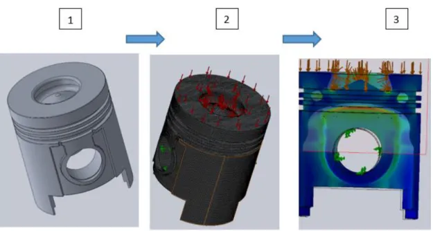
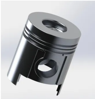
The first step was to choose and design a heavy duty Diesel piston, performed with SolidWorks™ software. The chosen piston was a heavy duty piston, made of aluminium. The next figure, Figure 3.2, shows the 3D (three dimensions) design. There were three reasons to choose this piston:
Heavy duty piston as proposed since the beginning of the dissertation; One part piston, there are heavy duty pistons made by two parts; Data about the piston dimension as well as the piston rod.
Figure 3.2 Heavy duty piston
As it was said before, the main dimensions, such as the height of the inserts of the pistons rings must be the same. The next table, Table 3.1, shows the dimensions that must be kept during the optimisation process. While the Table 3.2 shows the volumetric properties of the piston, the main goal is to reduce 30% of the mass, so the final weight should be around 1.665 kg.
Table 3.1 Main dimensions of the piston Features Dimensions [mm] Lenght 158 Bore 135 Ring Belt [mm] First insert 6 Second insert 4 Third insert 5
Pin Boss diameter 50
Table 3.2 Volumetric properties
Volumetric properties
Mass 2.3791 kg
Volume 8.88× 10⁻⁴ m3
Surface Area 0.157 m2
3.2 Analysis of the slider-crank mechanism
The base of dynamic mechanism operation of engine is slider-crank mechanism, which consist of crankshaft, a connecting rod, a pin and a piston. Combustion pressure transferred from piston (the part merely has reciprocating motion) to the connecting rod (the part has both linear and rotation motion) and finally to the crankshaft (the part that only has rotation motion).
The Figure 3.3, shows a scheme of a slider-crank mechanism with the variables. [15] The x is a representation of the piston displacement, while ω and α are angular velocity and acceleration, respectively. The length of the connecting rod is represented by 𝑙 , 𝜃 is the crank angle, from 0 to 2π rad.
32
Figure 3.3 slider-crank mechanism [16]
The piston has a linear motion in 𝑥 direction predicted with the equation 4.1, where 𝜃the crank angle and r is its radius. The length of the rod is 0.189 m and the crank radius is 0.063 m.
𝑥 = 𝑟(1 − cos(𝜃)) + (𝑛 − √𝑛2 − sin(𝜃)2) (3.1)
The piston linear velocity is computed with equation 3.2, w is the angular velocity in revolutions per minute (rev/min) and N in the angular velocity in rotation per second (rev/s), and n is the ratio between the rod length and the radius of the crank. In this study the angular velocity is 2000 rev/min, which means 33.3 rev/s. C is the pistons stroke.[12]
𝑉𝑝= 𝑉𝑎𝑣𝑒𝑟𝑎𝑔𝑒∙𝜋 2∙ 𝑠𝑒𝑛(𝜃) ∙ (1 + cos(𝜃) ((𝑛2− 𝑠𝑒𝑛(𝜃)2)0.5) (3.2) Where, 𝑉𝑎𝑣𝑒𝑟𝑎𝑔𝑒 = 2𝐶𝑁 (3.3) 𝑁 = 𝑤 60 (3.4)
𝑛 = 𝑙 𝑟
(3.5)
The linear acceleration is calculated through equation 3.6.
𝑎𝑝 = 𝑁2𝑟 ∙ (cos(𝜃) +cos(2𝜃)
𝑛 )
(3.6)
From the equation 3.1 it is possible to compute the positions of the piston between the TDC (top dead centre) and the BDC (bottom dead centre).
Piston position is a measure of how far the piston is down the cylinder from its TDC point. The position of the piston can be determined from the crank angle from Top Dead Centre, knowing the stroke of the engine, length of the connecting rod (𝑙) and the angle of the crank. As the crank Shaft rotates a certain degree, the piston moves a certain distance from Top Dead Centre.
Figure 3.4 Piston position graphic
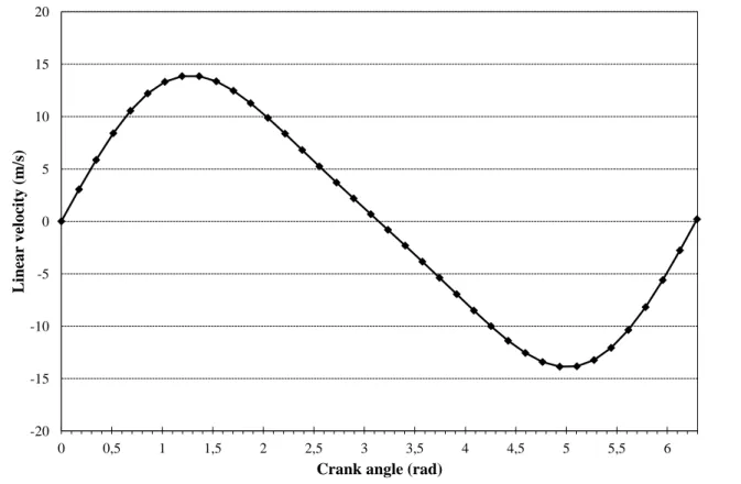
From the equations 3.2, 3.3, 3.4 and 3.5 the linear velocity of the piston was computed. The results are present in Figure 3.5, the maximum of velocity is reached between the TDC and BDC position, and the minimum is reached between the BDC and the TDC position.
0 0,5 1 1,5 2 2,5 3 3,5 4 4,5 5 5,5 6 0 0,05 0,1 0,15 0,2 0,25 0,3
Crank angle (rad)
Pos
ition
(m
34
Figure 3.5 Linear velocity graphic
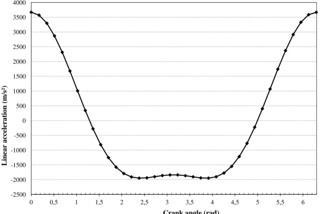
In this study the angular velocity is constant, 2000 rot/min, that means there is no angular acceleration, the Figure 3.6 presents the results achieved through the equations 3.2, 3.3 and 3.8. The maximum of linear acceleration is at TDC position, and the value is 3660 m/s2, then drops until the BDC position where the value of 1948 m/s2 is reached.
0 0,5 1 1,5 2 2,5 3 3,5 4 4,5 5 5,5 6 -20 -15 -10 -5 0 5 10 15 20
Crank angle (rad)
Linea
r velo
city (m
Figure 3.6 Linear acceleration graphic
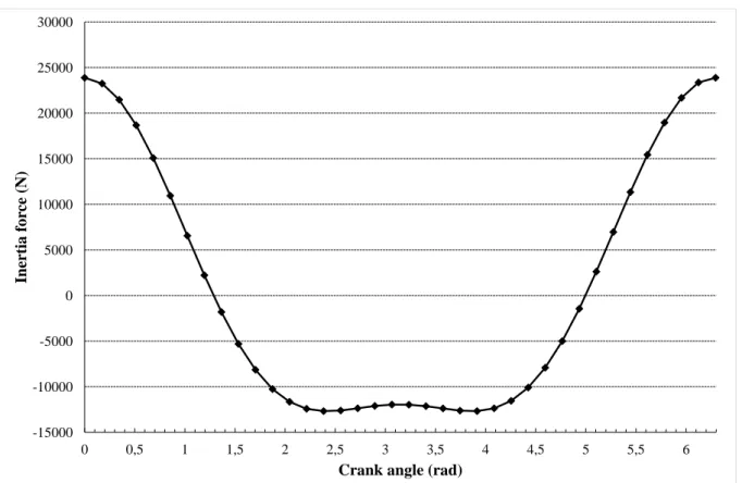
From the second law of Newton, it is possible to calculate the inertia on the piston. The linear acceleration is multiply by a scalar.
𝐹 = 𝑚 ∗ 𝑎 (3.9)
Where,
𝑚 = 𝑚𝑝𝑖𝑠𝑡𝑜𝑛+ 𝑚𝑟𝑜𝑑 (3.10)
The piston mass is 2.379 kg and the rod mass is 4.110 kg, the maximum of inertia force is reached os TDC positon, the value is 23886 N.
0 0,5 1 1,5 2 2,5 3 3,5 4 4,5 5 5,5 6 -2500 -2000 -1500 -1000 -500 0 500 1000 1500 2000 2500 3000 3500 4000
Crank angle (rad)
Linea
r accelera
tion
(m
36
Figure 3.7 Inertia graphic- conventional piston
3.3 Static analysis-conventional piston
The Figure 3.8 shows the main three steps of the simulation. The first one is the material input, the material properties are directly applied to the CAD model. The second step is to create a mesh on the piston. The mesh has to be small enough to cover all the geometries and represents them properly. The final step is to run the analysis, with the main inputs and analyse the results.
0 0,5 1 1,5 2 2,5 3 3,5 4 4,5 5 5,5 6 -15000 -10000 -5000 0 5000 10000 15000 20000 25000 30000
Crank angle (rad)
Inertia
for
ce (
Figure 3.8 Simulation steps
The chosen material on the simulation was an aluminium alloy with surface treatment, 4032 T6. On the two next tables mechanical properties and the percentage of the elements are shown, Table 3.3Table 3.4. [17]
Table 3.3 Mechanical properties of the aluminium alloy 4032 T6
Properties Value
Tensile strength in X (MPa) 380
Yield strength (MPa) 315
Young’s modulus, E (GPa) 70-80
Poisson ratio 0.33
Density( g/cm3) 2.69
Table 3.4 Contents of the aluminium alloy 4032 T6
Element Content (%) Aluminium, Al remainder Silicon, Si 12.5 Magnesium, Mg 1.0 Copper, Cu 0.9 Nickel, Ni 0.9
38
Static analysis is used to calculate how a certain component reacts to some giver conditions, load configurations. For accurate results on complex components, a computer program that uses the Finite Element Method (FEM) is very convenient.
For structural analysis, three steps allows the formation, results and analysis of a computer model of the piston.
Given a meshed model with a set of displacement restraints and loads, the linear static analysis program proceeds as follows: [18]
The program constructs and solves a system of linear simultaneous finite element equilibrium equations to calculate displacement components at each node.
The program then uses the displacement results to calculate the strain components. The program uses the strain results and the stress-strain relationships to calculate the
stresses.
Figure 3.9 Static analysis process [18]
In this study, numerical results were obtained using a finite elements software, SolidWorks™. The first step is to define boundary conditions, in this case the piston is tested during the expansion of the gases on the TDC position. The simulation is done in SolidWorks™ only takes into account the gas pressure applied on the piston crown, 18 MPa, from the state of the art,
Mesh, material properties, restraints and loads
Displacements
Strains
Table 2.1.The pressure is applied normal to the surface, see Figure 3.10. The results obtained from the simulation will show how the tensions spread on the piston.
Piston pin hole is constrained by displacement and symmetry, fixed feature, this restraint type sets all translational degrees of freedom to zero.
Figure 3.10 Constraint feature- conventional piston
3.3.1 Mesh
In meshing a part or an assembly with solid elements, the software generates one of the following types of elements based on the active mesh options for the study:
Draft quality mesh. The automatic mesher generates linear tetrahedral solid elements. High quality mesh. The automatic mesher generates parabolic tetrahedral solid
elements.
Linear elements are also called first-order, or lower-order elements. Parabolic elements are also called second-order, or higher-order elements.
A linear tetrahedral element is defined by four corner nodes connected by six straight edges. A parabolic tetrahedral element is defined by four corner nodes, six mid-side nodes, and six edges. [18]
The Figure 3.11shows schematic drawings of linear and parabolic tetrahedral solid elements. In general, for the same mesh density (number of elements), parabolic elements yield better results than linear elements because:
40
They represent curved boundaries more accurately, and
They produce better mathematical approximations. However, parabolic elements require greater computational resources than linear elements.
Figure 3.11 Types of Solid mesh [20]
For structural problems, each node in a solid element has three degrees of freedom that represent the translations in three orthogonal directions. The software uses the X, Y, and Z directions of the global Cartesian coordinate system in formulating the problem.[19]
In Figure 3.12 presents some of the mesh details used on the static study, the percentage of cells with aspect ratio lower than 3 is 99%, which means the ratio between the longest and the shortest side of the cells is 3 or less, ideally this ratio should be near 1 to ensure better results.[20]
Figure 3.12 Mesh details
3.3.2 Maximum von Mises Stress Criterion
The maximum von Mises stress criterion is based on the von Mises-Hencky theory, also known as the shear-energy theory or the maximum distortion energy theory.
In terms of the principal stresses σ1, σ2, σ3, the von Mises stress is expressed as:
𝜎𝑣𝑜𝑛𝑀𝑖𝑠𝑒𝑠 = √[(𝜎1− 𝜎2)2+ ((𝜎2− 𝜎3)2+ (𝜎1− 𝜎2)] ∙
1 2
(3.11)
The theory states that a ductile material starts to yield at a location when the von Mises stress becomes equal to the stress limit. In most cases, the yield strength is used as the stress limit. However, the software allows you to use the ultimate tensile or set your own stress limit.
𝜎𝑣𝑜𝑛𝑀𝑖𝑠𝑒𝑠 ≥ 𝜎𝑙𝑖𝑚𝑖𝑡 (3.12)
Yield strength is a temperature-dependent property. This specified value of the yield strength should consider the temperature of the component. The factor of safety at a location is calculated from: [21]
42
3.3.3 Stress results- Gas pressure
The following figure, Figure 3.13, shows the simulation results. As it is possible to understand the highest stress load is around 182 MPa, which is under the yield strength of the material (315 MPa). This value will be the reference to the design optimisation, which means that the maximum stress of the optimised piston cannot be greater than the maximum stress of the conventional design, around 182 MPa.
Figure 3.13 Static analysis- conventional piston
As it is possible to observe, in Figure 3.14, the maximum stress appears on the top of the piston boss, between the transition of the piston crown and the main body of the component, where the geometry loses its continuity that is why stress risers happened. Those areas are called critical areas.
Figure 3.14 Maximum stress of the static analysis- conventional piston
The Figure 3.15 shows a different plot of these simulation, the displacement over the piston. As it is shown on Figure 3.15, the maximum displacement occurs on the lower part of the piston, due to the input of the constraints on the simulation. The piston body and the pin boss are fixed. The maximum displacement is 8.270×10⁻² mm, and in placed on the piston skirt and on the top
of the piston. The maximum displacement are placed on the opposite direction of the pin bosses due to the fixed feature. The displacement is bigger on the lower part of the skirt because of its thickness, the lower part is thinner than the upper part.
Figure 3.15 Displacement results- conventional piston
The Figure 3.16 shows the factor of safety among the piston. This factor is a relationship between the yield strength and the results from each location, see section 3.3.2. As it was
44
expected the factor is always greater than 1, as it was present on the static results the highest stress is about 1.7 times lower than the yield strength and it is represented by the factor of safety. The lower factor is placed where the stresses are greater and the other way around is true.
Figure 3.16 Factor of safety- conventional piston
3.3.4 Static analysis results- Inertia
The inertia was computed through the acceleration results, see Figure 3.7. The highest value was the input of this simulation, the results are present in Figure 3.17. The maximum stress is located on the outside of the piston boss, 171 MPa. The force, which was calculated on the section 3.2, is applied on the pin boss.
3.4 Thermal analysis
When simulating operation conditions of a piston, it is important to compute the heat transfer between the walls of the piston to the cylinder and the heat transfer to the combustion chamber. It is important to perform a thermal analysis on the piston in order to track and control the thermal stresses and deformations.
The thermal analysis of the piston is important from different points of views. First, the highest of any point should not exceed 66% of the melting point temperature of the alloy 4032 T6, between 532 and 571oC. [22]
A thermal analysis of the piston was performed. The thermal boundary conditions have been applied to the 3D model. Temperature distribution of piston was obtained using four different boundary conditions:
Heat transferred from the combustion gases to the piston crown; Heat transferred to the engine oil from the outside of the piston; Heat transferred to the engine oil from the underside of the piston; Heat transferred form the cooling gallery to the oil.
The next table shows the main properties of the oil 15W40, a typical oil used on heavy duty engines. Those properties were used the compute the heat transfer coefficient all the inputs between the wall of the cylinder and the piston.[23]
Table 3.5 oil properties
Oil properties, 15W40
Specific heat 𝑪𝒑 2.19 kJ/kgK
Thermal conductivity 𝒌 0.137 W/mK
Kinetic viscosity 𝜸 14.1×10⁻⁶ m2/s
The Table 3.6 shows the main properties of the impinging jet. Those properties were used to compute the heat transfer coefficient the oil the remains the inside of the piston cooled and the underside of the piston.[23]
Table 3.6 Jet properties
Jet properties
Diameter 2.2×10⁻³ m
46
The piston used for the present simulation is a piston from heavy duty transportations and the follow table, Table 3.7, presents its main data for the simulation.
Table 3.7 Piston information
Piston data
Length 158×10-3 m
𝒗𝒎𝒆𝒅 9 m/s
3.4.1 Boundary conditions
It considers that a heat transfer between the cylinder wall and the piston is similar as in between two parallels plates, see Figure 3.18.[24] The conduction coefficient was computed with equation 3.14.
Figure 3.18 Scheme of the heat transfer between the cylinder and the piston wall
ℎ =𝑘
𝑦 (3.14)
Where 𝑦 is the oil thickness, see Figure 3.18 , which is 70 × 10−6𝑚.
The software does not allow a conduction input, so the value obtained was insert as a convection coefficient.
The second input is related to the cooling system. The convection coefficient of the inner side is computed trough a system of jet impingement, demonstrated on Figure 3.19. Basically, the oil injector troughs oil to the inner surface of the system. The calculations were made with a 𝑧0
constant as well as the velocity of the piston.
The piston is cooled in two different ways. Part of the heat is driven through the segments to the liner and finally to the coolant. The greater part, though, is transferred to the oil. In the
engine under normal operating conditions the oil. With the temperature of 120℃, is sprayed to the inner part of the piston, see Figure 3.19. A numerical model was developed using finite element methods for studying the oil jet cooling of the piston. The jet, diameter on this study, is 2.2 mm on Table 3.8.
Figure 3.19 The coordinate system used for the notations for oil jet cooling [23]
𝑁𝑢 𝑁𝑢0 = [1 + 𝑓 ( 𝑟 𝑑) −9 ] 0.11 (3.15) 𝑓 (𝑟 𝑑) = 𝑎𝑒𝑏( 𝑟 𝑑) (3.16) 𝑅𝑒 = 𝜌𝑈𝑥 𝜇 = 𝑈𝑙 𝛾 (3.17) 𝑁𝑢0 = 2.67𝑅𝑒0.567𝑃𝑟0.4( 𝑧0 𝑑)−0.336( 𝑣 𝑑)−0.237 (3.18) 𝑣 = 𝑣𝑗𝑒𝑡− 𝑣𝑝𝑖𝑠𝑡𝑜𝑛 (3.19)
48
Table 3.8 Values of a and b [23]
d [mm] a b 2.2 1.13 -0.23 2.3 1.141 -0.2395 4.1 1.34 -0.41 5.8 1.48 -0.56 8.9 1.57 -0.7
On the combustion chamber the heat transfer was compute trough the equation (3.20). [12]
ℎ = 3.26𝑝0.8𝑣0.75𝐷−0.2𝑇−0.465 (3.20)
The pressure is the gas pressure, 18 MPa and the velocity is the piston average velocity which is 9 m/s. TheTable 3.9, shows the different values of heat convection coefficient, since the velocity of the piston and the gas pressure is the same.
Table 3.9 Different values of h with fluctuations on the temperature
T(℃) h (W/m2k) 1500 167.67 1750 186.33 2000 204.54 2250 222.34 2500 239.80
Both of the thermal studies, either the conventional or the optimised piston, are made with the temperature of combustion of 1750℃. The other values will be studied, but only the maximum of temperatures will be present, the results will be present on the last section of this chapter.
3.4.2 Thermal analysis results- Conventional piston
The figure Figure 3.20 shows the thermal analysis results. As it possible to observe the highest temperature is located on the edge of the piston crown, 323℃. The temperature decreases on the ring belt and reaches the minimum, 120℃, on the skirt.
Figure 3.20 Temperature distribution in the piston- conventional piston
The Figure 3.21 represents a plot of the thermal analysis, where only a transversal cut of the piston is shown. This plot was performed in order to show the different temperatures on the piston ring zone. As we can see, the first ring reaches a, approximately, 240 ℃ then drops until 217 ℃ on the second ring, and the temperature of the third ring is around 198℃. So, we have a decrease of temperatures of the first to the second ring of 23 ℃ and the second to the third of 19℃, which means that the cooling gallery, placed between the first and the second ring, is cooling that region. Then, the temperature drops until 120 ℃ when reaches the skirt area.
![Figure 2.9 Phase diagram FeC [6]](https://thumb-eu.123doks.com/thumbv2/123dok_br/17658280.824337/35.892.202.685.124.503/figure-phase-diagram-fec.webp)
![Figure 2.10 Representation of a Steel and an Al piston, on the left a Steel piston and on the right an Al piston [9]](https://thumb-eu.123doks.com/thumbv2/123dok_br/17658280.824337/36.892.294.597.120.443/figure-representation-steel-piston-steel-piston-right-piston.webp)
![Figure 2.12 Salt core cooling channel on the left, piston with cooled ring carrier on the right.[6]](https://thumb-eu.123doks.com/thumbv2/123dok_br/17658280.824337/38.892.158.733.242.523/figure-salt-cooling-channel-piston-cooled-carrier-right.webp)
![Figure 2.21 Piston with wear resistant inserts in the first groove [8]](https://thumb-eu.123doks.com/thumbv2/123dok_br/17658280.824337/49.892.305.587.105.293/figure-piston-wear-resistant-inserts-groove.webp)
![Figure 3.3 slider-crank mechanism [16]](https://thumb-eu.123doks.com/thumbv2/123dok_br/17658280.824337/54.892.286.619.158.512/figure-slider-crank-mechanism.webp)