1 Introduction
Passive fire protection materials insulate steel structures from the effects of the elevated temperatures that may be gen-erated during a fire. They can be divided into two types, non-reactive, of which the most common types are boards and sprays, and reactive, of which intumescent coatings are an ex-ample. They are available as solvent- or water-based systems applied up to approximately 3 mm. One problem associated with the use of such systems is the adhesion of the charred structure to the steel element during and after a fire. It is very important that the char remains in the steel surface to ensure fire protection.
Intumescent chemistry has changed little in recent years, and almost all coatings are largely based on the presence of similar key components. The chemical compounds of intu-mescent systems are classified into four categories: a car-bonisation agent, a carbon rich polyhydric compound that influences the amount of char formed and the rate of char formation; an acid source, and a foaming agent, which during their degradation release non-flammable gases such as CO2
and NH3[1].
Activated by fire or heat, a sequential chemical reaction between several chemical products takes place. At higher temperatures, between (200–300) °C, the acid reacts with the carboniferous agent. The formed gases will expand, begin-ning the intumescence in the form of a carbonaceous char.
Different models handle the intumescent behaviour with char-forming polymers as a heat and mass transfer prob-lem. Other existing models provide a suitable description regarding the intumescence and char formation using ki-netic studies of thermal degradation, accounting the complex sequence of chemical reactions, thermal and transport phe-nomenon [2–5].
Due to the thermal decomposition complexity of intumes-cent coating systems, the models presented so far are based on several assumptions, the most relevant being the consider-ation of one-dimensional heat transfer through material, temperature and space independent thermal properties and the assumption of a constant incident heat flux where the
heat losses by radiation and convection are ignored [3]. Some authors also assume that the thermochemical processes of intumescence occur without energy release or energy absorp-tion [6]. Results show that the insulaabsorp-tion efficiency of the char depends on the cell structure, and the low thermal conductiv-ity of intumescent chars results from the pockets of trapped gas within the porous char which act as a blowing agent to the solid material.
In a previous work considering the results obtained from coated steel plates tested in a cone calorimeter, the authors studied intumescence as a single homogeneous layer. The steel temperature variation was considered, and with the intumescence thickness time variation an inverse one-dimen-sional heat conduction problem (IHCP) was applied to determine the intumescence effective thermal conductivity and thermal resistance [7].
This work presents an experimental study to assess the performance of water-based intumescent paints used as a pas-sive fire protection material. These tests were performed in a cone calorimeter, in steel plates coated with two different paints, three dry film thicknesses and considering two differ-ent radiant heat fluxes. During tests, among other quantities, the steel temperature, the intumescence mass loss and thick-ness variation were measured. A numerical model is also presented to study the intumescence behaviour. The paint thermal decomposition numerical model is based on the conservation equation of energy, mass and momentum.
2 Experimental tests performed in the
cone calorimeter
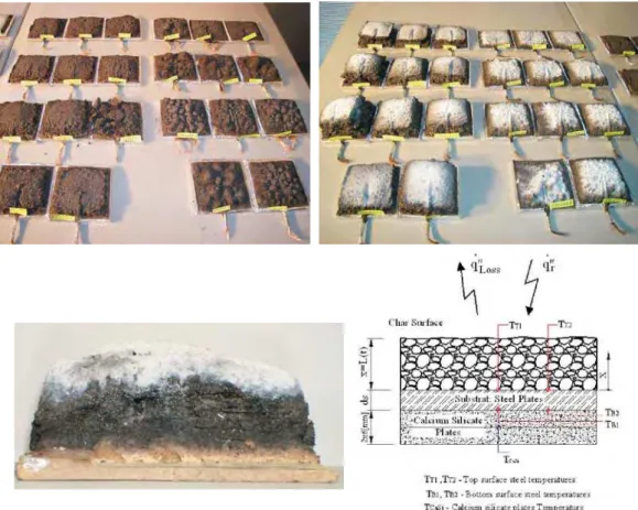
To assess the performance of two commercial water-based intumescent paints, a set of experimental tests was performed in a cone calorimeter, see Fig. 1 and Fig. 2. The steel plates are 100 mm squared and 4, 6 mm thick, coated on one side with different dry film thicknesses and tested in a cone calorimeter, as prescribed by the ISO5660 standard [8]. Temperatures are measured by means of four thermocouples, type k, welded to the plate on the heating side and on the opposite side, at two different positions. The samples were weighed before and
af-Decomposition of Intumescent Coatings:
Comparison between a Numerical
Method and Experimental Results
L. M. R. Mesquita, P. A. G. Piloto, M. A. P. Vaz, T. M. G. Pinto
An investigation of two different intumescent coatings used in steel fire protection has been performed to evaluate their efficiency. A set of ex-perimental tests is presented. They were conducted in a cone calorimeter, considering different thicknesses and heat fluxes. Among other quantities, the steel temperature and the intumescence thickness variation were measured. A numerical model for the paint decomposition is also presented. Based on the intumescence experimental value, the model is able to provide a reasonably good prediction of the steel tempera-ture evolution.
ter being coated, to allow for the initial coating mass. The dry thickness was also measured in 16 different points. The mean values and the standard deviation are presented in Fig. 1.
Between the steel plate and the sample older, two silicate plates were used to put the specimen in place and also a ther-mocouple was placed to measure its temperature variation. The distance between the sample surface and the heater re-mained unchanged, at approximately 60 [mm]. This means
that with the increasing intumescence the top of the sample came closer to the cone surface. Due to the large volume of re-sults, only a set of samples will be referenced in this paper.
Experimental results
The temperature evolution in a steel plate without pro-tection was also tested to attain the efficiency of this fire protection. The measured temperatures are presented in
Specimens identification
Initial Mass [g]
Final Mass [g]
Coating Mass [g]
DFT [?m]
ó (SD) [?m]
Higher [?m]
Smaller [?m] A 35 4 0.5 1-3 363.77 371.28 7.51 545 40.6 601 478
A 35 4 0.5 2-3 363.82 369.98 6.16 615 51.5 695 504
A 35 4 0.5 3 364.54 373.19 8.65 528 60.4 624 427
A 35 4 1.5 1 361.10 387.74 26.64 1670 107 1860 1500
A 35 4 1.5 2 362.17 388.06 25.89 1610 72.2 1750 1500
A 35 4 1.5 3 361.38 385.42 24.04 1450 84.9 1580 1280
A 35 4 2.5 1-2 362.81 400.38 37.54 2530 165 2800 2240
A 35 4 2.5 2 365.81 407.89 42.08 2590 122 2790 2310
A 35 4 2.5 3-2 363.49 404.38 40.89 2680 179 2920 2370
A 75 4 0.5 1 363.46 372.34 8.88 549 60.3 639 425
A 75 4 0.5 2-2 363.58 371.33 7.75 586 36.3 651 538
A 75 4 0.5 3 368.44 377.85 9.41 582 48.6 657 466
A 75 4 1.5 1 369.59 394.82 25.23 1510 83.7 1660 1390
A 75 4 1.5 2 371.11 396.24 25.13 1530 87.7 1720 1380
A 75 4 1.5 3 364.87 391.13 26.26 1620 98.7 1820 1450
A 75 4 2.5 1 366.97 407.71 40.74 2590 122 2760 2330
A 75 4 2.5 2 365.11 404.90 39.79 2590 134 2800 2350
A 75 4 2.5 3 370.60 410.77 40.17 2530 167 2810 2260
A 35 6 0.5 1 527.37 535.05 7.68 476 33.1 518 403
A 35 6 2.5 1 526.65 565.71 39.06 2420 150 2610 2130
A 75 6 0.5 1 522.90 530.58 7.68 494 33.9 561 434
A 75 6 2.5 1 525.71 564.89 39.18 2490 112 2670 2290
Specimens identification
Initial Mass [g]
Final Mass [g]
Coating Mass [g]
DFT [?m]
ó (SD) [?m]
Higher [?m]
Smaller [?m] B 35 4 0.5 1 366.73 375.36 8.63 571 41.6 665 506
B 35 4 0.5 2 365.38 374.88 9.50 626 38.6 698 563
B 35 4 0.5 3 364.95 373.95 9.00 603 49.5 710 481
B 35 4 1.5 1 365.63 390.10 24.47 1510 70.2 1610 1400
B 35 4 1.5 2 365.82 391.42 25.60 1570 64.1 1670 1470
B 35 4 1.5 3 364.80 390.67 25.87 1580 66.5 1710 1470
B 35 4 2.5 1 365.49 409.85 44.36 2640 90.9 2750 2460
B 35 4 2.5 2 366.29 409.12 42.83 2560 89.0 2660 2400
B 35 4 2.5 3 366.40 407.77 41.37 2510 85.7 2660 2350
B 75 4 0.5 1 362.92 371.94 9.02 581 35.9 653 518
B 75 4 0.5 2 366.00 375.97 9.97 662 53.9 817 599
B 75 4 0.5 3 367.53 377.53 10.00 631 31.2 707 583
B 75 4 1.5 1 366.27 390.71 24.44 1530 79.5 1720 1440
B 75 4 1.5 2 364.69 389.63 24.94 1550 67.8 1690 1450
B 75 4 1.5 3 359.09 384.05 24.96 1560 74.9 1740 1450
B 75 4 2.5 1 359.79 399.66 39.87 2520 211 2840 2170
B 75 4 2.5 2 364.28 405.30 41.02 2520 91.4 2690 2350
B 75 4 2.5 3 364.80 404.97 40.17 2490 126 2760 2340
B 35 6 0.5 1 528.60 537.10 8.50 533 56.7 663 431
B 35 6 2.5 1 528.91 571.74 42.83 2570 105 2720 2360
B 75 6 0.5 1 525.47 534.86 9.39 607 65.9 799 528
B 75 6 2.5 1 529.04 570.00 40.96 2610 75.8 2760 2500
Fig. 1: Set of experimental tests. Reference: Paint/Heat Flux/Steel Thick./Dry Thick/Test N°
Fig. 2: Coated steel plates, with fixed thermocouples. Tested samples at 35 kW/m2and at 75 kW/m2, reference and position of the
Fig. 3 for a radiant heat flux of 35 KW/m2and then resetting the cone to 75 KW/m2.
Fig. 4 represents the mass loss of each sample and shows a variation almost linear with time, mainly for a heat flux of 35 kW/m2.
Using discrete frames obtained from a digital camera during the tests, and by image processing techniques using Matlab, the intumescence development was measured over time. Fig. 5 presents the intumescent development (free Fig. 3: Measured temperature in the steel plate without
protection
Fig. 4: Measured mass loss with time
Fig. 5: Intumescence thickness mean values of four central measurements
boundaryL(t)) for specimens with paint A and B, different
thicknesses and radiant heat fluxes.
Higher intumescence may be observed in the sample right region coincident to the thermocouple wire position re-sponsible for coating accumulation. The presented values are mean values determined from four central measures.
The figures show that for the lower heat flux the intu-mescence becomes stable, but for the higher heat flux it continues to increase. Coating A presents a higher expansion at the initial stage compared to coating B. For longer periods of exposure coating B continues to expand.
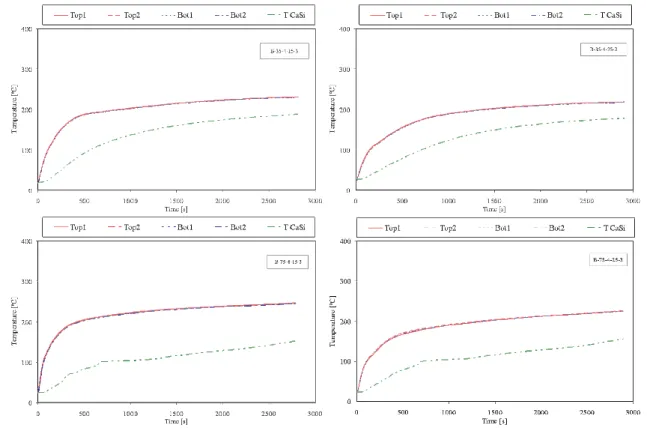
The steel temperature profiles and temperatures in the middle of the silicate plates are reported in Fig. 6 and Fig. 7. Measured values from the thermocouples welded to the bot-tom of the plate are very close to the temperatures at the top. For the same heat flux, the time to reach the same tempera-ture increases with the increase of the dry thickness.
The behaviour is very similar for both coatings, but for all cases the time to reach, e.g., a temperature of 200 °C is always higher when paint B is used. For these conditions it gives im-proved fire protection.
3 Mathematical model of the
intumescence behaviour
To determine the temperature field in an intumescent material, it is necessary to solve a phase transformation prob-lem with two ore more moving boundaries that characterize its state, initial, softened and carbonaceous char. Different methodologies can be found in the literature to model the thermal decomposition of a polymer or polymer based mate-rials. The methodology followed in this work was to consider
that the decomposition occurs not only at the outside surface but also inside, for temperatures above the pyrolysis tempera-ture, T
p. In this case the moving boundary regression rate
must be determined considering the motion of the whole do-main. This strategy implies that a mass diffusion term needs to appear in the energy equation due to its motion. This term was disregarded due to the small thickness of the virgin layer for this types of applications, about 1–3 mm.
Considering a first order reaction, the mass loss is given by
&( ( , )) ( , )
m T x t
t A e
E RT x T
= =
-¶r
¶ r
v
v 0
0
for T³Tp, (1)
wherem&is the local mass loss kg×m-3×s-1,T(x,t) is the temper-ature at pointxat instantt,A0is the pre exponential factor [s-1], E0 the activation energy [J×mol-1], and Rthe univer-sal gas constant [J×mol-1×K-1
]. The position of the moving boundary is obtained by summing all the mass loss and divid-ing by the specific mass.
The energy equation for the steel and virgin layers is based on the one-dimensional conduction heat equation.
The conservation equation for the solid virgin material phase is given by
¶r
v v
v v V
t w V
md
= -& , (2)
wherew&md
v represents the destruction rate of virgin material per unit volume, originated by the thermal decomposition. The virgin material decomposition produces a fraction of gas, equal to the porosity,j, and a solid char fraction equal to
The formation rate of char and gas mass is:
& ( ),
&
w A s t
t w p p gas c v v char c d d
= -æ -è ç ç ö ø ÷ ÷ = - - -1 1 1 r
r c r
r
rv v
d d æ è ç ç ö ø ÷ ÷ é ë ê ê ù û ú ú
c r A s t
t
( ) .
(3)
crepresents the fraction of the bulk density difference
be-tween the virgin and char materials that is converted to gas. In this study the value used wasc=0.66, [9].
The conservation of gas mass equation is given by Eq. (4).
¶ r j
r j ¶ 
( g ) g &g
t V
V t
m x
+ + ¢¢ =0. (4)
In the previous equation,¶V ¶trepresents the
intumes-cence rate. The gas mass flux,m&¢¢
g, is calculated accordingly to
Darcy’s law and it is assumed that the gases present in the in-tumescent material behave as a perfect gas. The thermody-namic properties are related by the ideal gas law and, assum-ing that the gas is a mixture of 50wt%CO
2and 50wt%H2O,
the generated gas molar mass used in the model M
g is
31 g/mol.
The conservation of gas mass equation with the Darcy and the ideal gas laws combined can be used to give a differential equation for the pressure inside the intumescence. In the numeric calculations, the intumescence rate is assumed to be known, provided by experimental results, so the pressure calculation is disregarded on the assumption that the internal pressure is constant and equal to the atmospheric pressure. An energy equation for the conservation of energy within the intumescence zone can be obtained by combining the energy equation for the gases with that of the solid char material. The equation for the conservation of energy per unit bulk volume can be written as:
(r ) ¶ (& )
¶ ¶ ¶ ¶ ¶ ¶ ¶ Cp T
t x m T Cp x k
T
x CpT
eff + ¢¢g g g = eff
æ è
ç ö
ø
÷ - ¶r ¶ r ¶ ¶ t Cp T V V t -( )eff ,
(5)
where
(rCp)eff =j rgCpg +(1-j r) cCpc
and
keff =jkg+(1-j)kc.
The effective thermal conductivity for the intumescence bulk material, including gas and char, is equal to the thermal conductivity of the gas per unit bulk volume, plus that of the solid material. The same thing applies to the effective heat capacity.
In the steel plate back surface we assume an adiabatic boundary condition, and at the boundary steel/virgin layers we assume a perfect thermal contact. At the moving front, the boundary conditions are:
k T
x q T T h T T T s t t T
k
r a a
v p
¶ e es
= &¢¢ - ( 4- 4)- ( - ) ( ( ), )< ,
c for v p ¶ ¶ ¶ ¶ T x k T
x QH T s t t T
- - = =
c for ( ( ), ) ,
(6)
in whichQHis the heat flux due to the endothermic decom-position of the virgin material, given by QH = -hprvs t&( ), where hp represents the decomposition enthalpy. A wide range of values are reported in the literature for the heat of
pyrolysis, ranging from a few units to units of millions. The value used in the calculations was 50 J/kg.
The intumescent coating specific mass was measured by the pycnometer method given a value of 1360 and 1250 kg/m3for the virgin coating and a value of 692.4 and 450 kg/m3for the char material, for paints A and B, respec-tively. The steel properties are assumed constant, with a specific heat value of 600 J/kg×K and a specific mass equal to
7850 kg/m3.
The mathematical model is based on the following major simplifying assumptions: there is no heat between gas and char, the thermophysical properties and the pressure at both layers are constant.
The solution method was implemented in a Matlab rou-tine using the Method Of Lines (MOL), [10], and the integra-torode15sto solve the set of ordinary differential equations.
The temperature field is determined by the steel and vir-gin energy equations. When the front reaches the pyrolysis temperature, equal to 250 °C, it starts to decompose and to move. Then the moving front rate is determined and the intumescence forms. The position the free boundary is set equal to the experimental results and the intumescence tem-perature field is determined. In each time step the virgin and char layers are remeshed.
The input parameters are listed as follows:
kv =0.5 W×m-1×K-1;kc=0.1 W×m-1×K-1;
Cpv =2600 J×kg-1×K-1;Cp
c=3000 J×kg
-1× K-1;
hc=20 W×m2×K-1
;e=0.92;
Tp=525 K;A0=4.67 e12×s-1.
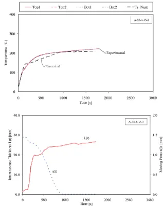
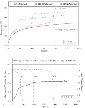
Two case studies are presented in Fig. 8 and Fig. 9. In the first study, the steel temperature variation and the moving front position are determined based on a value of the
acti-Fig. 8: Comparison of measured and computed steel
vation energy equal to E
0=125K×J×mol
-1
. The numerical results follow the experimental values reasonably well. The major differences occur at intermediate times, probably be-cause a transition state of molten polymer was not considered. Both the determined steel temperatures and the moving front are strongly dependent on the activation energy that de-fines the amount of mass loss of virgin paint, as presented in Fig. 9. It must be said that the value used in the simulations was obtained from the literature, but the correct values of both paints are needed. The reaction kinetics parameters can be obtained from thermogravimetric analysis.
Acknowledgments
The authors acknowledge financial support from the Portuguese Science and Technology Foundation, project PTDC/EME-PME/64913/2006, “Assessment of Intumescent Paint Behaviour for Passive Protection of Structural Elements Submitted to Fire Conditions”, and fellowship SFRH/BD/ 28909/2006. The authors also acknowledge the contribution from the paints producers: CIN, Nullifire.
References
[1] Duquesne, S., Bourbigot, S., Delobel, R.: ”Mechanism of Fire Protection in Intumescent Coatings”. European
Coatings Conference: Fire Retardant Coatings II, Berlin, 2007.
[2] Staggs, J. E. J.: “A Discussion of Modelling Idealised Ab-lative Materials with Particular Reference to Fire Test-ing”,Fire Safety Journal, Vol.28(1997), p. 47–66. [3] Moghtaderi, B., Novozhilov, V., Fletcher, D., Kent, J. H.:
“An Integral Model for the Transient Pyrolysis of Solid Materials”.Fire and Materials, Vol.21(1997), p. 7–16. [4] Lyon, R. E.: “Pyrolysis Kinetics of Char Forming
Poly-mers”. Polymer Degradation and Stability, N1, Vol. 61
(1998), p. 201–210.
[5] Jia, F., Galea, E. R., Patel, M. K.: “Numerical Simulation of the Mass Loss Process in Pyrolizing Char Materials”.
Fire And Materials, N1, Vol.23(1999), p. 71–78. [6] Kuznetsov, G. V., Rudzinskii, V. P.: “Heat Transfer in
In-tumescent Heat- and Fire-Insulating Coatings”,Journal of Applied Mechanics and Technical Physics, Vol.40(1999), No. 3.
[7] Mesquita, L. M. R., Piloto, P. A. G., Vaz, M. A. P., Pinto, T.: “Numerical Estimation For Intumescent Thermal Protection Using One-Dimensional IHCP”.
WCCM8-ECCOMAS 2008, Venice, Italy, June 30–July 5, 2008. ISBN 978-84-96736-55-9.
[8] ISO 5660-1:2002: Reaction-To-Fire Tests – Heat Release, Smoke Production and Mass Loss Rate. Part 1: Heat Release Rate (cone calorimeter method), International Organization for Standardization, 2002.
[9] Lautenberger, C.:A Generalized Pyrolysis Model for Com-bustible Solids, Ph.D. thesis, University of California at Berkeley, Berkeley, CA, 2007.
[10] Wouwer, A. V, Saucez, P., Schiesser, W. E.: “Simulation of Distributed Parameter Systems Using a Matlab-Based Method of Lines Toolbox: Chemical Engineering Applications”, Ind. Eng. Chem. Res. Vol. 43 (2004), p. 3469-3477.
Luís M. R. Mesquita e-mail: [email protected] Paulo A. G. Piloto Tiago M. G. Pinto
Applied Mechanics Department Polytechnic Institute of Bragança Portugal
Mário A. P. Vaz Faculty of Engineering University of Porto Portugal