L_ ~Aash~ I ' " -~,
-- -- -- -- - - ~-- - - ~-- --
-File Vitw Conttol Htlp
11 Conferencia Nacional
em medinica de fluidos, termodinamica e energia
Apoio:
FCT
Fund•~o prr.o • Cienm c • Ttcnologi•r"o " '
Patrocinio:
MRA
INSTRUMENTA<;AO
APMIAC
H ~
G
Caixa Geral
Cl)
de Depositos
-- - - - --
--l\IJ:: L \ I f. IL\11 (
t
-... ~
em mecanica de fluidos, termodinamica e energia
Aetas da Il l Conferi'mcia Nacional em Mecanica dos Fluidos, Termodinamica e Energia (MEFTE - BRAGANC,:A 09), artigos completos.
Au t o •e ~ da e di ~o: Fernando Pinho, Pedro Coelho, Paulo Ol iveira, Paulo Pilol o
ISDN: 978·989·96264-1-6
[ d ito1a: A ssoci a ~o Portuguesa d e Mec.lnica Te orica A plicada e Computacional (APMTAC)
INTUMESCENT COATING MODELLING BASED ON SMALL SCALE
EXPERIMENTAL TESTS
Luís M.R. Mesquita1, Paulo A.G. Piloto1, Mário A.P. Vaz2
1
Polytechnic Institute of Bragança, Applied Mechanics Department, Campus Sta Apolónia, Ap. 1134, 5300-857 Bragança, Portugal
email: [email protected] http://www.ipb.pt
2
Faculty of Engineering of the University of Porto, Rua Dr Roberto Frias, S/N, 4200-465 Porto, Portugal
Abstract
An investigation of two different intumescent coatings used in steel fire protection has been performed to evaluate their efficiency. Among other quantities, the steel temperature and the intumescence thickness variation were measured. A mathematical model for the intumescent coating is developed. It considers the coating decomposition and models the protection by two layers, the reacted and the unreacted layer. A comparison between the experimental results and the ones obtained from the numerical model is presented.
Key-words: Fire Protection; Intumescent Coatings; Cone Calorimeter; Heat Transfer; Thermal
Decomposition
1
Introduction
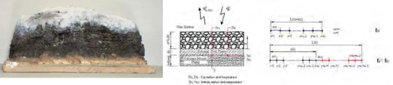
Thin film intumescent coatings are mostly used in the civil construction industry to increase the fire resistance requirements prescribed by the structural fire design codes. They are applied essentially to structural elements with inadequate fire behaviour, like the case of steel and aluminium structures. An intumescent coating when submitted to fire starts to bubble and swells to form a carbonaceous, porous, low-density char, reducing the heat transfer to underlying virgin material layer and therefore to the substrate.
The performance of two commercial water-based intumescent paint were assessed by a set of experimental tests, conducted in a cone calorimeter, which enables the mass loss rate calculation, the substrate temperature and the intumescence thickness variation with time, [1].
A numerical model is established with the conservation equation of energy for the substrate, virgin and char layers, the conservation of mass of gas and solids and the transport of gas through the char is modelled using the empirical Darcy’s law approximation. The model allows knowing the moving boundary and the free boundary locations and therefore the overall intumescence thickness with time.
The paper presents the model development, the numeric treatment of the differential equations and, based on the intumescence thickness variation, the steel temperature comparison between the numeric and the experimental results.
2
Results from the cone calorimeter tests
To assess the performance of two commercial water-based intumescent paints a set of experimental tests was performed in a cone calorimeter as prescribed by the standard ISO5660, [2]. The steel plates were coated in one side with different dry film thicknesses (0.5, 1.5, 2.5 [mm]) and tested with two radiant heat fluxes: 35 [kW/m2] and 75 [kW/m2]. During tests, among other quantities, steel temperature, intumescence mass loss and thickness variation were measured. Additional results and a detailed presentation of the experimental work can be found in [1].
Fig. 1. Steel plate temperatures for 4 [mm] specimens,
with coating A, tested with heat a flux of 35 [kwm-2].
Fig. 2. Steel plate temperatures for 4 [mm] specimens,
with coating B, tested with heat a flux of 35 [kwm-2].
Fig. 3. Steel plate temperatures for 4 [mm] specimens,
with coating A, tested with heat a flux of 75 [kwm-2].
Fig. 4. Steel plate temperatures for 4 [mm] specimens,
with coating B, tested with heat a flux of 75 [kwm-2].
The intumescent development (free boundary L(t)) is represented in Fig. 5 to Fig. 8 for specimens with paint A and B, with different thicknesses and radiant heat fluxes. The presented values are mean values of four central measurements in the distance between the thermocouples. The figures show that for the lower heat flux the intumescence becomes stable but for the highest it continues to increase. The coating A have a higher expansion at the initial stage compared to the coating B. For longer periods of exposure coating B continues to expand.
0 5 10 15 20 25 30
0 500 1000 1500 2000 2500 3000
Time [s]
In
tu
m
e
sc
e
n
c
e
T
h
ic
k
n
e
ss
[
m
m
]
A354051_3
A354052_3
A354053
A354151
A354152
A354153
A354251_2
A354252
A354253_2 0
5 10 15 20 25 30
0 500 1000 1500 2000 2500 3000
Time [s]
In
tu
m
e
sc
e
n
c
e
T
h
ic
k
n
e
ss
[
m
m
]
B354051
B354052
B354053
B354151
B354152
B354153
B354251
B354252
B354253
Fig. 5. Coating A intumescence development for 4
[mm] specimens tested with a heat flux of 35 [kwm-2].
Fig. 6. Coating B intumescence development for 4
0 5 10 15 20 25 30
0 500 1000 1500 2000 2500 3000
Time [s]
In
tu
m
e
sc
e
n
c
e
T
h
ic
k
n
e
ss
[
m
m
]
A754051
A754052-2
A754053
A754151
A754152
A754153
A754251
A754252
A754253
0 10 20 30 40 50 60
0 500 1000 1500 2000 2500 3000
Time [s]
In
tu
m
e
sc
e
n
c
e
T
h
ic
k
n
e
ss
[
m
m
]
B754051
B754052
B754053
B754151
B754152
B754153
B754251
B754252
B754253
Fig. 7. Coating A intumescence development for 4
[mm] specimens tested with a heat flux of 75 [kwm-2].
Fig. 8. Coating B intumescence development for 4
[mm] specimens tested with a heat flux of 75 [kwm-2].
3
Intumescent coating modelling
The model is based on the assumption that the coating decomposes in a single step reaction, at a specified temperature and in a very thin front, which separates the reacted zone from the virgin material, to volatiles and residual char. The decomposition gases are assumed to behave ideally and are not reactive. As an additional simplifying assumption the char and the gases are considered as being in thermal equilibrium. It is considered a generalized Stefan problem, in which the moving boundary and the free boundary locations are determined as part of the problem.
Fig. 9. Intumescent layer cross section cut. Reference and position of the thermocouples.
Fig. 10. Virgin and char layers finite differences mesh.
Different methodologies can be found in the literature to model the thermal decomposition of a polymer or
polymer based materials. One way is to state that the pyrolysis occur only at the material surface, x=s
( )
t , beingnecessary to specify the pyrolysis temperature and its heat of vaporisation. In this case the temperature inside the
virgin layer does not exceed Tp. It is possible to say that the thermal pyrolysis can take place also in the surface,
but following one-step reaction approximated by the Arrhenius equation, depending on the instantaneous surface temperature. The methodology followed in this work was to consider that the decomposition occurs not only at the surface but also inside, for temperatures above the pyrolysis temperature. In this case the moving boundary regression rate must be determined considering the motion of all domain. This strategy implies that a mass diffusion term needs to appear in the energy equation due its motion, but it was disregarded due to the small thickness of the virgin layer.
Considering a first order reaction, the mass loss is given by
( )
(
)
( ) ≥
−
< =
∂ ∂
= −
p t
x RT
E v
p v
T T for e
A
T T for
t t x T m
, 0
0
0 ,
ρ ρ
(1)
where m are the local mass losses, T(x,t) is the temperature at point x at instant t , A0 is the pre exponential
factor, E0 the activation energy and R the universal gas constant. The position of the moving boundary is
(
)
∂ ∂ ∂ ∂ = ∂ ∂ x T k x t TCps s
s ρ (2)
(
)
∂ ∂ ∂ ∂ = ∂ ∂ x T k x t TCpv v
v
ρ (3)
The conservation equation for the solid virgin material phase is given by
v d v v
v w V
t
V '''
− = ∂ ∂ρ
(4)
Where wvd
'' '
represents the destruction rate of virgin material per unit volume, originated by the thermal
decomposition. The virgin material decomposition produces a fraction of gas, equal to the porosity, ϕ, and a
solid char fraction equal to
(
1−ϕ)
.char gases
coationg virgin
kg →υg +υc
1 (5)
υ are the stoichiometric coefficients and are related to the gas and solid fractions
(
ϕ)
υ ϕ
υg ≡GF≡ c≡SF≡ 1− (6)
The gas fraction is given by:
χ ρ ρ
ϕ= −
v c
1 (7)
χ represents the fraction of the bulk density difference between the virgin and char materials that is converted
to gas. In this study the value used was χ =0.66, [3].
The formation rate of char and gas masses is:
( )
dt t ds A w v v c p gas χρ ρ ρ − −= 1 (8)
( )
dt t ds A w v v c pchar χ ρ
ρ ρ − − −
= 1 1 (9)
The conservation of gas mass equation is:
(
)
0 '' = ∂ ∂ + ∂ ∂ + ∂ ∂ x m t V V t g ggϕ ρ ϕ
ρ
(10)
In the previous equation ∂V ∂t represents the intumescence rate. The gas mass flux, mg'', is calculated
accordingly to Darcy’s law:
x P K mg g
∂ ∂ − = ϕµ ρ '' (11)
It is assumed that the gases present in the intumescent material behave as a perfect gas. The thermodynamic
properties are related by the ideal gas law, assuming that the gas is a mixture of 50wt%CO2 and 50wt%H2O:
( )
( )
xt T t x P R M g g g , , = ρ (12) gM is the mean molecular weight of the gases, Mg =50%MCO2+50%MH2O. Therefore, the generated gas
molar mass used in the model is 31
[
g mol]
.The last three equations combined can be used to give a differential equation for the pressure inside the intumescence. In the numeric calculations, the intumescence rate is assumed to be known, provided by the experimental results, so the pressure calculation is disregarded being assumed that the internal pressure is constant and equal to the atmospheric pressure.
(
)
(
)
(
)
t V V T Cp t CpT x T k x Cp T m x t TCp eff g g g eff eff
∂ ∂ − ∂ ∂ − ∂ ∂ ∂ ∂ = ∂ ∂ + ∂ ∂ ρ ρ
ρ '' (13)
where
(
)
(
)
(
)
c g eff c c g g eff k k k Cp Cp Cp ϕ ϕ ρ ϕ ϕρ ρ − + = − + = 1 1 (14)The effective thermal conductivity for the intumescence bulk material, including gas and char, is equal to the thermal conductivity of the gas per unit bulk volume, plus that of the solid material. The same applies to the effective heat capacity.
In the steel plate back surface it is assumed an adiabatic boundary condition and at the boundary steel/virgin layers it is assumed a perfect thermal contact. At the moving front, the boundary conditions are:
(
)
(
)
(
( )
)
( )
(
)
P H c v P a c a r v T t t s T for Q x T k x T k T t t s T for T T h T T q x T k = = ∂ ∂ − ∂ ∂ < − − − − = ∂ ∂ , , 4 4 '' εσ ε (15)In which QH is the heat flux due to the endothermic decomposition of the virgin material, given by −hpρvs
( )
t ,where hp represents the decomposition enthalpy. A wide range of values are reported in the literature for the
heat of pyrolysis and ranges from a few units to units of millions. The value used in the calculations was 50 [J/kg].
Generally the emissivity is temperature dependent and varies as a function state of the material. For intumescent materials values between 0.7 and 0.95 can be found in the literature, where the lower value is normally used for the virgin material state, [4], and values of 0.8, 0.9 and 0.95 are used for the intumescence char surface, see [4,5, 6]. In this work an emissivity value of 0.92 and a constant convective heat transfer coefficient equal to 20
[W/(m2K)] are considered.
The intumescent coating specific mass was measured by the pycnometer method given a value of 1360 and 1250
[kg/m3] for the virgin coating and a value of 692.4 and 450 [kg/m3] for the char material, for paints A and B,
respectively. Steel properties are assumed constant, with a specific heat value of 600 [J/kgK] and a specific mass
equal to 7850 [kg/m3].
The mathematical model is based on the following major simplifying assumptions: there is no heat between gas and char, the thermophysical properties and the pressure at both layers are constant.
The solution method was implemented in a Matlab routine using the Method Of Lines (MOL), [7], and the
integrator ode15s to solve the set of ordinary differential equations. The temperature field is determined by the
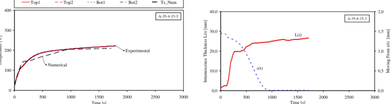
steel and virgin energy equations. When the front reaches the pyrolysis temperature, equal to 250 [ºc], starts to decompose and to move. Then the moving front rate is determined and the intumescence forms. The position the free boundary is set equal to the experimental results and the intumescence temperature field is determined. In each time step the virgin and char layers are remeshed.
0 100 200 300 400
0 500 1000 1500 2000 2500 3000
Time [s] T em p e ra tu re [ ºC ]
Top1 Top2 Bot1 Bot2 Ts_Num
A-35-4-15-3 Experimental Numerical 0,0 10,0 20,0 30,0 40,0
0 500 1000 1500 2000 2500 3000
Time [s] In tu m es ce n c e T h ic k n e ss L (t ) [m m ] 0,0 0,5 1,0 1,5 2,0 M o v in g F ro n t s( t) [m m ] A-35-4-15-3 L(t) s(t)
Fig. 11. Comparison of measured and computed steel temperatures and position of the moving front, 1
125 0 = KJmol−
E .
that defines the amount of mass loss of virgin paint. The value used in the simulations was obtained from the literature, but the correct values of both paints are needed. Currently a set of thermogravimetric tests are being conducted to determine reaction kinetics parameters, the activation energy and the exponential factor.
4
Conclusions
A numerical model is applied to determine the steel temperature considering the intumescence measured in the cone calorimeter experimental tests. The model considers the intumescent heat sink and swelling based in the mass transfer, swelling and the kinetic decomposition. The results show that temperature variation is strongly dependent on the kinetic parameters.
Acknowledgments
The authors acknowledge financial support from the Portuguese Science and Technology Foundation, project PTDC/EME-PME/64913/2006, “Assessment of Intumescent Paint Behaviour for Passive Protection of Structural Elements Submitted to Fire Conditions”, and fellowship SFRH/BD/28909/2006. The authors also acknowledge the contribution from the paints producers: CIN and Nullifire.
References
1. Mesquita, L.M.R.; Piloto, P.A.G.; Vaz, M.A.P.; Pinto, T.; “Decomposition of intumescent coatings:
comparison between numerical method and experimental results”, Application of Structural Fire Design, ISBN: 978-80-01-04266-3, pp. 140-145, Prague, Czech Republic, 19-20 February 2009.
2. ISO 5660-1:2002, Reaction-to-fire tests - Heat release, smoke production and mass loss rate. Part 1: Heat
release rate (cone calorimeter method), International Organization for Standardization, 2002.
3. C. Lautenberger, A Generalized Pyrolysis Model for Combustible Solids, Ph.D . thesis, University of
California at Berkeley, Berkeley, CA, 2007.
4. Koo, J. H., “Thermal characterization of a ceramic intumescent material”, Fire Technology, Vol. 34, Nº 1,
1998.
5. Anderson, C.E.; Ketchum, D.E., Mountain, W.P. “Thermal Conductivity of Intumescent Chars”, Journal of
Fire Sciences, vol. 6, pp. 390, 1988.
6. M. Bartholmai, R. Schriever, B. Schartel, “Influence of external heat flux and coating thickness on the
thermal insulation properties of two different intumescent coatings using cone calorimeter and numerical analysis”, Fire and Materials, Vol. 27, Issue 4, 151 – 162, 2003.
7. Wouwer A.V, Saucez P., and W. E. Schiesser, “Simulation of Distributed Parameter Systems Using a
![Fig. 2. Steel plate temperatures for 4 [mm] specimens, with coating B, tested with heat a flux of 35 [kwm -2 ]](https://thumb-eu.123doks.com/thumbv2/123dok_br/16983703.763117/3.892.108.441.117.299/fig-steel-plate-temperatures-specimens-coating-tested-heat.webp)