JSCS–4262 Original scientific paper
On the kinetics of the hydrogen evolution reaction on
Ni–MoO
xcomposite catalysts in alkaline solutions
BORKA M. JOVIĆ1, UROŠ Č. LAČNJEVAC1#, VLADIMIR D. JOVIĆ1, LJILJANA M.
GAJIĆ-KRSTAJIĆ2# and NEDELJKO V. KRSTAJIĆ3
1Institute for Multidisciplinary Research, University of Belgrade, P. O. Box 33, 11030 Belgrade, Serbia, 2Institute of Technical Sciences SASA, Knez Mihajlova 35, 11000 Belgrade, Serbia and 3Faculty of Technology and Metallurgy, University of Belgrade,
Karnegijeva 4, 11000 Belgrade, Serbia (Received 21 June, revised 19 September 2011)
Abstract: MoO3 particles were co-deposited with Ni onto smooth or rough Ni
supports from modified Watt baths of different compositions. Morphology and composition of the electrodeposits were characterized by means of cyclic vol-tammetry, X-ray diffraction analysis, scanning electron microscopy, transmis-sion electron microscopy and energy dispersive X-ray spectroscopy. The elec-trocatalytic activity of the composite catalysts for H2 evolution in alkaline so-lutions was determined by quasi-stationary polarization curves. Activity in-creases with MoOx content in the Ni deposit up to a limiting value. The com-posite Ni–MoOx catalysts exhibited high catalytic activity, similar to that of a
commercial Ni–RuO2 catalyst. Stability tests showed that the Ni–MoOx co-deposits were stable under constant current conditions and exhibited excellent tolerance to repeated short-circuiting.
Keywords: hydrogen evolution; nickel; molybdenum trioxide; composite cata-lyst; co-deposition.
INTRODUCTION
The hydrogen evolution reaction (HER) is one of the most studied electro-chemical reactions because it occurs through a limited number of reaction steps with only one reaction intermediate involved. It is a unique electrochemical reac-tion for which the complete theory of electrocatalysis was developed.1,2
Hydrogen evolution is the most frequent cathodic reaction in industrial elec-trolytic processes and has been recognized as a valuable fuel that may well re-place oil as an energy source. It also plays a major role in synthetic organic che-mistry in the well-known catalytic hydrogenation process.3 One major aspect of
the research undertaken is to improve catalytic electrode materials in terms of their activity, efficiency and mechanical and corrosion stability. Nickel-based materials were shown to exhibit these characteristics and are widely used in in-dustrial processes.
Alloying two metals has long appeared to be the most straightforward way of achieving electrocatalytic activation. In the case of the hydrogen evolution re-action, it seems that Ni–Mo catalysts, either electrodeposited,4 or thermally
pre-pared,5 or added in situ,6 have constituted the main objective of research during
the past twenty years.
Synergetic effects were explicitly ruled out in the case of in situ activation with molybdate.7,8 As molybdate was deposited from technical solutions, a co-
-deposit of Mo and Ni (Fe, Co) was in fact formed, but the Tafel slope remained the same as that for pure Ni. The same was the case of Ni–Mo bulk alloys.9 In
the case of Ni–Mo catalysts prepared by thermal decomposition of suitable pre-cursors, synergetic effects were observed, with a maximum at around 30 at. % Ni.10 The Tafel slope decreased to 40 mV and extended to very high current
densities, while the exchange current density close to 10 mA cm–2 was by three
orders of magnitude higher than that for bulk Ni. However, these electrodes did not possess the expected stability during prolonged electrolysis, mainly due to the drastic irreversible reduction of the corresponding metal oxides during cathodic polarization, which caused the collapse of the oxide lattice.11
Ni–Mo coatings obtained by electroplating exhibited so-called “synergetic effects” in contrast to Ni–Mo bulk alloys.12,13 The specific role of Mo in Ni–Mo
electroplated coatings could be explained by the fact that the molybdenum was present more likely as an amorphous oxides phase than as a pure metallic phase. However, the morphology of Ni (Fe,Co)–Mo electroplated coatings were charac-terized by the presence of numerous micro-cracks down to the support.14–18
Ac-cumulation of molecular hydrogen in localized areas, such as micro-cracks, in the coating may result in the formation of internal bursts or blisters and the coating becomes mechanically fragile. In addition, it was found that Mo is not at all stable in alkaline solution when a cell is shut down, as it tends to be leached out, which could be the origin of deactivation on cathodic load.19
Improved performances are to be expected if a composite compact layer of Ni and some Mo oxides could be prepared by the simultaneous electrodeposition of Ni and MoO3 from an electrolyte solution in which MoO3 particles are
sus-pended. It seems a unique way for solving the problem of porosity of electro-plated Ni–Mo coatings and low mechanical stability of thermally prepared Ni–Mo catalysts. Therefore, the aim of this study was to determine the conditions for the preparation of compact Ni–MoOx composite coatings possessing high catalytic
EXPERIMENTAL Electrode preparation
The Ni/(Ni–MoOx) active cathodes were prepared by the simultaneous electrodeposition
of Ni and suspended MoO3 particles onto a Ni substrate from a Watt bath of the following
composition: NiSO4⋅6H2O – 330 g dm-3; NiCl2⋅6H2O – 45 g dm-3; H3BO3 – 38 g dm-3; pH:
3.2–4.0. The deposition was performed at 40 °C. Nickel platelets (10 mm×10 mm×0.2 mm) with a very thin stem were used as substrates.
The MoO3 powder was prepared by thermal decomposition of (NH4)6Mo7O24⋅4H2O at
500 °C for 2 h under an air atmosphere20 and was dispersed by means of a magnetic stirrer.
The amount of MoO3 particles in the bath was varied between 0 and 20 g dm-3.
The pre-treatment of the Ni support consisted of either etching (HCl) or mechanical po-lishing (emery paper). Electrodeposition was performed galvanostatically in a stirred solution (magnetic stirrer at 400 rpm) at 40 °C by varying the current density, typically from 5 to 50 mA cm-2, for a constant electricity (72 C cm-2). All deposition experiments were performed
using a self-made rectifier. Electrode characterization
Scanning electron microscopy (SEM, on JOEL 840) was used to characterize the mor-phology of the as-deposited surface. Transmission electron microscopy (TEM) measurements were performed using the FEI (Fillips Electronic Instruments) – CM200 super-twin and CM300 ultra-twin microscopes operating at 200 and 300 kV, equipped with Gatan 1k×1k and
2k×2k CCD cameras, respectively. Specimens for TEM analysis were prepared by making a
suspension of the catalyst powder in ethanol, using an ultrasonic bath. The catalyst powder was prepared by grounding the Ni–MoOx coating electrodeposited onto a glassy carbon support.
XRD Analysis of Ni–MoO3 composite coatings was carried out by Siemens D-500
diffracto-meter. CuK radiation was used in conjunction with a CuK (nickel filter). Obtained X-ray dif-fraction pattern was used to evaluate the phase structure and crystallite size of the coatings. Cell and chemicals
A conventional three-compartment cell was used. The working electrode (WE) ment was separated by fritted glass discs from the other two compartments. The WE compart-ment was jacketed and thermostated during measurecompart-ments at 25.0 °C or at 85 °C, using a thermostat. All measurements were performed in 1.0 mol dm-3 or 33 wt. % NaOH solution (Spectrograde, Merck), prepared in deionized water. The WE compartment was saturated with purified hydrogen at standard pressure during measurements. A saturated calomel electrode (SCE) or a reversible hydrogen electrode (RHE) in the same solution were used as the refe-rence electrodes while a flat Pt sheet served as the counter electrode.
Electrochemical measurements
Tafel lines were recorded using potentiostatic steady-state voltammetry, point by point at 60 s intervals, using a PAR 273 potentiostat, with good reproducibility of measurement. Whenever the potential of the WE approached approximately –1.3 V (SCE) (or when current densities were close to, above approximately 0.1 A cm-2) it was found that the uncompensated
RESULTS AND DISCUSSION Efficiency of electrodeposition
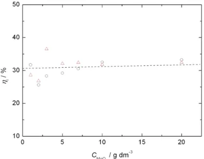
The variation of the current efficiency for Ni electrodeposition as a function of the concentration of MoO3 particles in the solution at a constant current
den-sity of 10 mA cm–2 is shown in Fig. 1. The current efficiency was estimated from
deposition charge and weight increase measurements, assuming that the latter was due to Ni only, without correction for the contribution to the overall weight increase of the dispersed phase. As can be seen from Fig. 1, the current efficiency did not depend significantly on the concentration of suspended MoO3 particles in the range from 1 to 20 g dm–3. The current efficiency for Ni electrodeposition
was generally very low, indicating a high catalytic activity of the Ni–MoOx
co-de-posits for the HER, which occurred as a parallel reaction during electrodepo-sition. However, it is important to emphasize that partial reduction of MoO3 can also takes place during electrodeposition, according to the following overall reac-tions:
3 3
MO +xH++xeH MoOx (1)
or
3 3 2
MO +2 Hy + +2yeMoO −y+ H O (0< <1)y y (2) Reaction (1) or (2) could additionally reduce the current efficiency for Ni
electrodeposition.
This speculation is based on previous experiments that showed the reduction of MoO3 powder in a hydrogen atmosphere at temperature of 623 K proceeded via the formation of hydrogen molybdenum bronze, HxMoO3. Therefore, during
Ni+MoO3 co-deposition, the formation of similar reduced phases of MoO3 could occur in which hydrogen species adsorbed onto the Ni surface participate in this reaction.
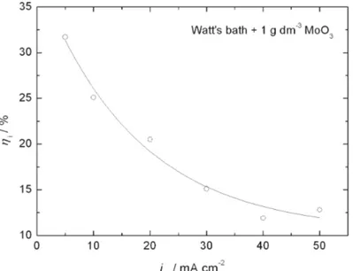
The dependence of the current efficiency on the applied current density of deposition at a constant concentration of suspended MoO3 particles in the bath (1 g dm–3) is shown in Fig. 2. The current efficiency decreases with increasing
ap-plied current density, probably due to the increase in the relative deposition rate of Ni to MoO3 particles, which leads to an increase of the catalytic activity of
composite (Ni–MoOx) coatings for the HER.
Fig. 2. Current efficiency for Ni+MoO3 co-deposition as a function of the applied current,
determined in a Watt bath containing 1 g dm-3 of MoO
3 particles.
Morphology and chemical composition of composite the Ni–MoOx electrodeposits
Typical top views of the Ni–MoOx composites electrodeposited at different
current densities from a Watt bath containing 1 g dm–3 of suspended particles
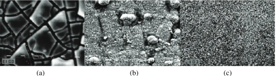
MoO3. As can be seen, the morphology of the Ni–MoOx coating deposited at a
lower current density is characterized by the presence of micro-cracks, with some 2 µm in width (Fig. 3a), and a high concentration of MoO3 particles. However,
The X-ray diffraction (XRD) pattern for a Ni–MoOx electrodeposit is shown
in Fig. 4. It was found that the XRD peaks of MoO3 had disappeared after co-de-position with Ni and that the Ni–MoOx composite coating was completely
amor-phous in nature. The reason for the disappearance of the corresponding XRD peaks is not clear at this stage; the change to an amorphous MoOx phase during
the co-deposition is probably the result of a reduction process in which Hads spe-cies participate. Thus, due to amorphous nature of the coating, it was necessary to characterize the composite coating by energy dispersive X-ray spectroscopy (EDS) to determine the chemical composition of the Ni–MoOx coatings.
(a) (b) (c) Fig. 3. Scanning electron micrographs of the Ni–MoOx electrode surfaces electrodeposited at:
a) jNi = 10 mA cm-2; b) j
Ni = 20 mA cm-2; c) jNi = 50 mA cm-2. The concentration of MoO3
particles in the Watt bath was 1 g dm-3. Magnification 1000×.
Fig. 4. XRD Pattern (2Θ in degrees) of the composite (Ni–MoOx) coating prepared by
electro-deposition from a Watt bath containing 1 g dm-3 of MoO
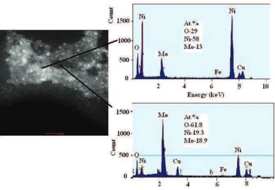
MoOx particles (white spots) were relatively uniformly distributed in Ni matrices
(Fig. 5). The chemical composition of the coating (sample obtained by electrode-position at 30 mA cm–2) at different positions (EDS spectra) is presented in Fig. 5.
Fig. 5. TEM dark field image and EDS spectra of an electrodeposited Ni–MoOx layer
(jNi = 50 mA cm-2; 1 g dm-3 MoO3) on a smooth Ni support from a Watt bath.
The MoOx particles are presented by white spots and the corresponding
EDS spectra of the region with a low and a high content of Mo oxides.
The average content of Mo oxides in the composite coating generally de-creased with increasing deposition current density.
Cyclic voltammetry in 1.0 mol dm–3 NaOH
The electrode surfaces of the Ni–MoOx catalysts were characterized by
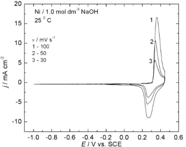
means of their voltammetric curves (VC). A series of VCs recorded at different scan rates is shown in Fig. 6. The corresponding curves of Ni in the same solu-tion are shown in Fig. 7, for comparison. Reproducible and characteristic voltam-mograms were obtained. Both electrodes are characterized by a highly reversible peak prior to the oxygen evolution reaction. The reactions occurring at potentials in the range of both the anodic current and the cathodic current peaks are appa-rently complementary processes, which are represented by the overall reaction:
Fig. 6. Cyclic voltammetric curves over the potential range of –1.0 to 0.45 V (SCE) of a Ni/(Ni–MoO–) composite electrode (prepared by electroplating at 50 mA cm-2 in a
Watt bath containing 1 g dm-3 of MoO
3 particles) in 1.0 mol dm–3 NaOH solution at 25 °C.
Fig. 7. Cyclic voltammetric curves over the potential range –1.0 to 0.45 V (SCE) of a Ni electrode in 1.0 mol dm-3 NaOH solution.
positive value (≈ 50 mV). Consistently, O2 evolution commenced at a ca. 50 mV more negative potential on the Ni electrode than on the composite. The increase of both the anodic and cathodic peaks could be explained by the surface of Ni– –MoOx being rougher than that of the etched Ni surface, because the
participa-tion of Mo oxides redox reacparticipa-tions could not be expected, according to the ther-modynamic data. Anodic peak current density of the Ni–MoOx composite
cata-lyst was around two times higher, which means that the real surface area of this electrode is approximately two times higher than the real surface area of the etched Ni electrode.
Polarization measurements in 1.0 mol dm–3 NaOH
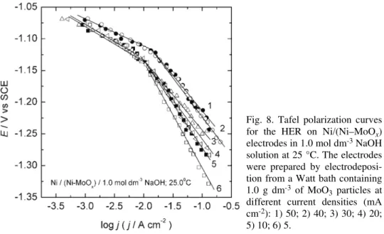
The polarization curves for the HER obtained on different Ni/(Ni–MoOx)
electrodes prepared by co-deposition onto a mechanically polished Ni substrate, from 1.0 mol dm–3 NaOH solution are shown in Fig. 8. The polarization curves
were recorded after holding the electrodes at a constant cathodic current density of 100 mA cm−2for about 1 h. The polarization curves are characterized by two
Tafel slopes at all electrodes, b1≈–40 mV in the lower overpotential region and b2≈–120 mV in the high overpotential region. The composite Ni–MoOx coating
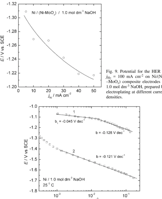
obtained by electroplating at jNi = 50 mA cm–2 was found to have the lowest
hydrogen overpotential (Fig. 9) and the highest exchange current density, j0 ≈ ≈ 7.9×10⁻⁴ A cm−2 (Fig. 8). The corresponding kinetic parameters for the HER
for these electrodes are presented in Table I.
Fig. 8. Tafel polarization curves for the HER on Ni/(Ni–MoOx)
electrodes in 1.0 mol dm-3 NaOH
solution at 25 °C. The electrodes were prepared by electrodeposi-tion from a Watt bath containing 1.0 g dm-3 of MoO
3 particles at
different current densities (mA cm-2): 1) 50; 2) 40; 3) 30; 4) 20;
5) 10; 6) 5.
/(Ni–MoOx), only one Tafel slope of about –120 mV dec–1 is present over the
complete potential range for the HER on Ni. At the same potential, the activity of Ni/(Ni–MoOx) was about four orders of magnitude higher than that of the Ni
electrode. It is clear from the morphological investigations that the incorporation of MoO3 particles into a Ni deposit produces roughness, but undoubtedly, syner-
Fig. 9. Potential for the HER at jH2 = 100 mA cm-2 on Ni/(Ni–
–MoOx) composite electrodes in
1.0 mol dm-3 NaOH, prepared by
electroplating at different current densities.
Fig. 10. Tafel polarization curves for the HER on the most active Ni/(Ni–MoOx) electrode
getic effects are achieved, because the Tafel slope decreases to –40 mV in the lower overpotential region and extends to relatively high current densities. It was shown21 that the reaction mechanism of the HER on Ni is a consecutive
com-bination of a Volmer and a Heyrovsky step, and that the Heyrovsky step prevails over the Tafel step in the low overpotential region and that the reaction rate is controlled by the Heyrovsky reaction with an almost full coverage by Hads. How-ever, the presence of Tafel slope of –40 mV for the HER on the Ni/(Ni–MoOx)
electrode indicates that the Heyrovsky step controls the rate of the overall reac-tion in the lower potential range, but with a low coverage by Hads intermediates.
In accordance with the mechanism of the HER, both the Volmer and the Hey-rovsky steps occurred at a single adsorption site and the reaction occurred at the Ni electrode with an almost full coverage by Hads, but with a low coverage by Hads in the case of the Ni/(Ni–MoOx) electrode. The fact that the reaction rate
was almost four orders of magnitude higher on the latter electrode, indicates an increased catalytic activity of the adsorption sites for the HER on the Ni/(Ni– –MoOx) electrode.
Electrochemical characteristics of the composite Ni–MoOx catalyst in 33 wt.% NaOH solution
The polarization characteristics of the most active Ni/(Ni–MoOx) cathode
were tested in a 33 wt. % NaOH solution at 85 °C, which are typical conditions for industrial chlor–alkali electrolysis.
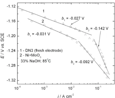
The polarization curve for the HER at the Ni/(Ni–MoOx) electrode is shown
in Fig. 11. The polarization curve for the HER at a commercial DN3 electrode (Ni–RuO2, DeNora cathode) is also presented in the same figure, for comparison. It is interesting to note that both electrodes possessed practically the same acti-vity for HER at j = –0.3 A cm–2.
In industrial chlor–alkali electrolysis, one of the technical methods for replacing some the electrodes by new ones is the short-circuiting of a cathode and an anode in the electrolysis bath. Then a reverse current flows through a bypass circuit and the cathode is oxidized, resulting in the loss of electrocatalytic activity for the HER. In the case of the Raney-Ni active cathode, the potential was sharply shifted in the positive potential direction immediately after the short-circuiting and reached 0.30 V vs. SCE within about 3 min. It was reported by Yoshida and Morimoto22 that the reverse current on short-circuiting caused a shift of the
po-tential toward oxidation of the Raney-Ni electrode to lower its electrocatalytic activity, due to formation of NiOOH surface oxide. In order to simulate short-cir-cuiting condition, Ni/Ni–MoOx cathode was repeatedly polarized at 0.30 V (SCE)
for 1000 s, and polarization curves for the HER were recorded after short-cir-cuiting (Fig. 12). At an applied current density of 300 mA cm–2, a decrease of the
that the Ni/(Ni–MoOx) active cathode kept an excellent activity irrespective of
the presence and the absence of a reverse current due to short-circuiting.
Fig. 11. Tafel polarization curves for the HER on a commercial DN3 electrode (1) and Ni/(Ni–MoOx) electrode (2) in 33 wt. % NaOH solution at 85 °C.
The composite electrode was prepared by electrodeposition from a Watt bath containing 1 g dm-3 of MoO
3 particles at jNi = 50 mA cm-2.
Fig. 12. Tafel polarization cur-ves for the HER on a Ni/(Ni– –MoOx) electrode in 33 wt. % NaOH solution at 85 °C, re-corded after short-circuiting. The composite electrode was prepa-red by electrodeposition from a Watt bath containing 1.0 g dm-3
CONCLUSIONS
Co-deposition of Ni and MoO3 particles from a Watt bath produced compo-site catalysts that possessed high activity for the HER in strong alkaline solutions.
During co-deposition, partial reduction of the MoO3 particles occurred and the Ni–MoOx composite coatings prepared by deposition at lower current
densi-ties were completely amorphous in nature.
The maximum activity was obtained already at 1 g dm–3 MoO3 in solution
(suspension).
Co-deposition resulted in increased surface roughness. The roughness factor for the Ni–MoOx composite electrode was two orders of magnitude higher than
that of a polished Ni electrode.
The true catalytic activities of the composite Ni–NiOx catalysts for the HER
were about two orders of magnitude higher than that of an etched Ni electrode. The Ni–MoOx composite catalyst possessed the same activity at high current
density for the HER as a commercial DeNora (DN3) electrode in 33 wt. % NaOH solution at 85 °C.
Preliminary stability tests showed that anodic pretreatment of the composite catalyst that simulated short-circuiting conditions did not deactivate the electrode for the HER.
Acknowledgment. This work is financially supported by the Ministry of Education and Science of the Republic of Serbia, under contract No. 172054.
NI–MoOx
. 1, . 1, . 1,
. - 2 . 3
1Institut za multidisciplinarna istra`ivawa, Univerzitet u Beogradu, 11030 Beograd, 2Institut
tehni~kih nauka SANU, Knez Mihajlova 35, 11000 Beograd i 3Tehnolo{ko
–metalur{ki fakultet, Univerzitet u Beogradu, Karnegijeva 4, 11000 Beograd
Ni–MoOx MoO3
Watt- .
,
X- .
-ђ .
3 Ni ђ . Ni–MoOx
,
Ni–RuO2 (De Nora) . Ni–MoOx
REFERENCES 1. R. Parsons, Trans. Faraday Soc. 54 (1958) 1053
2. S. Trasatti, J. Electroanal. Chem. 39 (1972) 163
3. R. L. Augustine, in Catalytic Hydrogenation, Marcel Dekker, New York, 1985, p. 26 4. N. Elezović V. D. Jović, N. V. Krstajić, Electrochim. Acta50 (2008) 5594
5. D. E. Brown, M. N. Mahmood, A. K. Turner, S. M. Hall, P. O. Fogarty, Int. J. Hydrogen Energy7 (1982) 405
6. J. Y. Huot, L. Brossard, J. Appl. Electrochem.18 (1988) 815
7. J. Y. Huot, L. Brossard, J. Appl. Electrochem. 20 (1990) 281
8. J. Y. Huot, L. Brossard, Surf. Coat. Technol. 34 (1998) 373
9. B. E. Conway, L. Bai, J. Chem. Soc., Faraday Trans. 181 (1985) 1841
10. M. M. Jakšić, Mat. Chem. Phys. 1 (1989) 22
11. M. Yoshida, Y. Noaki, in Performance of Electrodes for Industrial Electrochemical Processes, F. Hine, B. V. Tilak, J. M. Fenton, J. D. Lisius, Eds., The Electrochemical Society, Penington, NJ, USA, 1989, p. 15
12. L. S. Sanches, S. H. Domingues, A. Carubelli, L. H. Mascaro, J. Braz. Chem. Soc. 14
(2003) 556
13. L. S. Sanches, S. H. Domingues, C. B. Marino, L. H. Mascaro, Electrochem. Commun. 6
(2004) 543.
14. E. J. Podlaha, D. Landolt, J. Electrochem. Soc. 143 (1996) 893
15. E. Chassaing, N. Portail, A. F. Levy, G. Wang, J. Appl. Electrochem., 34 (2004)1085.
16. M. Donten, H. Cesiulis, Z. Stojek, Electrochim. Acta50 (2005) 1405
17. M. Donten, H. Cesiulis, Z. Stojek, Electrochim. Acta45 (2000) 3389
18. H. Cesiulis, A. Baltutiene, M. Donten, M. L. Donten, Z. Stojek, J. Solid State Electrochem.6 (2002) 237
19. J. Divisek, H. Schmitz, J. Balej, J. Appl. Electrochem. 19 (1989) 519
20. Z. M. Hanafa, M. A. Khilla, M. H. Askae, Thermochim. Acta45 (1981) 221
21. N. Krstajić, M. Popović, B. Grgur, M. Vojnović, D. Šepa, J. Electroanal. Chem. 512
(2001) 16