Evaluation of Calcined Hydrocalumite-type Materials as Supports
of CoMo and NiMo for Thiophene Hydrodesulfuration Reaction
Carlos Felipe Linaresa* Pablo Brettoa, Ruth Álvareza, Freddy Ocantoa,
Carolina Coraoa, Paulino Betancourtb, Joaquín Luis Britoc
aDepartamento de Química, Facultad de Ciencias y Tecnología, Unidad de Síntesis de Materiales y
Metales de Transición, Universidad de Carabobo, Valencia. Edo. Carabobo, Venezuela
bLaboratorio de Tratamiento Catalítico de Efluentes, Centro de Catálisis, Petróleo y Petroquímica,
Universidad Central de Venezuela. Caracas, Venezuela
cLaboratorio de Fisicoquímica de Superficies, Centro de Química, Instituto Venezolano de
Investigaciones Científicas, IVIC. Apartado 20632, Caracas 1020-A, Venezuela
Received: August 28, 2013; Revised: January 28, 2014
A hydrocalumite-type material (HC) was synthesized by the co-precipitation method, mixing Ca and Al nitrate solutions in a NaOH solution (pH ≅ 11). This solid was characterized by using
different physico-chemical techniques such as: Fourier-transform infrared spectroscopy (FT-IR), X-ray diffraction (XRD), temperature programmed reduction (TPR) and BET surface area measurements. Then, a portion of as-synthesized solid was calcined at 420 ºC (HC 420). Both calcined and pristine solids were impregnated with Mo (15% w/w as MoO3). Ni or Co was also impregnated on Mo/HC or Mo/HC 420 in 1(Co or Ni):3 (Mo) atomic ratios to get catalytic precursors. These solids were also characterized by the above mentioned techniques. Catalytic precursors were tested in the thiophene hydrodesulfuration reaction at 280 ºC and atmospheric pressure. Cobalt promoted catalysts were more active than those promoted with Ni. However, thiophene conversions were lower than that of a conventional CoMo/γ-Al2O3 catalyst.
Keywords: hydrocalumite, hydrotreatment, thiophene, CoMo, NiMo
1. Introduction
Hydrotreatment (HDT) is often used for reducing heteroatoms and aromatics contents from fossil fuels. Therefore, HDT catalysts play a very important role, both in refining technology and for environment protection. Effectiveness of these catalysts minimizes costs of production of clean combustibles1,2.
New legislations have been advanced in order to impose minimum sulfur contents in fossil fuels. A possibility to produce better catalysts is the use of new supports which should render more active and cheaper catalysts than those currently employed3.
In this way, hydrotalcite-type materials, whose structure is similar to hydrocalumite-types, have been studied as HDT catalyst supports, especially, those synthesized with Al and Mg4,5; however, Ca-Al hydrocalumite-type solids have
not been documented for this purpose. Hydrotalcites and hydrocalumite are two minerals closely related, belonging to the layered double hydroxide family. Both structures are based on positive brucite-like layers alternating with layers containing anions and water molecules. Hydrotalcites-like materials are far more common, while hydrocalumite structure type is rare and less broad in composition4,5.
Vieille et al.6, studied the phases obtained upon
dehydration and decomposition of hydrocalumites by using
different techniques such as in situ (high temperature) XRD and TGA. TGA analysis showed that this type of solid undergoes to three-step decomposition on heating: dehydration, dehydroxylation, and anion expulsion, respectively, over the following temperature ranges: 25-250, 250-400, and >400 °C. Sharp phase transitions were observed as a result of the ordered distribution of Ca and Al atoms in the hydroxide layer and the well-ordered interlayer structure.
On the other hand, López-Salinas et al.7, studied
hydrocalumites in the isomerization reaction of 1-butene. This solid was characterized by XRD, surface area and pore size and CO2 TPD. The layered structure of HC collapses above 250°C yielding an amorphous material at 323°C, which upon calcination at 600-700°C transforms into a mixture of CaO and mayenite (calcium aluminium oxide of cubic symmetry, Ca12Al14O33). The calcination temperature has a marked effect in the formation of basic sites. Thus for example, HC calcined at 800°C shows 90% of strong basic sites while they are absent in HC calcined at 600-700°C.
This paper explores the hydrocalumite as support of CoMo or NiMo oxides for use in the HDS reaction of thiophene. Results were compared to a commercial CoMo/ alumina catalyst.
2. Experimental
2.1.
Synthesis of Hydrocalumite (HC)
Hydrocalumite was synthesized by the co-precipitation method previously reported by López-Salinas et al7. A Ca/Al
solution was prepared dissolving Al(NO3)3·9H2O (11.90 g) and Ca(NO3)2·4H2O (14.90g) in distilled water. This solution was added dropwise to 25 mL of a NaOH solution (25 g), and kept under stirring in an inert atmosphere. The resultant mixture was refluxed by using a glycerin bath at 80 °C for 12 h under constant agitation, inert atmosphere and pH≅11. Then, a white solid was filtered from the mixture, washed up with abundant distilled water and dried at 100°C for 18 h.
The solid was divided in two portions. One of them (identified as HC 420) was calcined by using a muffle at 420°C for 4h by using a heating ramp of 5°C/min from room temperature. Another portion (HC) was not calcined.
2.2.
Impregnation of hydrocalumite.
Both portions of hydrocalumite, before and after calcination, were impregnated with Mo as active phase, and Co and Ni as promoters. The impregnation was carried out by using the incipient wetness method. Mo was impregnated from an ammonium heptamolybdate solution, its content was 15% w/w as MoO3;Co or Ni were impregnated from the nitrate salts in a 1:3 Co(Ni):Mo atomic ratio. Impregnated solids were dried at room temperature for 24 h, and calcined up to 420°C for 4 h by using a heating rate of 5 °C/min.
2.3.
Characterization of solids
As-synthesized hydrocalumite and catalytic precursors were characterized by powder X-ray diffraction (Phillips PW3710 CuK(α): 1,542). Fourier-transform infrared
spectroscopy (FT-IR) (Shimadzu 8400s FT-IR) by using KBr as pellet forming agent. Spectra were recorded between 4000-500 cm–1. BET surface area measurements were
carried out by using a Micromeritics ASAP 2010 instrument and N2 gas as adsorbent molecule at a temperature –196°C by using a 90/10 v/v ratio He/N2. Approximately, 50-100 mg samples were placed in a tube and heated to 250°C for degassed under vacuum for 4 h. After outgassing, samples were weighed to determine the actual sample weight. Temperature programmed reduction (TPR), were carried out in a Chemisorb Analizer 2900 from Micromeritics. The samples were heated up to 1000°C under flowing H2/ Ar (10/90 v/v). A heating rate of 10°C/min and 20 mg of samples were used during TPR experiments.
2.4.
Catalytic activity
Co(Ni)/hydrocalumite catalytic precursors were tested in thiophene HDS reaction, and compared to a commercial CoMo/γ-Al2O3 catalyst (HR-306, 195 m2/g). Thiophene
HDS was carried out in a continuous flow reactor working at atmospheric pressure. All catalysts were presulfided prior to catalytic tests using a CS2 (10 v/v %, 10 mL.h–1)/heptane
solution under H2 stream (100 mL.min–1) and kept at these
conditions at 400°C for 3 h. Samples were heated from room temperature until 400° by using a heating rate of 10°C/min. Then, the reaction took place on 200 mg samples of catalyst
using a liquid feed (2.7 10-4 cm3 s–1) composed of 10 p/p % of
thiophene in n-heptane mixed with a H2 stream (0.25 cm3 s–1)
at 280 °C. The inlet lines were covered with a heating mantle (150 °C) in order to avoid any condensation of the reactants and reaction products. Reaction products and unreacted feed were analyzed with a Varian 3800 (AutoSystem XL) gas chromatograph equipped with a flame ionization detector.
3. Results and Discusion
3.1.
Characterization of hydrocalumite
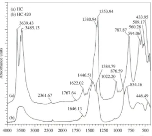
Hydrocalumite (HC) was characterized by FT-IR (Figure 1). According to Kok et al.8, NO
3– ion exhibits three
characteristic bands: υ1 in ~ 1380 cm–1, υ
2 in ~ 830 cm–1
and υ3 in 720-750 cm–1 range, the last two bands showing
low intensity. Indeed, a band at 1381 cm–1 can be observed
but υ2 and υ3 vibrational modes were not detected due to
their low intensity.
Bands at 3500-3700 cm–1 were attributed to OH– groups.
Bands at 3639 and 3485 cm–1 can be associated to surface
OH– groups of Ca(OH)
2 present in the hydrocalumite-type
material9. The wide band in 3500-3600 cm–1 can be also
associated OH- groups and/or to the ν(OH) mode ascribed
to interlayer water molecules located in the hydrocalumite interlaminar region10. A band at 1622 cm–1 confirmed the
water presence; while the band at 1022 cm–1 has been
assigned to OH– groups of Ca(OH)
2, this band is more
pronounced when it is determined by Raman spectroscopy9.
Between 788-509 cm–1, Al-O vibrations of the
hydrocalumite structure were observed. A band at 1354 cm–1
is characteristic of O-C-O vibrations of CO32– anions
adsorbed on the hydrocalumite11.
When the hydrocalumite is calcined (HT 420), the FT-IR spectrum is changed. Bands at: 3639, 3485 and 1022 cm–1
corresponding toOH- groups from Ca(OH)
2 and observed
in HC, disappeared during the calcination procedure (HC 420). This is product of dehydration of hydrocalumite9.
On the other hand, a wide band placed between 3500 and 3600 cm–1 and a low band at 1646 cm–1 observed in
HC 420 correspond to water molecules physisorbed on the HC 420 surface.
A broad band placed around 1446 cm–1 is due to
carbonate species which should be different from those existing in hydrocalumite9. These carbonate species could
be associated to formation of surface CaCO3 due to exposure to an air atmosphere (atmospheric CO2 and humidity) and basicity of solid11. A main band at 834 cm–1, absent in
the spectrum of hydrocalumite, and a broad band around 550 cm–1, are due to the major changes originated by the
phase transformations during the calcination process. They are due to metal-oxygen bonds9.
By examining the results of Vieille et al.6,
López-Salinas et al.7 and Campos-Molina et al.12, it can
be concluded that the transformation of hydrocalumite during the calcination occurs in three steps: in the first one (25-200°C), the physisorbed water is lost from the hydrocalumite structure. The second (200-400°C) and third steps (400-800°C) correspond to dehydroxylation and expulsion of anions. An exact sequence has not been established, however, it was reported that the material still losses water from dehydroxilation at temperatures above 600°C12. This could explain water molecule bands of the
material observed on HC 420 (Figure 1b).
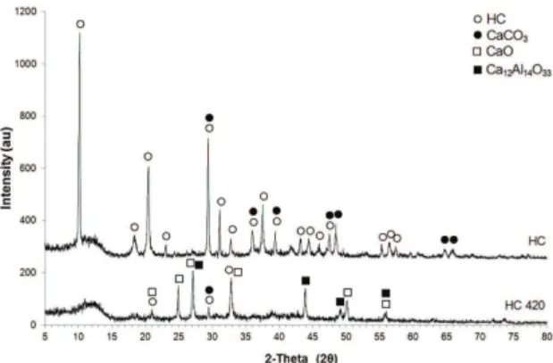
A clear identification of hydrocalumite phases was done by using XRD. Figure 2 shows the XRD pattern of HC and HC 420.
Characteristic intense peaks at 10, 20 and 29 degrees (2θ), and also other less intense bands belonging to HC6
were found in the corresponding sample; moreover, a small amount CaCO3 phase (JCPDS: 85-1108) could be also identified. The basic conditions of synthesis of hydrocalumite, permitted the formation CaCO3 due to absorption of atmospheric CO2.
The calcination of HC produced the formation of different phases such as: CaO (JCPDS: 17-0912), Ca12Al14O33 mayenite (JCPDS: 48-1882) and CaCO3 (JCPDS: 85-1108) (Figure 2). According to López-Salinas et al.7, the calcination of HC at 500°C produces
CaO, while calcination at higher temperatures (upon 600°C) produces CaO and Ca12Al14O33.
BET surface area measurements were also carried out. One can see that for HC 420 (17 m2/g), the surface area is
diminished in 23% in comparison with that of HC (22 m2/g).
This could be associated to the higher size of crystallites. López-Salinas et al.7, showed that calcination of HC between
400-500°C produced surface areas between 34-26 m2/g, in
agreement with the lower crystallinity of their solids. Figure 3 shows the XRD patterns of CoMo/(HC or HC 420) catalytic precursors. Several oxidic phases such as MoO3 (JCPDS: 85-2405), scheelite CaMoO4 (JCPDS: 85-1267), CaO (JCPDS: 17-0912), mayenite Ca12Al14O33 (JCPDS: 48-1882) and CaCO3 (JCPDS: 85-1108) were identified.
MoO3 is produced by oxidation of the impregnated molybdenum precursor. Phases containing Co oxides were not detected for CoMo/(HC or HC 420). This result could be due to the low Co concentration or to Co oxide crystals
being amorphous. Similar results were obtained for NiMo/ (HC or HC 420). (Figure 4)
XRD patterns of CoMo and NiMo supported on HC or HC 420 were quite similar. Therefore, from this technique point of view there are not differences due to the additional calcination procedure.
Table 1 shows the BET surface areas measurements of studied catalytic precursors. An increase of BET surface area from 38 to 43 m2/g was observed when comparing CoMo/
HC with CoMo/HC 420. In similar way, for NiMo/HC 420 was observed an increase of 37 % with respect to NiMo/HC.
Figure 2. Powder XRD patterns of HC and HC 420.
Figure 3. Powder XRD patterns of CoMo catalytic precursors supported on HC and HC 420.
It could be speculated that micropores could be obtained in the supported oxide phases (see below).
Comparing the BET surface area of solids, HC and HC 420, and those reported on Table 1, we can observe that the BET surface area of HC is decreased when the support is calcined. The decrease in surface area of HC upon increasing calcination temperature (below 300°C) is opposite to the behavior of hydrotalcite13,14. According to
López-Salinas et al.7, mesopore diameter of HC is increased as the
calcination temperature increases which could decrease the BET surface area. Moreover, the expulsion of anions and water from HC and the formation of a dense phase could also decrease the BET surface area in these solids.
On the contrary, the surface area of supported oxides is increased when these are calcined. Impregnated oxides (CoMoOx and NiMoOx) or mixed phases formed with the hydrocalumite components (CaMoO4) could produce a microporous surface structure on the HC phase.
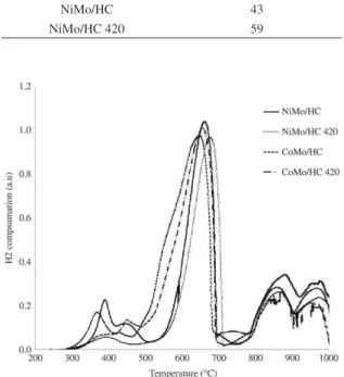
The nature of molybdenum and cobalt species on HC and HC 420 was determined from the TPR profiles. For CoMo/ HC catalyst (Figure 5) it was observed a complex pattern consisting of three peaks. The first one, of low intensity and located between 300 and 400°C, could be ascribed to partial reduction of a small amount of octahedral polymeric molybdenum species whose reducibility is increased by the promoter as compared to unpromoted polymolybdates15-17.
This TPR peak has been correlated to the catalytic activity displayed by promoted, molybdena-based catalysts16,17. An
intermediate temperature signal between 450 and 700°C
could include further reduction of the above species plus the partial reduction of additional unpromoted octahedral supported phases, and of tetrahedral Mo species from CaMoO4. It is worth mentioning that TPR peaks of alkali and alkali-earth metal molybdates appear at higher temperatures (usually above 700°C), and that they have been found to be incompletely reduced under the dynamic conditions of TPR at temperatures well in excess of 1000°C18-21. However, the
presence of Ni and Co helps in attaining higher rates (TPR peaks at lower temperatures) and extents of reduction (more intense peaks) of these phases22,23. Finally, a wide signal
between 800 and 1000°C could be a combination of the further reduction up to Mo metal of all molybdena containg phases plus that of the spinel-like phases of the promoters Co (and Ni) associated to the support. It is possible, however, that the reduction is not completed at the highest temperature of the present experiments.
Likewise, CoMo/HC 420 showed also three reduction zones (Figure 5), the main difference being that the first one corresponding to promoted octahedral polymeric molybdenum species was less pronounced than CoMo/ HC and slightly shifted to higher temperatures, suggesting decreased reducibility, which could be due to loss of the promoter from the surface by reaction with the support during calcination. The rest of reduction zones were quite similar to CoMo/HC.
Previous studies have shown that the lower temperature peaks of unsupported NiMoO422 as well as Ni promoted
Mo-based catalysts supported on alumina15, silica16 or
silica-alumina22, among other materials, appear always at
lower temperatures than the corresponding Co containing solids. Thus, it is striking that the catalysts prepared in the present study show the opposite behavior, i.e., the intensities of the first signal assigned to promoted polymolybdates are lower and the peak temperatures of the same signals are higher for Ni promoted samples (Figure 5). For the second peak there is also decreased intensity of the Ni containing catalysts at the lower temperature side of the peaks. This could be interpreted as due to Ni ions being interacting strongly with calcium oxides from the support, and thus being less available to increase the reducibility of supported polymolybdates. As in the case of the CoMo samples, the second and third peaks of the reductograms do not show significant differences between NiMo/HC and NiMo/HC 420.
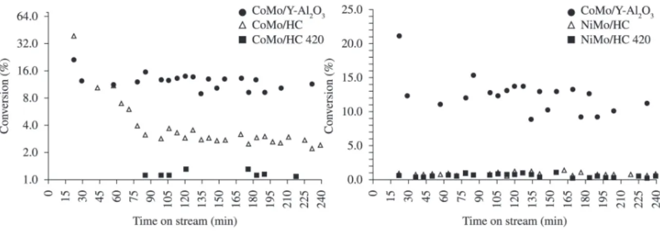
Figure 6 shows the catalytic behavior of CoMo and NiMo supported on HC or HC 420. A CoMo commercial catalyst was tested for comparison. As can be seen, the commercial catalyst was more active than CoMo and NiMo supported on HC and HC 420.
Initially (15-30 min of time on stream) the CoMo/HC conversion was 40 %. Then, this value dropped down to a 2.5 % conversion at 85 min of reaction time and kept essentially constant up to 240 min. On the other hand, CoMo/HC 420 showed a very low conversion (~0.9 %) during the full range of reaction time.
In order to better compare the activities of the samples, it was calculated the catalytic activity of catalysts determined as: converted thiophene moles/(time*surface area) (Table 2). It can be seen that the CoMo/HC catalysts
Figure 5. TPR profile of CoMo and NiMo supported on HC or HC 420.
Table 1. BET surface area of catalytic precursors.
Samples BET surface area (m2/g)
CoMo/HC 38
CoMo/HC 420 43
NiMo/HC 43
shows a higher activity than the commercial catalyst. This result demonstrates that the intrinsic activity of the active sites of the CoMo/HC supported sample are quite similar or even higher than that of sites of the commercial catalyst.
Figure 6 shows the catalytic behavior of NiMo/HC and NiMo/HC 420. Both catalysts showed a very small thiophene conversion during the whole reaction time (~0.9 % and ~0.7 % respectively). Their activity calculated in terms of the surface area (Table 2) is also lower for NiMo samples than for the CoMo ones, which again could be the result of the higher interaction of Ni promoter with the HC support as compared with Co.
Calcination effect (after and before impregnation) did not show a marked effect on the thiophene conversion for most of these catalysts, although in both cases the activity of phases supported on HC is higher than on HC-420. As the active phases of both promoted and unpromoted Mo catalysts consist of sulfides of the metals, mainly Mo, it can be assumed that the interaction with HC and the other phases observed (e.g., scheelite), render the Mo-containing phases very difficult to be sulfided, as was confirmed in TPR profiles. In particular, alkali and alkaline-earth metal molybdates have been shown to be much less reducible (and thus, probably less sulfidable) than MoO3 and/or mixed Co- and Ni-molybdates18-21. However, for CoMo
catalyst supported on non calcined HC the conversion was very high at the start of reaction and kept higher at the end than that on the calcined support. Probably in this instance, the interaction between the supported phases and the HC
support was lower, allowing the initial formation of the active sulfides, which suffer a slow reorganization with time, leading to the final observed conversion. Likewise, TPR profiles confirmed that CoMo/HC catalysts should be more active than those CoMo/HC-420 catalysts because they showed a higher presence of octahedral, promoted Mo species.
BET surface area did not play an important role between synthesized catalysts. The catalytic activity was quite similar among catalytic precursors of similar composition (Table 2). However, CoMo/HC catalysts, whose surface area was lower than CoMo/HC-420, 38 vs 43 m2/g, showed a higher
activity. This result could be associated again to a less strong interaction between the metal promoter and support in the case of the uncalcined support.
Thus, the low observed conversions in Figure 6 could be associated to the low surface area shown by these catalysts. Moreover, hydrocalumites have showed a basic behavior, where basic sites strength increases with the calcination temperature7 and which could influence the activity for the
HDS reaction.
4. Conclusions
Hydrocalumite was synthesized and characterized by different techniques such a as FT-IR and XRD. These analyses showed the formation of CaCO3 as a collateral phase. When hydrocalumite was calcined, different phases such as CaO and mayenite (Ca12Al14O33) were obtained. CoMo and NiMo supported on HC, before and after calcination, showed a conversion generally negligible in thiophene HDS reaction. These results could be associated to strong interaction of the supported Mo and Co/Ni oxides with the HC and/or Ca oxides phases, to the low surface area or to the strong basicity showed by these catalysts.
Acknowledgements
We are grateful to Fonacit (PAE-FONACIT N° 2011000797) for funding the research carried out in this work.
Figure 6. Thiophene conversion on a commercial CoMo/γ-Al2O3 catalyst and NiMo (a) or CoMo (b) supported on HC and HC 420.
Table 2. Catalytic activity of the thiophene HDS reaction in presence of synthesized Co(Ni)Mo/(HC or HC420) catalysts.
Samples Activity x 10–10 (Converted
thiophene moles/(s.m2)
CoMo/γ-alumina 6.57
CoMo/HC 7.22
CoMo/HC 420 1.80
NiMo/HC 2.10
References
1. Rana M, Sámano V, Ancheyta J and Díaz JAI. A review of recent advances on process technologies for upgrading of heavy oils and residua. Fuel. 2007; 86(9):1216-1231. http://dx.doi. org/10.1016/j.fuel.2006.08.004
2. Kibby CL and Swift HE. Study of catalysts for ciclohexane-thiophene transfer reaction. Journal of Catalysis. 1976; 45(2):231-241. http://dx.doi.org/10.1016/0021-9517(76)90137-8
3. Marcilly C. Evolution of refining and petrochemicals. What is the place of zeolites. Studies in Surface Science and Catalysis. 2001; 135:37-60. http://dx.doi.org/10.1016/S0167-2991(01)81185-X
4. Caloch B, Rana S and Ancheyta J. Improved hydrogenolysis (C-S, C-M) function with basic supported hydrodesulfurization catalysts. Catalysis Today. 2004; 98(1-2):91-98. http://dx.doi. org/10.1016/j.cattod.2004.07.023
5. Álvarez R, Tóffolo A, Pérez V and Linares CF. Synthesis and characterization of CoMo/Zn-Al mixed oxide catalysts for hydrodesulfurization of thiophene. Catalysis Letters. 2010; 137(3-4):150-155. http://dx.doi.org/10.1007/
s10562-010-0337-9
6. Vieille L, Rousselot I, Leroux F, Besse JP and Taviot-Guého C. Hydrocalumite and its polymer derivates. 1. Reversible thermal behavior of Friedel´s salt: a direct observation by means of high-temperature in situ powder X-ray diffraction.
Chemistry of Materials. 2003; 15(23):4361-4368. http://dx.doi.
org/10.1021/cm031069j
7. López-Salinas E, Llanos ME, Cortés MA and Schifter I. Characterization of synthetic hydrocalumite [Ca2Al(OH)6] NO3.mH2O: effect of the calcination temperature. Journal of Porous Materials. 1995; 2(4):291-297. http://dx.doi. org/10.1007/BF00489810
8. Kok K-H, Lim T-T and Dong Z. Application of layered double hydroxides for removal of oxyanions: a review. Water Research. 2008; 42(6-7):1343-1368. PMid:18061644. http://
dx.doi.org/10.1016/j.watres.2007.10.043
9. Palmer SJ, Frost RL and Nguyen T. Hydrotalcites and their role in coordination of anions in Bayer liquors: anion binding in layered double hydroxides. Coordination Chemistry Reviews. 2009; 253(1-2):250-267.
10. Reis MJ, Silveiro F, Tronto J and Valim JB. Effects of pH, temperature, and ionic strength on adsorption of sodium dodecylbenzenesulfonate into Mg–Al–CO3 layered double hydroxides. Journal of Physics and Chemistry of Solids. 2004; 65(2-3):487-492.
11. Domínguez M, Pérez-Bernal ME, Ruano-Casero RJ, Barriga C, Ferreira R, Carlos LD et al. Multiwavelenght luminescence in lanthanide-doped hydrocalumite and mayenite. Chemistry of Materials. 2011; 23(7):1993-2004. http://dx.doi.org/10.1021/
cm200408x
12. Campos-Molina M, Santamaría-González J, Mérida-Robles J, Moreno-Tost R, Alburquerque M, Bruque-Gámez S et al. Base catalysts derived from hydrocalumite for the transterification of Sunflower oil. Energy Fuels. 2009; 24(2):979-984. http://
dx.doi.org/10.1021/ef9009394
13. Reichle WT, Kang SY and Everhardt DS. The nature of the thermal decomposition of a catalytically active anionic clay mineral. Journal of Catalysis. 1986; 101(2):352-359. http:// dx.doi.org/10.1016/0021-9517(86)90262-9
14. Schaper H, Berg-Slot JJ and Stork WHJ. Stabilized magnesia: a novel catalyst (support) material. Applied Catalysis. 1989; 54(1):79-90. http://dx.doi.org/10.1016/S0166-9834(00)82356-8
15. Brito JL and Laine J. Reducibility of Ni-Mo/Al2O3 catalysys: a TPR study. Journal of Catalysis. 1993; 139(2):540-550. http://
dx.doi.org/10.1006/jcat.1993.1047
16. Laine J, Brito JL and Severino F. Structure and activity of NiCoMo/SiO2 hydrodesulfurization catalysts. Journal of Catalysis. 1991; 131(2):385-393. http://dx.doi.
org/10.1016/0021-9517(91)90273-7
17. Burch R and Collins A. Temperature-programmed reduction of Ni/Mo hydrotreating catalysts. Applied Catalysis. 1985; 18(2):389-400. http://dx.doi.org/10.1016/ S0166-9834(00)84015-4
18. Zhang YJ, Rodríguez-Ramos I and Guerrero-Ruiz A. Oxidative dehydrogenation of isobutane over magnesium molybdate catalysts. Catalysis Today. 2000; 61(1-4):377-382. http:// dx.doi.org/10.1016/S0920-5861(00)00398-9
19. Driscoll SA, Gardner DK and Ozkan US. Characterization, activity, and adsorption/desorption behavior alkali-promoted molybdate catalysts for the oxidative coupling of methane.
Journal of Catalysis. 1994; 147(2):379-392. http://dx.doi.
org/10.1006/jcat.1994.1156
20. Erdöhelyi A, Maté F and Solymosi F. Partial oxidation of ethane over silica-supported alkali metal molybdate catalysts.
Journal of Catalysis. 1992; 135(2):563-575. http://dx.doi. org/10.1016/0021-9517(92)90054-L
21. Koc SN, Gurdag G, Geissler S and Muhler M. Effect of nikel, lanthanum, and Ytrium addition to magnesium molybdate catalysts on the catalytic activity for oxidative dehydrogenation. Industrial & Engineering Chemistry Research. 2004; 52(6):2376-2381. http://dx.doi.org/10.1021/
ie030741j
22. Brito JL, Laine J and Pratt KC. Temperature-programmed reduction of Ni-Mo oxide. Jo u r n a l o f M a t e r i a l s Science. 1989; 24(2):425-431. http://dx.doi.org/10.1007/ BF01107422