This is an Open Access article distributed under the terms of the Creative Commons Attribution Non-Commercial License Received: 27 Feb., 2016
Accepted: 15 Aug., 2016
E-mails: [email protected] (ACC), [email protected] (RFF), [email protected] (AVF), [email protected] (RAG),
[email protected] (AS)
Abstract: This work assesses the wear resistance behavior of different high Cr and Nb alloyed hardfacing deposits carried out by Self-shielded Flux Cored Arc Welding, considering the resulting microstructures as base for the analysis. To obtain non-commercial alloys, an “in-situ” technique was employed with addition of cold wire into the weld pool. Six combinations of two commercial FeCrC and FeCrNbC tubular wires and three different solid wires (AWS ER 70S-6, ER308LSi and ER 430) were used to obtain white cast iron hardfacing deposits on plain carbon steel subtracts. The welding parameters were identical for all combinations. Each deposit was characterized taking into account the resulting microstructure, hardness and abrasion wear resistance. The addition of a ferritic stainless solid wire in the weld pool resulted in the best wear resistance, which was boosted if Nb is present in the S-FCAW wire. The reason for these results was microstructure refinement and the presence of NbC and M7C3, the latter being present in all combinations.
Key-words: Hardfacing; Cr and Nb cast irons; Self-shielded flux cored arc welding; Cold wire; Abrasion wear.
1. Introduction
Chrome rich white cast irons are the most frequent material used in conditions of abrasive wear, due to its excellent low cost-benefit ratio. These alloys are classified according to their chemical composition as hypoeutectic, hypereutectic and eutectic [1]. Several authors agree that the hypereutectic alloys present the best wear resistance performance, due to the presence of primary M
7C3 carbides, in an eutectic matrix composed
of austenite and fine carbides [2,3].
Carbides found in high chromium white cast irons are a function of the alloy Cr and C content. The stoichiometry of carbides in these alloys commonly are M3C [4,5], M7C3 and M23C6[6]. While M3C and M7C3 are observed in alloys with Cr content about 15% or lower [5]. Carbide-forming elements, such as Nb, Mo, V, Ti or W, may be added to the alloy to enhance the abrasive wear resistance by high hardness primary carbides precipitation and microstructure refinement [7,8]. As these elements additions also affect the alloy hardenability, ferrite or martensite can form in the matrix along with austenite. Notably, the positive effects of Nb additions on the microstructure of both hypo and hypereutectic white cast irons for potential abrasive applications have been widely demonstrated [7-12]. One of the most efficient methods for depositing alloyed white cast iron is self-shielded flux cored arc welding (S-FCAW) [13]. When combined with solid cold wire addition in the weld pool, better bead finishing and lower dilution levels are achieved [14]. Besides, other great advantages of the technique are the possibility to earn significant economy with the use of less expensive cold wires [15] and to widely vary chemical compositions with different cold wire additions.
In this context, the objective of the present work is to verify the influence of the microstructures from different combinations of S-FCAW wires (FeCrC and FeCrNbC) and
Microstructure and Abrasion Resistance of Fe-Cr-C and Fe-Cr-C-Nb Hardfacing
Alloys Deposited by S-FCAW and Cold Solid Wires
Amado Cruz-Crespo1, Rafael Fernández-Fuentes1, Antonio Valtair Ferraressi2, Rafael Ariza Gonçalves3, Américo Scoi2
1 Universidad Central “Marta Abreu” de Las Villas, Centro de Invesigaciones de Soldadura, Santa Clara, Cuba.
2 Universidade Federal de Uberlândia – UFU, Laboratório para Desenvolvimento de Processos de Soldagem, Uberlândia, MG, Brazil.
2. Methodology
The methodology was based on correlation between the microstructures of arc welding hardfacing deposits and their wear resistances. To obtain deposits of high Cr white cast iron (Fe-Cr-C alloys) with different microstructures, a modification of the self-shielded flux cored welding (S-FCAW) process was designed, the weld pool was fed with cold solid wires of different chemical compositions (“in situ” alloy formation).
Two commercial 1.6 mm S-FCAW wires (energized) were employed, referred hereafter as FeCrC and FeCrNbC, as basic material to obtain the FeCrC alloys. As indicated, one of the wires was Nb bearing. To modify the alloy compositions further, three 1.2 mm solid wires used in GMAW were fed into the pool (cold wire). The first wire was a low carbon ferritic steel (AWS ER70S6 [16]). The second solid wire was a high-Cr ferritic stainless steel (AWS ER430 [17]) to obtain an alloy with higher Cr and lower C than the original S-FCAW deposit. The third wire was an austenitic stainless steel (AWS ER308LSi [17]), in order to increase Ni content (austenitizing) in the alloy without changing significantly the C and Cr contents in comparison with the AWS ER430. Table 1 shows the characteristics of each wire used in this work.
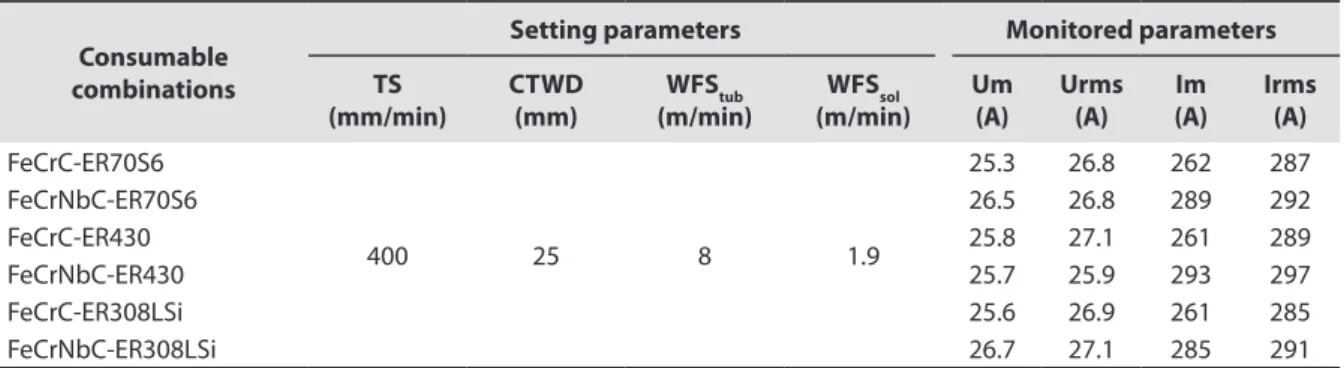
Test plates of SAE 1020 steel, with dimensions of 350 x 50 x 10 mm, were used as substrate. On each of the plate surfaces, 4 parallel 250 mm-long beads were deposited, with a bead center line offset of 7 mm (the second, third and fourth beads overlapped the previous bead by approximately 3 mm). Automatic welding was employed. The S-FCAW wires were positioned perpendicularly to the test plate and the cold wires were continuously fed into the pool from the front, at a pulling angle of 30o in relation to the test plate plane. The same welding parameters setting were used for all the welds, as shown in Table 2. For these settings values, the mean current ranged from 261 to 262 A when the FeCrC wire was used in contrast to a higher value (285-293 A) for the FeCrNbC wire. In both cases, the mean current was not influenced by the cold wire, regardless of the composition (this suggests that the “in situ” formation of the pool did not interfere in the arc properties). This difference between the S-FCAW wires without and with Nb shows that the introduction of Nb made the wire fusion more difficult, demanding approximately more 20 A to melt the same amount of wire per unit of time.
As the tubular and solid wires have different densities and different feed speed, the resulting weight percentage of each wire in the final deposit is estimated. To estimate this difference, the mass of approximately 300 mm of each wire was weighed in an analytical balance (3 samples of each wire). Taking into account the average values
Table 1. Characteristics of the consumables used to obtain the different hardfacing alloys.
FCAW wire Type
Deposited characteristics with no dilution(i)
nominal chemical composition (% wt)
microstructure Hard-ness
HRc
C Mn Si Cr Nb
FeCrC(ii) Cr white cast iron
5.0 1.5 1.5 27 - Primary carbides and eutectic M7C3 carbides in an austenitic matrix
60-64
FeCrNbC(ii) Cr-Nb white cast iron
5.0 0.5 0.7 22 7.0 Cr and Nb carbides in an austenitic matrix
62-65
Solid Wire Type Deposited characteristics with no dilution
(iii)
C Cr Ni Mo Mn Si P S Cu
ER70S-6(iv) Plain carbon steel
0.06-0.15 0.15 0.15 0.15 1.4-1.8 0.8-1.15 0.025 0.035 0.5
ER430(v) Ferritic stainless steel
0.1 15-17 0.6 0.7 0.6 0.5 0.03 0.03 0.75
ER308LSi(v) Austenitic stainless steel
0.03 19-22 9-11 0.8 1-2.5 0.3-0.6 0.03 0.03 0.75
of the masses and the wire feed speeds, the weight percentage of each wire in the combinations was determined (Table 3). In general, the weight percentage of each S-FCAW wire was very similar (about 60%). These calculations made clear the predominance of the S-FCAW wire in the alloy composition.
Table 3. Weight percentage of each wire in the combinations.
Consumable combinations
Weight percentage, %
Tubular wire Solid wire
FeCrC-ER70S6 59.2 40.8
FeCrNbC-ER70S6 59.9 40.1
FeCrC-ER430 59.7 40.3
FeCrNbC-ER430 60.4 39.6
FeCrC-ER308LSi 58.8 41.2
FeCrNbC-ER308LSi 59.6 40.4
To obtain the microstructure characterizations, a cross section of each test plate was taken and metallographically prepared, polishing with 0.3 µm diamond paste. Then etched with aqua regia (75% HCl + 25% HNO3). The metallographic characterization was carried out by Scan Electronic Microscope (SEM), with a magnification of 2000x, in a centralized region of the upper segment of the second bead. Microanalyses by Energy Dispersive Spectrometer (EDS) were also made at these regions to verify the constituent compositions. On the cross sections of the deposits of the FeCrC wire (without Nb), microhardness Vickers (load of 50 g per 15 s) of the primary carbides and the eutectic matrix were determined. The measurement of separate phases (carbides and matrix) of the deposits with FeCrNbC was not possible, due to the high degree of microstructural refinement.
In addition, longitudinal planes of the test plates were obtained by grinding the weld surfaces. These planes were characterized by the presence of pores, typical in this type of deposits. Over these planes, the phases present in the deposits were identified by diffractograms obtained by an X-Ray Diffractometer (40 kV and 30 mA), with CuKα radiation in the range at 20 to 100o, at a speed of 2o/min. Rockwell C hardness, according to ASTM E18 [21], was obtained by applying a load of 150 kgf (7 indentations per sample). Using a portable XRF alloy analyzer, the main alloy elements were identified on these surfaces (carbon was determined separately by volumetric analysis).
To measure the abrasion wear resistance in the longitudinal direction of the deposits, a Dry Sand-Rubber Wheel Apparatus was used, according to ASTM G65 [22], applying procedure B. The sand size range was specified as no. 100, according to NBR 7214 [23], i.e., grains over 150 µm but mostly smaller than 212 µm. From each test plate (corresponding to each wire combination), 3 specimens (65 x 25 x 13 mm) were taken. The surfaces were ground before the test and a pre-wear was applied for 5 minutes. After the pre-wear procedure, the specimens were cleaned by ultrasound in alcohol, dried and weighed in an analytical balance with 0.1 mg resolution. The total abrasion testing time was 30 minutes (wear distance of 4308 m), with weighing intervals every 10 minutes followed
Table 2. Setting and monitored parameters for the welds with combinations of S-FCAW wires and cold wires.
Consumable combinations
Setting parameters Monitored parameters
TS (mm/min)
CTWD (mm)
WFStub
(m/min)
WFSsol
(m/min)
Um (A)
Urms (A)
Im (A)
Irms (A)
FeCrC-ER70S6
400 25 8 1.9
25.3 26.8 262 287
FeCrNbC-ER70S6 26.5 26.8 289 292
FeCrC-ER430 25.8 27.1 261 289
FeCrNbC-ER430 25.7 25.9 293 297
FeCrC-ER308LSi 25.6 26.9 261 285
FeCrNbC-ER308LSi 26.7 27.1 285 291
where: TS = travel speed; CTWD = contact tip to work distance; WFStub = wire feed speed of the FCAW wire; WFSsol = wire feed speed of the
by cleaning, resulting in a total of 9 measurements for each combination of S-FCAW-solid wire. After each 10 minute run, the specimens were cleaned by ultrasound in alcohol, dried and weighed again. A new disc was used in the tests for each of the three specimens. To obtain de density of each deposit, the pycnometer method was employed [24].
3. Results and Discussions
3.1. Microstructural characterization of the hardfacing alloys
Table 4 shows the chemical composition of the alloys, where iron is the remaining component. As expected, all alloys present high Cr and C content. The main differences amongst the alloys are the presences of Nb and Ni, due to the FCAW wire (FeCrNbC), and the austenitic wire (ER308LSi) respectively. In general, the alloys can be classified as Fe-Cr-C ternary system; according to this system, the alloys in Table 4 without Nb would approximate to an eutectic alloy. However, due to the meta-stability condition in which crystallization occurs in welded deposits, a shift of Cr
7C3 to the primary crystallization zone is likely to occur [1].
Table 4. Chemical composition of the hardfacing alloys (wt%).
Hardfacing alloys C Cr Mn Si Nb Mo Ni
FeCrC-ER70S6 2.90 17.49 0.93 1.02 - -
-FeCrNbC-ER70S6 2.93 17.62 0.75 0.69 4.45 -
-FeCrC-ER430 2.92 20.30 0.84 0.94 - 0.018
-FeCrNbC-ER430 2.96 19.96 0.74 0.51 4.46 0.019
-FeCrC-ER308LSi 2.85 20.49 1.08 0.89 - 0.04 1.50
FeCrNbC-ER308LSi 2.88 20.48 0.81 0.50 4.73 0.026 1.33
In the case of the presence of Nb, the NbC carbide crystallizes in advance at temperatures as high as 3500oC, according to Chung et al. [7]. There will be a C depletion in the residual liquid of the ternary system, leading the system to the austenitic zone and resulting in the eutectic formed by austenite and M7C3 carbides.
Figure 1 shows the microstructure of each hardfacing alloy. There are distinct microstructure patterns in the alloys obtained with the FeCrC and the FeCrNbC wires, (Figure 1a, b, c for the former and Figure 1d, e, f for the latter). They are unrelated to the type of the cold wire. The alloys from the FeCrNbC wire present finer microstructure, phenomenon attributed to the presence of Nb. In view of this hypothesis, Nb assists heterogeneous nucleation, forming small NbC during the primary crystallization. These Nb carbides act as heterogeneous nuclei of the M7C3 carbides. Filipovic et al. [9,10], also observed the refinement effect of Nb in hypoeutectic white cast iron. The authors explained that besides heterogeneous nucleation, NbC limits austenitic primary dendrites growth due to a pin effect of the NbC in the matrix. He-Xing et al. [12] demonstrated the Nb effect on the refinement of the eutectic cells for hypoeutectic alloys. Zhi et al. [11] showed the effect of the NbC on the primary crystallization in hypereutectic high chromium cast iron, demonstrating a reduction of the average diameter of the carbides in the microstructure as Nb content is increased in the alloy.
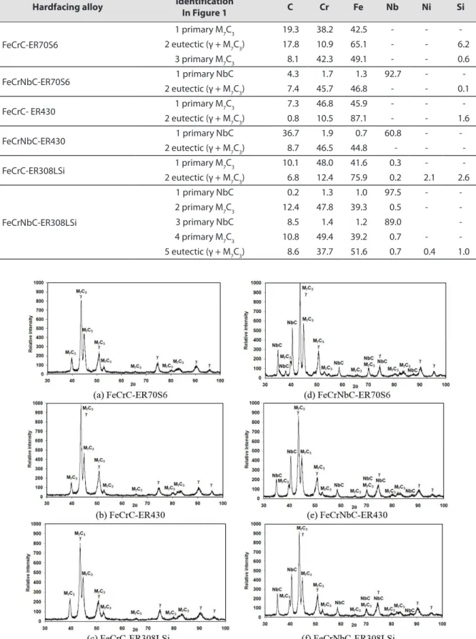
Table 5 shows the chemical compositions of the micro constituents of the alloys. These constituents are identified by numbers in Figure 1 at each microstructure. Figure 2 shows the XRD diffractograms of the different hardfacing alloys, evidencing the present phases. The alloys obtained with the FeCrC wire (Figure 1a, b, c, Figure 2a, b, c and Table 5) show the presence of primary M
7C3 carbides surrounded by an eutectic matrix, composed of small carbides
and austenite (M
7C3 + Feγ). In the polishing plane, the carbides present either hexagonal platelet morphology or a
long spine-like form, which indicate that the carbides are rod-shaped. During the crystallization of hypereutectic cast iron, several authors, among them Chung et al. [7] declare that the M
7C3 carbides nucleates at about 1300
oC
and grows in the liquid to form coarse primary carbides. The matrix formed by the eutectic reaction, is composed of austenite and carbides. In Table 5, Cr and C are concentrated in the carbides, confirming that these carbides crystallized first impoverishing the residual liquid of these elements. Buchely et al. [25], in their comparative studies on SMAW hardfacing, created a map of Cr distribution obtained by EDS and demonstrated that in a hypereutectic alloy this element is present preponderantly in carbides. Chia-Ming et al. [26] studying the effect of an increase of C in hypereutectic deposits, showed through microanalysis that Cr and C concentrate preponderantly in M
carbides. Tang et al. [6] and Chung et al. [27], also researching the effects of Cr and C content in hypereutectic alloys, found the same results. The presence of C and Cr in the matrix is also a clear evidence of the existence of small Cr carbides together with austenite, as reported by Chia-Ming et al. [26] in a study on rich Cr cast iron hypereutectic cladding alloys with various carbon contents.
The alloys obtained using the FeCrNbC wire with the ferritic cold wires (ER70S-6 [16] and ER430 [17]), are characterized by the presence of smaller primary NbC carbides, surrounded by a eutectic matrix composed of austenite
Figure 1. Microstructures of the hardfacing alloys; the numbers indicate the positions at which microanalysis by
Table 5. Chemical composition of the main microconstituents present in the hardfacing alloys (wt%).
Hardfacing alloy Identification
In Figure 1 C Cr Fe Nb Ni Si
FeCrC-ER70S6
1 primary M7C3 19.3 38.2 42.5 - -
-2 eutectic (γ + M7C3) 17.8 10.9 65.1 - - 6.2
3 primary M7C3 8.1 42.3 49.1 - - 0.6
FeCrNbC-ER70S6 1 primary NbC 4.3 1.7 1.3 92.7 -
-2 eutectic (γ + M7C3) 7.4 45.7 46.8 - - 0.1
FeCrC- ER430 1 primary M7C3 7.3 46.8 45.9 - -
-2 eutectic (γ + M7C3) 0.8 10.5 87.1 - - 1.6
FeCrNbC-ER430 1 primary NbC 36.7 1.9 0.7 60.8 -
-2 eutectic (γ + M7C3) 8.7 46.5 44.8 - -
-FeCrC-ER308LSi 1 primary M7C3 10.1 48.0 41.6 0.3 -
-2 eutectic (γ + M7C3) 6.8 12.4 75.9 0.2 2.1 2.6
FeCrNbC-ER308LSi
1 primary NbC 0.2 1.3 1.0 97.5 -
-2 primary M7C3 12.4 47.8 39.3 0.5 -
-3 primary NbC 8.5 1.4 1.2 89.0
-4 primary M7C3 10.8 49.4 39.2 0.7 - -5 eutectic (γ + M7C3) 8.6 37.7 51.6 0.7 0.4 1.0
Figure 2. X-ray diffractograms of the hardfacing alloys rich in Cr: (a), (b) and (c), the Nb free alloys; and (d), (e) and
and fine M7C3 carbides (Figure 1d, e, Figure 2d, e and Table 5). The FeCrNbC-ER308LSi alloy (Figure 1f and Figure 2f) is characterized by the presence of larger primary niobium (NbC) and chromium M
7C3 carbides, in comparison with
the other alloys. The primary carbides are surrounded by a eutectic matrix of austenite and fine M
7C3 carbides
(Figure 1f and Table 5). In this alloy, very small niobium carbides (NbC) appears as nucleation centers of the M
7C3
carbides (numbers 3 and 4 in Figure 1f and Table 5). The presence of Ni in this deposit (Table 3) is evident only in the matrix (Table 4), dissolved in the austenite phase. It is due to the ER308LSi wire [17].
The concentration of niobiun and chromiun in NbC and M
7C3 carbides in the hardfacing alloys is observed in
Table 5, in contrast to the regions identified as the matrix. In general, these microstructures of the Nb bearing alloys are similar to that presented by several authors working with similar white cast irons. Zhi et al. [11], studying the effect of Nb in hypereutectic alloys with 4% C, observed primary NbC carbides in co-existence with M
7C3 when Nb
was increased up to 1.5%. These authors also showed, through microanalysis by EDS and an element distribution map, that Nb concentrates preferably in the NbC carbide. Wang and Li [8], also studying the effect of Nb on the microstructure of hypereutectic alloys for high Cr arc welding hardfacings, confirmed these results. They showed by EDS compositional mapping that niobium is concentrated in the primary NbC. The primary nucleation of NbC in Cr-rich alloys, with consequent decrease of C in the remaining liquid, was also demonstrated by Gregolin and Alcantara [28] for the kind of alloys used in this work.
Microhardness was also used to characterize the carbides and the matrix. Table 6 shows the average values for the hardfacing alloys obtained with the FeCrC wire. There is a wide dispersion of hardness values, as reported by some authors, among whom Stevenson and Hutchings [29]. These authors studied several samples of arc welding hardfacing of high Cr hypereutectic alloys. They found values of 1630 to 2050 Hv for the primary M7C3 carbides and of 750 to 1110 Hv for the eutectic matrix. As the microconstituents in the Nb bearing alloys are very small (Figure 1), determination of their micro hardness was not possible.
Concerning the hardness of the carbides, there is no difference between the values of the FeCrC-ER70S6 and FeCrC-ER308LSi alloys. Although the M7C3 carbide from the alloy FeCrC-ER430 appears to be harder, this observation is not supported statistically when the standard deviation is considered.
The matrix of the FeCrC-ER308LSi hardfacing alloy has a smaller value of microhardness. This result can be related to the austenite in the matrix, as a result of the presence of Ni (Table 5). The FeCrC-ER430 alloy presents a slightly smaller microhardness value than that of the FeCrC-ER70S6 alloy. One reason could be that the high Cr content leads to a primary crystallization of a greater amount of carbides, depressing the C content in the remaining liquid that eventually crystallizes as the matrix.
3.2. Abrasive wear performance of the hardfacing alloys
The comparison of the wear resistances was based on the volume loss values as shown in Figure 3. Volume loss gives a better picture than weight loss, particularly when comparing the wear resistance properties of materials with different densities. Each test corresponds to three10 minute runs or to a total sliding distance of 4308 m. The volume loss was calculated from the mass losses of each run and the material density. A linear trend between the sliding distance and material loss can be concluded from Figure 3. Such behavior is frequently reported in the literature of abrasive wear [2,4,30,31].
Figure 3 also shows that FeCrNbC-ER430 alloy has the highest wear resistance (the lowest volume loss). In general, the alloys produced with the Nb bearing wire (FeCrNbC) in combination with different cold solid wires have higher resistance to abrasion wear. Wang and Li [8] studied the effect of Nb, V and W on wear of hypereutectic
Table 6. Microhardness (Hv
0.05) of the carbides and matrices of the “in situ” alloys with the FeCrC wire
(with 7 indentations each).
FeCrC-ER70S6 FeCrC-ER430 FeCrC-ER308LSi
M7C3 Matrix M7C3 Matrix M7C3 Matrix
FeCrC white cast iron and found that these alloying elements increase significantly the wear resistance in relation to the reference alloy. He-Xing et al. [12] also determined the role of Nb on the abrasive wear resistance, using the rubber wheel test and normalized 3% carbon steel as reference.
The better performance of the hardfacing containing Nb is due to the microstructure refinement effect of Nb. In Figure 1, the finest microstructure corresponds to the FeCrNbC-ER430 alloy and the coarsest to the FeCrNbC-ER308LSi alloy. In addition to microstructure refinement, the presence of hard primary niobium carbides (NbC) is likely to boost the performance of the Nb bearing alloys. This hypothesis is supported by results presented by several authors. He-Xing et al. [12], in a study of the effect of Nb on the abrasion wear of a 15%-Cr white cast iron, found NbC with hardness of around 2400 Hv. The authors state that the matrix of the alloys underwent an increase in hardness, of 693 Hv for a Nb-free alloy to 899 Hv when Nb was added. They also claim that the M
7C3
carbides had their hardness increased from 1686 Hv (Nb-free) to 1818 Hv (Nb bearing). The same phenomena probably occurred to the alloys studied in the present work.
However, another aspect is the wear resistance differences between the Nb bearing alloys. In Table 4, the FeCrNbC-ER430 alloy has the highest C content and the highest wear resistance, while the FeCrNbC-ER308LSi alloy has the lowest C content and the lowest wear resistance. The wear resistance is always higher when the high Cr ferritic solid wire (ER430) is used. On the other hand, the presence of Ni in the matrix of the FeCrNbC-ER308LSi alloy (Tables 3 and 4) contribute to the lower wear resistance by softening the matrix as a result of the contribution of this element in the presence of austenite.
Comparing the wear resistances of the hardfacing alloys without Nb (Figure 3), the FeCrC-ER430 alloy presents highest wear resistance and the finest microstructure (Figure 1). The M
7C3 carbide in this alloy showed
the highest hardness (Table 6), contributing to the best performance. The Nb free alloy (FeCrC-ER70S6) presented the lowest resistance to abrasive wear, probably due to the smaller Cr content (Table 4) and a smaller Cr-Fe ratio in the primary carbide (Table 5). The FeCrC-ER308LSi alloy presented a wear resistance close to the FeCrC-ER70S6 alloy, as a result of the matrix softening by the austenitizing effect of Ni (Table 4 and Table 6).
Figure 4 shows the typical bulk hardness values of the deposits of Fe-Cr based hardfacings. Regardless of the FCAW wire used (FeCrC or FeCrNbC), the bulk hardness is about the same for a given solid wire. The introduction of Nb, in spite of influencing the microstructure and wear resistance, does not govern the deposit hardness. The sizes and types (M7C3 or NbC) of the carbides influences in the bulk hardness but in this study it is not manifested, since other factors like the presence of pores in the samples probably are influencing. The principal factor influencing hardness seems to be the microstructure of the eutectic matrix (Figure 1). The solid wire composition, on the other hand, presents some influence on the hardness, showing the influence of the matrix on this property. The highest hardness was obtained using the ferritic stainless steel wire (ER430), while the lowest hardness was when the austenitic stainless steel wire (ER308LSi) was used. The ferritic wire leads to finer carbides in the eutectic matrix (Figure 1b, e) compared to that produced by the austenitic wire (Figure 1c, f). The presence of Ni in the austenitic matrix also tends to soften the material.
Figure 5 shows the relationship between the deposit hardness and abrasion wear resistances. There is no correlation between the two parameters, coinciding with those reported by several authors, as Zhou et al. [3], for this type of alloys, because the abrasion resistance of a hardfacing alloy depends on many other factors such as the type, shape and distribution of hard phases, as well as the toughness and strain hardening behavior of the matrix [8,9]. The FeCrC-ER430 and FeCrNbC-ER430 alloys have practically the same hardness, but the wear resistance of the latter is almost twice that of the former. These data indicate that the solid wire composition governs the hardness, while the FCAW wire governs the wear resistance.
Figure 4. Hardness in tested alloys.
Figure 5. Correlation between the bulk hardness and abrasion wear resistance of the hardfacing alloys.
3.3 Analysis of the worn surfaces
Figure 6 shows the surface of the hardfacing samples after the wear tests. All wear scars presented transversal cracks, typical of hardfacing. This is in agreement with Wang and Li [8], who show similar worn surfaces and attribute this wear resistance characteristic to the stress relief caused by cracking.
detachment of material amongst the three Nb deposits was observed in the FeCrNbC-ER430 deposit probably because no interconnected micro-cracks were present. However, in the Nb free alloys, no micro-cracking was present, yet they presented higher wear. One reason for this contrasting behavior could be related to microstructural characteristics (such as coarser microstructures and absence of harder carbides of the MC types). Figure 7 shows magnifications of the scars of the FeCrC-ER430 and FeCrNbC-ER430 alloy specimens; showing that for the alloy without Nb the presence of deeper grooves is visible, although for the Nb bearing alloy material detachment is visible.
Figure 7. Magnified wear scars of two alloys, obtained with ER430 solid wire (1- longitudinal deep grooves;
2- longitudinal not deep grooves; 3- brittle detachment).
Figure 6. Wear scars of the different deposits after Dry Sand-Rubber Wheel tests (1- transversal cracks; 2- longitudinal
4. Conclusions
Different chemical compositions were achieved “in situ” by feeding chemically different cold wires (low carbon ferritic steel, high chrome ferritic steel and austenitic steel) into a pool produced with conventional flux-cored wires (FeCrC and FeCrNbC) by self-shielded flux-cored arc welding (S-FCAW). The results showed that Nb added to the deposit refines the microstructure and promotes the formation of very hard NbC carbides, although bulk hardness was not influenced by Nb introduction in the alloy. These microstructural changes made the deposit more wear resistant and it is likely to be the governing parameter for wear resistance enhancement.
For the case of the two tubular wires, a cold solid wire with high Cr and low C (ferritic stainless steel) boosts more significantly the wear resistance than the wires with Ni, high Cr and low C (austenitc stainless steel) or without Cr (low carbon steel). The richer in C, the higher the hardness of the carbides. However, the effect of Nb present in one of the tubular wires was more predominant in the abrasion resistance than the composition variation due to solid wire addition. In all cases, the wear mechanism was micro-ploughing and micro-cutting, with some detachment fragile when Nb is present.
Considering the chemical composition changes obtained by addition of cold wire together with the tubular wire of S-FCAW, this approach demonstrated the possibility of boosting the resistance to abrasion wear (of dry sand particles) of white cast iron hardfacing layers deposited by arc welding.
Acknowledgements
The authors acknowledge the infrastructural and technical support of the Center for Research and Development of Welding Processes and the Laboratory of Tribology and Materials of the Federal University of Uberlandia. They also acknowledge the financial support of the Brazilian agency for personal development (CAPES), through project Capes-MES 0146/2012.
References
[1] Bálsamo PSS, Scotti A, Mello JDB. Microstructure interpretation of a hardfacing layer deposited by welding by use of the diagram Fe-Cr-C líquidus surfaces. Revista Soldadura. 1995;25(4):199-207. [2] Buchanan VE, McCartney DG, Shipway PH. A comparison of
the abrasive wear behavior of iron-chromium based hardfaced coatings deposited by SMAW and electric arc spraying. Wear. 2008;264:542-549. http://dx.doi.org/10.1016/j.wear.2007.04.008. [3] Zhou Y, Yang YL, Li D, Yang Q-X. Effect of titanium content on
microstructure and wear resistance of Fe-Cr-C hardfacing layers. Welding Journal. 2012;91:229-235.
[4] Çetinkaya C. An investigation of the wear behaviors of white cast irons under different compositions. Materials & Design. 2006;27(6):437-445. http://dx.doi.org/10.1016/j.matdes.2004.11.021. [5] Chatterjee S, Pal TK. Solid particle erosion behavior of hardfacing
deposits on cast iron—influence of deposit microstructure and
erodent particles. Wear. 2006;261(10):1069-1079. http://dx.doi. org/10.1016/j.wear.2006.02.004.
[6] Tang XH, Chung R, Pang CJ, Li DY, Hinckley B, Dolman K. Microstructure of high (45 wt. %) chromium cast irons and their resistances to wear and corrosion. Wear. 2011;271(9-10):1426-1431. http://dx.doi.org/10.1016/j.wear.2010.11.047.
[7] Chung RJ, Tang X, Li DY, Hinckley B, Dolman K. Microstructure refinement of hypereutectic high Cr cast irons using hard carbide-forming elements for improved wear resistance. Wear. 2013;301(1-2):695-706. http://dx.doi.org/10.1016/j. wear.2013.01.079.
[8] Wang Q, Li X. Effects of Nb, V, and W on microstructure and abrasion resistance of Fe-Cr-C hardfacing alloys. Welding Journal, USA. 2010;89:133-139.
[9] Filipovic M, Kamberovic Z, Korac M, Gavrilovski M. Microstructure and mechanical properties of Fe–Cr–C–Nb white cast irons. Materials & Design. 2013;47:41-48. http://dx.doi.org/10.1016/j. matdes.2012.12.034.
[10] Filipovic M, Kamberovic Z, Korac M, Jordovic B. Effect of niobium and vanadium additions on the as-cast microstructure and properties of hypoeutectic Fe–Cr–C alloy. ISIJ International. 2013;53(12):2160-2166. http://dx.doi.org/10.2355/isijinternational.53.2160. [11] Zhi X, Xing J, Fu H, Xiao B. Effect of niobium on the as-cast
microstructure of hypereutectic high chromium cast iron. Materials Letters. 2008;62(6-7):857-860. http://dx.doi.org/10.1016/j. matlet.2007.06.084.
[12] He-Xing CH, Zhe-Chuan C, Jin-Cai L, Huai-Tao L. Effect of niobium on wear resistance of 15%Cr white cast iron. Wear. 1993;166(2):197-201. http://dx.doi.org/10.1016/0043-1648(93)90262-K. [13] Mendez PF, Barnes N, Bell K, Borle SD, Gajapathi SS, Guest
SD, et al. Welding processes for wear resistant overlays. Journal of Manufacturing Processes. 2014;16(1):4-25. http://dx.doi. org/10.1016/j.jmapro.2013.06.011.
[14] Garcia DBC, Ferraresi VA. Influence of welding technique and the type of filler metal in the wear resistance of hardfacing weld deposits. In: Associação Brasileira de Ciências Mecânicas. Proceedings of the 21st Brazilian Congress of Mechanical Engineering – COBEM, 2011 October; Natal, Brazil. Rio de Janeiro: ABCM; 2011. p. 1-8.
[16] American Welding Society. A5.18/A5.18M-01: specification for carbon steel electrodes and rods for gas shielded arc welding. Miami: AWS; 2001.
[17] American Welding Society. A5.9-93: specification for bare stainless steel welding electrodes and rods. Miami: AWS; 1993. [18] Welding Alloys Group. Products & services: anti-abrasion [internet
page]. 2016. [access 25 feb. 2016]. Available from: http://www. welding-alloys.com/products-services/wa-welding-consumables/ hardfacing-cored-wires/anti-abrasion.html
[19] German Institute for Standardization. DIN EN 14700: welding consumables: welding consumables for hard-facing specification for bare stainless steel welding electrodes and rods. Berlin: DIN; 2014.
[20] Weld-inox: Soldas Especiais. Produtos: arames. [internet page]. São Paulo; 2016. [access 25 feb. 2016]. Available from: http:// www.weldinox.com.br
[21] American Society for Testing and Materials. ASTM E18-00: standard test methods for rockwell hardness of metallic materials. West Conshohocken: ASTM; 2000.
[22] American Society for Testing and Materials. ASTM G65-00: standard test method for measuring abrasion using the dry sand/ rubber wheel apparatus. West Conshohocken: ASTM; 2000. [23] Associação Brasileira de Normas Técnicas. NBR 7214: standard
sand for analysis of cement. Rio de Janeiro: ABNT; 1982. [24] Perry RH, Green DW. Perry’s Chemical Engineers´ Handbook.
México: Mc Graw Hill; 1999. 2582 p.
[25] Buchely MF, Gutierrez JC, León LM, Toro A. The effect of microstructure on abrasive wear of hardfacing alloys. Wear. 2005;259(1-6):52-61. http://dx.doi.org/10.1016/j.wear.2005.03.002.
[26] Chia-Ming C, Li-Hsien C, Chi-Ming L, Jie-Hao C, Chih-Ming F, Wu W. Microstructure and wear characteristics of hypereutectic Fe–Cr–C cladding with various carbon contents. Surface and Coatings Technology. 2010;205(2):245-250. http://dx.doi. org/10.1016/j.surfcoat.2010.06.021.
[27] Chung RJ, Tang X, Li DY, Hinckley B, Dolman K. Abnormal erosion–slurry velocity relationship of high chromium cast iron with high carbon concentrations. Wear. 2011;271(9-10):1454-1461. http://dx.doi.org/10.1016/j.wear.2011.01.087.
[28] Gregolin JAR, Alcantara NG. Dendritic γ - to massive (Fe,Cr)7C3
transition in Cr-Nb white cast iron microstructures. Journal of Materials Science Letters. 1991;10:751-752. http://dx.doi. org/10.1007/BF00723268.
[29] Stevenson ANJ, Hutchings IM. Wear of hardfacing white cast irons by solid particle erosion. Wear. 1995;186-187:150-158. http://dx.doi.org/10.1016/0043-1648(95)07184-9.
[30] Buchanan VE, Shipway PH, McCartney DG. Microstructure and abrasive wear behavior of shielded metal arc welding hardfacings used in the sugarcane industry. Wear. 2007;263(1-6):99-110. http://dx.doi.org/10.1016/j.wear.2006.12.053.
[31] Yang J, Yang Y, Zhou Y, Yang Q. Microstructure and wear properties of Fe-2 wt-% Cr-X wt-% W-0.67 wt-% C hardfacing layer. Welding Journal, USA. 2013;92:225-230.