Fiabilitate si Durabilitate - Fiability & Durability No 1/ 2013 Editura “Academica Brâncuşi” , Târgu Jiu, ISSN 1844 – 640X 42
BERNOULLI QUARTIC GENERATION BY AN ORIGINAL
MECHANISM
Prof.dr.ing. Iulian POPESCU , University of Craiova
Conf.dr.ing. Mirela CHERCIU, University of Craiova, [email protected]
Abstract: The paper is based on a geometrical method for generating Bernoulli Quartic and
design a mechanism that can generate it. The found mechanism is R-RTT-RTR - Triad of order 3. The analytical equations are obtained through the outlines method and the desired curve is obtained using a computer program. The curve is generated and the functioning of the generating mechanism is analyzed on the basis of some diagrams.
Keywords: Bernoulli quartic, 2D curves, mechanisms generating curves
1. INTRODUCTION
2D curves can be generated by graphical methods, with computer, either using their equations or with mechanisms. Over time these curves were drawn with traditional drawing tools, but many mathematicians have built mechanisms in the form of models, to check if one can get the desired curves. Are known in this type of work Cebâşev [2], Reuleaux [5] and others. Artobolevskii [1] has created several mechanisms generating curves from geometric considerations. In [4] are given some original mechanisms that generate 2D curves. In [3] are given many 2D and 3D curves with their equations and geometric considerations. From here we started this work, building a mechanism that generates the Bernoulli quartic.
2. INITIAL DATA
Bernoulli quartic (fig. 1) was studied in 1687 by Jacques Bernoulli and Leibniz in 1696.
Fig.1 Bernoulli quartic [3] Fig.2 Geometric data [3]
In [3] it is given this curve and it’s Cartesian equation:
2 2 2 2 2 2 ) 2 b a ( y y ) 2 b a ( y x (1)
Fiabilitate si Durabilitate - Fiability & Durability No 1/ 2013 Editura “Academica Brâncuşi” , Târgu Jiu, ISSN 1844 – 640X 43
3. SINTHESIS OF THE GENERATOR MECHANISM
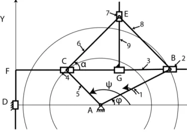
Geometrically, a line moving with the ends on two concentric circles (fig. 2), is always parallel to itself so that the middle point of this line describes
a branch of Bernoulli quartic.
For the synthesis of the mechanism was started from the following considerations: - the straight line has variable length, so it takes two slides on the C and B (fig. 3); - the straight line has a circular translational motion , so it is necessary a slide in D, providing vertical movement of the straight line, parallel to the previous position;
- the slides of C and B are required rotational joints to ensure rotation AB and AC elements , with C and B on the concentric circles;
- point G should be set at the middle of the variable segment BC, so adding BECG kinematic chain.
4. THE MECHANISM ANALYSIS
The mechanism is quite complex, with the structural scheme of fig. 4. It consists (fig. 5) of driving element 1, dyad DFBB, type RTT, dyad ACC, type RTR and triad of order 3, CEBG. So the mechanism is type: R-RTT-RTR-Triad of order 3.
Fig. 3. The achieved mechanism
Fiabilitate si Durabilitate - Fiability & Durability No 1/ 2013 Editura “Academica Brâncuşi” , Târgu Jiu, ISSN 1844 – 640X 44
Fig. 4. The structural scheme Fig. 5. The kinematic groups
The following relations are written:
(2)
(3)
(4)
(5)
(6)
(7) (8)
(9)
(10)
(11)
(12)
(13)
(14)
(15)
(16)
5. THE OBTAINED RESULTS
Fiabilitate si Durabilitate - Fiability & Durability No 1/ 2013 Editura “Academica Brâncuşi” , Târgu Jiu, ISSN 1844 – 640X 45
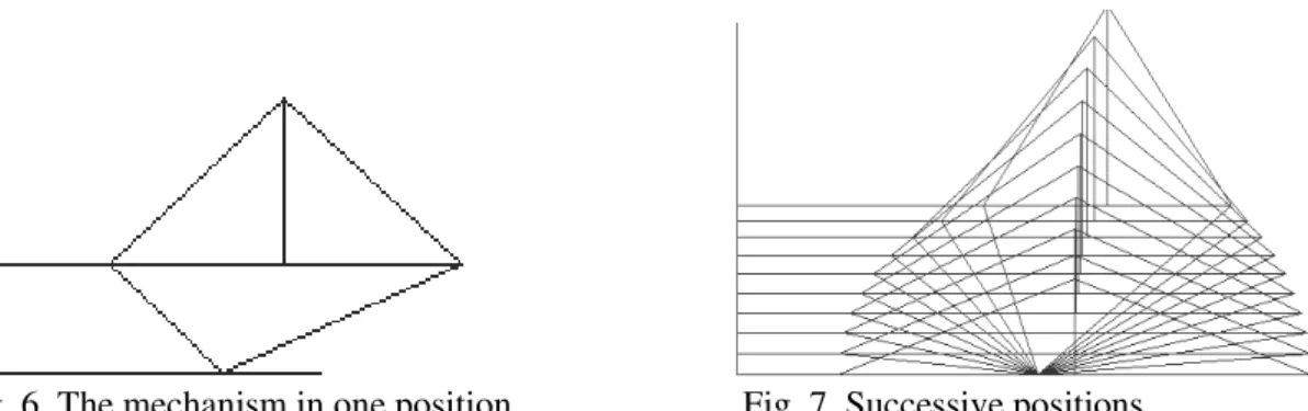
Fig. 6. The mechanism in one position Fig. 7. Successive positions
Because the mechanism moves only in a narrow field, two lenghts have changed the values: AB=50, AC=130, resulting the successive positions of the mechanism in fig. 7.
It appears that the mechanism is well built since G is always in the middle of variable length BC. However, it also noted the following:
- The obtained curve (Fig. 8) is not the required one; - AC>AB unlike the indication in fig.2.
By attempts, resulted fig. 9 at AB = 50, AC = 69, achieving a branch of the curve similar to the desired curve.
For AB = 55, AC = 69 was obtained the curve in fig. 10, which is precisely the required curve.
Fig. 8. Initial curve Fig. 9. An alternative of the curve Fig. 10. The desired curve
Successive positions of the mechanism for the curve in fig. 10, are given in fig. 11. More in detail the successive positions are shown in fig. 12 ( =0…90), fig. 13 ( =90…180), fig.
Fiabilitate si Durabilitate - Fiability & Durability No 1/ 2013 Editura “Academica Brâncuşi” , Târgu Jiu, ISSN 1844 – 640X 46
Fig. 11 Successive positions for the desired curve Fig. 12. Successive positions in quadrant I
Fig. 13. Successive positions Fig. 14. Successive positions Fig. 15. Successive positions in quadrant II in quadrant III in quadrant IV
For the curve in fig. 10, the data sliders CG and BG variations are given in fig. 16, observing that they are equal, so they are on the same curve in the diagram, ie confirming that the mechanism ensures that point G is in the middle of the variable segment BC.
0.0 100. 200. 300. 400.
Fi [grd] 0.0
20. 40. 60. 80.
CG
B G
0.0 100. 200. 300. 400.
Fi [grd] 0.0
25. 50. 75. 100. 125.
C
B
Fiabilitate si Durabilitate - Fiability & Durability No 1/ 2013 Editura “Academica Brâncuşi” , Târgu Jiu, ISSN 1844 – 640X 47
The change of distance CB is given in fig. 17, similar to fig. 16, but for some other values.
It’s noticed that CB decreases, reaches a minimum and then increases, the curve’s branches
being symmetrical.
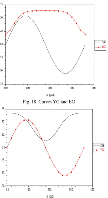
In fig. 18 are observed the curves for EG and YG quota. YG has sinusoidal variation and ED increases at first, remains approximately constant in a field, then decreases, its branches are symmetrical.
Fig. 18. Curves YG and EG
0.0 100. 200. 300. 400.
Fi [grd] -75.
-50. -25. 0.0 25. 50. 75.
X G Y G
Fig. 19. Curves XG and YG
0.0 100. 200. 300. 400.
Fi[grd] -75.
-50. -25. 0.0 25. 50. 75.
YG
Fiabilitate si Durabilitate - Fiability & Durability No 1/ 2013 Editura “Academica Brâncuşi” , Târgu Jiu, ISSN 1844 – 640X 48
In fig. 19 are shown the coordinates variations of the tracer point, G. YG and XG sine and cosine varies. Curves are continuous, so the mechanism does not break the cycle.
6. CONCLUSIONS
- It’s started from geometric considerations and it was obtained the generating
mechanism;
- the lengths of some kinematic elements were adjusted by attempts, up to the required curve obtained;
- it was made a structural analysis of the mechanism, observing that it has two dyads and a triad;
- the required curve was obtained;
- the movement of the mechanism was studied, based on the curves of variable sliders and successive positions (in the quadrants).
REFERENCES
[1] Artobolevskii, I.I, Mehanizmî v sovremennoi tehnike, vol. I-V, Izd. Nauka, Moskva, 1971.
[2] Cebâşev, P.L. –Izobrannâe trud, Izd. Nauka, Moskva, 1953.
[3] Ferrol, R. –Encyclopedie des formes remarquables courbes, surfaces, fractals, polyedres.
2006-2011 [http://www.mathcurve.com/]:
[4] Popescu, I., Luca, L., Cherciu, M. – Structura şi cinematica mecanismelor. Aplicaţii. Editura SITECH, Craiova, 2013.