Brazilian Journal of Physics, vol. 35, no. 3B, September, 2005 763
Development of a CCD-Based Image Acquiring System for Neutrons at the
Argonauta Reactor
Marcelo J. Gonc¸alves, Ricardo Tadeu Lopes,
Universidade Federal do Rio de Janeiro - COPPE - Bloco 6, 21945-970, Rio de Janeiro, RJ, Brazil
Maria Ines Silvani, Gevaldo L. de Almeida, and Rosanne C. A. A. Furieri Instituto de Engenharia Nuclear - CNEN - C.P. 68550,
Ilha do Fund˜ao, 21945-970, Rio de Janeiro, RJ, Brazil
Received on 6 July, 2005
A thermal neutron image acquiring system is being developed at theInstituto de Engenharia Nuclear-IEN (CNEN). This system would be capable to perform non-destructive assays after 2D images acquired on a real or quasi real time basis as well as 3D tomographic images reconstructed from the two-dimensional ones. The source-detector set is constituted by the Argonauta reactor - furnishing a thermal neutron flux of 4.46×10
5n · cm−2
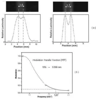
·s−1- and by a converter-scintillating screen for this kind of radiation. After a 90odeviation from its original path through a dark chamber provided with a properly positioned mirror, the light emitted by this screen is captured by a CCD-based video-camera coupled to a microcomputer which processes the data and supplies the final digital images. As a previous step aiming at the gathering of parameters and features to characterize the system, a conventional photo camera has been used instead of the video-camera being yet purchased. This work presents the qualitative and quantitative results obtained by using this preliminary system, such as 2D images of several objects and theModulation Transfer Function-MTFrespectively. Besides that, a comparison is made between the results achieved by using this system and those arising from a traditional neutrongraphy employing radiographic films.
I. INTRODUCTION
The different attenuation coefficients of a material for ther-mal neutrons and X-rays make these radiations complemen-tary tools for non-destructive assays. Indeed, samples contai-ning different material could be utterly transparent or opaque to one kind of radiation but would reveal its inner features to the other kind. Such features motivated the development of 2D tomographic systems incorporating conventionalas well as position sensitive detectors and the Argonauta reactor as source of thermal neutrons [1,2]. Although conventional neu-trongraphy using radiographic films exhibit better resolution, they only cast a kind of shadow of the attenuating materials inside the sample, but not a slice of it as a tomography does. However, a price in terms of acquisition time has to be paid for such a refined information: while a neutrongraphy carried out under the available thermal neutron flux of 105n·cm−2
·s−1 requires about 40 min, the tomography demands 2 to 6 hours depending on the type of the system employed. The aim of the present work is the development of a system capable to acquire neutrongraphic images of an object on a real time ba-sis and the processing through a proper unfolding software of the images taken at different angles to reconstruct a 3D at-tenuation map the object being inspected. This system uses a 2D detector constituted by a screen containing a scintilla-ting material capable to transform the energy of the incident radiation into visible light, and a proper camera to catch that light. Employing a video-camera it would be possible to ac-quire a sequential set of frames within a short time making thus feasible to assay dynamic structures. Since the neutrons themselves due to their lack of electric charge cannot under-take any ionization, the scintillating screen should contain a
material capable totranslatetheir presence into an ionization event, through a proper nuclear reaction. Materials containing isotopes such as6Li,10B,155Gd,157Gd are widely employed for this purpose. Some basic concepts, as well as the metho-dology and results achieved in the first step of this work ai-ming at the development of a 5thgeneration tomographic
sys-tem is presented as follows. For the sake of characterization of the system, parameters and images of some objects have been obtained by using a conventional 50 mm/f1.8, 35 mm photo-camera instead of the ultimate video-camera being yet purchased. The 15x10cm scintillating screen is constituted by silver-activated Li6F(ZnS), being commercially available as
NE426.
II. SCINTILLATION MECHANISM
The 6Li in the scintillating screen is the responsible for the neutron-to-charged particle conversion through the reac-tion6Li + n =3H + α+ 4,78 MeV. The changing electrical
764 Marcelo J. Gonc¸alves et al.
within the visible range [3], as outlined in the Fig.1.
FIG. 1: The energy loss of the electron in a stepwise fashion rather than a single jump, allows the emission of radiation within the visible range.
III. MODULATION TRANSFER FUNCTION
The Modulation Transfer Function-MTFis a tool used to quantifythe quality of the image furnished by an image ac-quiring system. This function shows how the ability of the system to distinguish single features is impaired by the gap between them. This is done by plotting the modulation, defi-ned as the ratio of amplitude-to-mean value, versus the spatial frequency. When this spatial frequency increases, the Line Spread Function-LSFrepresenting the system resolution be-gin to overlap increasing the mean value and reducing the am-plitude, as shown in Fig.2. As consequence, the modulation decreases as the frequency increases.
FIG. 2: The LSF representing the system resolution overlap at high frequencies diminishing thus the modulation.
The MTF can be obtained by the discrete Fourier Trans-form of theLine Spread Function-LSF[4] but it requires the knowledge of its profile what is not a readily achievable task. It can be also obtained by using a special collimator provi-ded with constant aperture slits and increasing spatial fre-quency, but such collimators are very expensive or not avai-lable at all. In this work a simplified alternative of this appro-ach has been employed by using several individual twin-slit collimators with different gaps to simulate a variable spatial frequency.
IV. EXPERIMENTAL AND RESULTS
The NE 426 scintillating screen reacts to the incident neu-trons by emission of visible light with a peak of intensity occurring at about 450 nm, which corresponds to the bluish-green light in the electromagnetic visible spectrum.
The image acquiring system as outlined in the Fig. 3 which is self-explainable, uses a dark chamber provided with a first-surface mirror to deflect the light at 90o, precluding thus the direct incidence of radiation in the camera.
FIG. 3: Scheme of the image acquiring system. A conventional photo-camera has been preliminary used during the first phase of this work.
After the development of the film, the caught image is trans-formed through a proper digitalization into set of 3 matrices expressing the saturation for the basic colors, red, green and blue (RGB system). Since the main information concerning the beam attenuation is brought mainly by the blue matrix, the remaining ones can be ruled out without a substantial loss of quality in the final image.
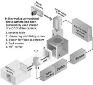
TheModulation Transfer Function-MTFfor the system has been measured aiming at the evaluation of the spatial resolu-tion of the employed screen. The Fig.4a shows the experimen-tally obtained rough data used toconstructthe MTF shown in Fig.4b. Those data have been gathered by using three gadoli-nium masks, each of them provided with a pair of 1mm-width slits disposed at different gaps, defining thus different spatial frequencies. This collimator simulates approximately there-fore the response of the system to two line sources, as an over-lapping of twoLine Spread Functions-LSF, which are specific for each system. The curves shown in Fig. 4a have been obtai-ned by using the softwareMATLABto digitalize the intensity of the blue tonality along a straight line perpendicular to the slits.
Brazilian Journal of Physics, vol. 35, no. 3B, September, 2005 765
FIG. 4: Every point of the MTF was determined by the amplitude-to-mean value ratio from curves in (a).
approximately. These results have been compared with those ones obtained with the conventional neutrongraphy using ra-diographic films. Due to their intrinsic high resolution the related LSF for these films is very narrow and only begin to entangle at very high spatial frequencies which lies far beyond the range of the available collimators.
Some images of different objects as displayed by scintillating-converter screen and caught by a conventional photo-camera are shown in Fig.5-7.
FIG. 5: Images after 30 seconds exposition time lapse. Water-filled plastic syringe containing an air bubble (left). Water-filled glass cup containing a stainless steel spoon (right).
The Fig.6 (top) shows the otherwise unknown inner struc-ture of a automobile fuel injector gauge, revealing the pre-sence of neutron-absorbing internal components as well ex-ternal ones, such as rubber o-rings.
The Fig.6 (bottom) shows a ball-bearing where the voids between the balls formerly filled with grease appear as dark regions. The grease has later on been removed in order to take the conventional picture.
A neutrongraphic image of a cadmium foil provided with 0.5mm-diameter orifices placed at about 0.5 mm apart from each other is shown in Fig. 7. The system was unable to resolve the individual orifices which appear as somewhat
con-FIG. 6: (top) Automobile fuel injector. The rubber o-rings and plas-tic parts appear as dark areas. (bottom) Ball bearing. The grease between the balls (removed to take the conventional photo) appears as dark spots.
tinuous blurred stripe.
FIG. 7: Image of a cadmium foil provided with 0.5 mm-diameter orifices.
Although the images acquired after the traditional neutron radiography using films exhibit a much better resolution, they demand a much high exposition time lapse. Moreover, the use of a video-camera would enable to acquire images of moving objects. Besides that, a set of digital images taken from an object under different angles, as provided by a video-camera, could be unfolded through a proper reconstructing algorithm to yield a 3D image. Such tasks are utterly impossible or very cumbersome to be accomplished for a system employing ra-diographic films. A brief qualitative comparison between the images furnished by the proposed system and the conventio-nal neutrongraphy using radiographic films is shown in Fig.8 and 9.
FIG. 8: (a) Neutrongraphy using a scintillating screen. (b) Conventi-onal neutrongraphy.
766 Marcelo J. Gonc¸alves et al.
Fig. 9.
FIG. 9: (a) Neutrongraphy using a scintillating screen. (b) Conventi-onal neutrongraphy.
V. CONCLUSIONS
The radiographic images acquired with thermal neutrons using a converter-scintillating screen as 2D-detector
demons-trated the feasibility to develop a 3D-tomographic system.
In spite of the low neutron flux available at the main chan-nel of the Argonauta research reactor, the lack of an image intensifier, and a CCD-camera, this work has succeed in de-termining the Modulation Transfer Function - MTF for the system and to obtain fair quality images of different types of objects.
Both quantitative and qualitative results have been achie-ved by using a conventional photo-camera to catch the picture drawn on the converter-scintilllating screen. Further works will include the replace of that device by a CCD-camera, ma-king thus possible a faster image acquisition, their storage in electronic form, and their processing by a proper image re-constructing software to obtain a final 3D image.
[1] M. I. Silvani, et al, Conversion of a X-ray position sensitive de-tector for use in a thermal neutron tomographic system, Nuclear Instruments and Methods in Physics Research B213,294 (2004). [2] M. I. Silvani, et al, Evaluation of a Computer aided Neutron To-mografic System Incorporating a Gaseous Position Sensitive De-tector, Nuclear Instruments and Methods in Physics Research A, 505, 568 (2004).
[3] F. G. Knoll, Radiation Detection and Measurement, ed. 2, USA, John Wiley and Sons(1989).
[4] ASTM E 1441-95 and 1570-95a, Non-Destructive Testing, Ra-diation Methods, Computed Tomograph. Guide for Imaging and Practice for Examination, ISO/TC 135/SC 5, N 118, USA (1996.)