Influence of high frequency and moderate energy pulses on DLC deposition onto metallic
substrates by magnetron sputtering technique
R. M. Oliveira1, L. Hoshida1;2, M. Ueda1, and K. Baba3
1INPE – Instituto Nacional de Pesquisas Espaciais, PO Box 515, ZIP 12227-010
Av. dos Astronautas, 1758 - S˜ao Jos´e dos Campos, S˜ao Paulo, Brazil
2ITA – Instituto Tecnol´ogico de Aeron´autica, ZIP 12228-900
Pc¸. Marechal Eduardo Gomes, 50 - S˜ao Jos´e dos Campos, S˜ao Paulo, Brazil and
3ITCN - Industrial Technology Center of Nagasaki, 2-1303-8, Ikeda, Omura
Nagasaki 856-0026, Japan
(Received on 17 April, 2009)
The deposition of Diamond-like carbon (DLC) films brings excellent mechanical, chemical, optical and elec-tronic properties to a large range of materials. However, a problem to be overcome is its poor adhesion on metallic substrates. Usually, a silicon layer must be deposited on the surface of metals previous to DLC film deposition. In fact, in our experiments using conventional Magnetron Sputtering (MS) technique for deposition of DLC film on metal surfaces (AISI 304 stainless steel, Al 2024, Ti-6Al-4V), the silicon interlayer was crucial to avoid delamination. However, a combined process using MS and high frequency and moderate energy pulses (2.5kV/6µs/1.25 kHz), was successful to grow DLC film without the interlayer. Additionally, by monitoring the stress and the thickness in silicon samples after the processes, it was possible to correlate the conditions of op-eration with such characteristics. Stress measurements carried out by a profilometer and calculated by Stoney´s equation varied from 2 GPa to 10.5 GPa depending on the conditions of operation of the process (pressure, distance source-substrate, frequency, length and intensity of the pulse). The thickness, the composition, the structure and the morphology of DLC coatings deposited in such metallic surfaces were obtained. Tribological and corrosion tests were also performed.
Keywords: diamond-like carbon, corrosion, implantation, surface characterization
I. INTRODUCTION
The advanced mechanical, electronic and optical proper-ties of DLC films make them useful for wide-ranging appli-cations. In particular, metallic substrates deposited with DLC present high level of hardness [1], low friction coefficient [2,3], high wear resistance [4], besides chemical inertness. However, good adhesion to steel and other metallic substrates is desired to avail the DLC film coating more widely [5]. The main cause of poor adhesion film-substrate in DLC coating is the excessive intrinsic stress in the thin film [6].
The adhesion among DLC and metallic substrates has been a concern of various studies [7-9]. Several strategies to reduce the stress in as-deposited DLC films have been proposed, such as incorporating thin layers of different metals (Cr, Ti, Ta, W, e.g.) [10-13]; silicon and boron [14]; multi-layers (SiC, TiC, TiN, CrN, e.g.) [15,16]; or post-deposition anneal-ing [17,18]. Alternatively, successful DLC coatanneal-ings onto met-als were obtained by combining Physical Vapor Deposition (PVD) and Plasma Immersion Ion Implantation (PIII) [19].
In this work, metallic surfaces (AISI 304 stainless steel, Al 2024, Ti-6Al-4V) were coated with DLC film and im-planted with carbon ions in a combined process using mag-netron sputtering and PIII. To achieve this, moderate energy and high frequency pulses were applied to the substrates dur-ing film growth. In the process, a plasma sheath is formed during the on time of the pulses, accelerating ions towards the substrate. These ions are implanted into the substrate and the growing film. Conventional magnetron sputtering deposition takes place between pulses.
Electronic address:[email protected]
Amongst the conventional magnetron sputtering deposi-tion, in the combined process the growing film is subjected to highly repetitive bombardment of moderate energy ions, that have the effect of reliving the stress in the coating [20]. In the beginning of the process, ions will penetrate the sur-face of the substrate, creating a mixing layer, which may help to improve the adhesion between the film and the substrate. Other advantage of this combined process concerns with the moderate heating of the substrate due to ion bombardment, which additionally helps with stress relief.
II. EXPERIMENTAL
Individual circular magnetron sputtering source, 50mm di-ameter, fed by a 600W RF power supply, was mounted on the top of a 60 l volume stainless steel chamber. Carbon graphite 99.999% pure, 2mm thick, was used as the sputtering target.
A stationary circular sample holder, 10 cm diameter, placed at the mid-plane of the vacuum chamber can accommodate until 12 samples. The distance source-substrate can be varied from 0 cm until 15 cm by moving the sputtering source inside the vessel.
A compact pulsed high voltage generator [21] is capable of delivering pulses of up to 7 kV, of 10µsin pulse length at a repetition rate up to 2.5 kHz, to the samples during DLC coating.
Vacuum pressure during the process was varied from 5× 10⁻³mbar to 2
×10−2mbar.
Stainless steel (AISI SS 304), titanium alloy (Ti6Al4V) and aluminum alloy (Al 2024) were used as the substrates. Silicon was used in some cases as a monitor of the process.
X-ray photoelectron spectroscopy (XPS) was used to char-acterize the composition of the treated surface. The film structure was evaluated by Renishaw Raman spectrometer with a 514.5 nm Ar-ion laser.
Friction coefficient was measured by a pin-on-disk CSM tribometer. The corrosion resistance of the treated materi-als was measured by a potenciostat/galvanostat, with three electrode configuration inside an electrolytic cell. The cell contained a solution with 3.5% of NaCl with pH equal to 6. The potentials were measured with respect to a reference elec-trode made of Ag/AgCl. A Tencor surface profiler was used to measure the substrate curvatures for the obtainment of the stress of the deposited films. Roughness of DLC films on the surface of silicon samples was measured by Atomic Force Microscope (AFM) Veeco Multimode. It is composed of a NanoScope V controller, able to capture high-pixel-density images (5120×5120) and it incorporates software which is used to get the roughness number.
III. RESULTS AND DISCUSSION
In a magnetron sputtering (MS) system the deposition rate and the film uniformity are two important parameters to be monitored and controlled. On one hand, deposition rates are affected primarily by the sputtering power, source-to-substrate distance, sputter gas pressure, and target material type. On the other hand, the uniformity of film thickness is primarily affected by the geometry of the sputtering pro-cess, including the source-to-substrate (throw) distance and secondarily by sputtering power, sputtering pressure, and tar-get composition and structure.
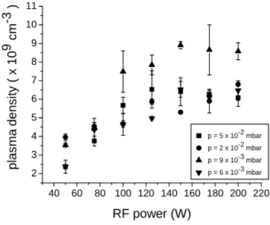
In order to help to set optimized window of operation for this MS system, which includes many variables, a double Langmuir probe was used to determine best conditions of op-eration for the obtainment of higher values of plasma density
(ne)[22]. Basically,newas obtained by varying the RF
sput-tering power (P), the argon pressure (p), the position of the tip of the probe in distinct axial locations, but keeping con-stant the throw distance equal to 6 cm in order to assure good film uniformity. Figure 1 shows a graph of thene versus P
for distinct values of p. Maximum ne value was obtained for P=150W andp=9×10⁻³mbar. These values were used for the most of the DLC depositions performed herein.
After being established a convenient window of operation for the MS system, the next step was devoted to verify the effect of ion bombardment during DLC deposition. There-fore, previously to the treatment with metallic substrates, thin
(500µm)silicon samples were used to monitor the stress af-ter DLC coating and PIII. Basically, two conditions of ion bombardment were tested. While keeping the same discharge parameters ofP=150W,p=9×10⁻³mbar, and throw dis-tance (d) equal to 6 cm, the difference between them was the time interval for PIII and DLC deposition. Case 1 con-sisted of promoting the PIII during consecutive 30 minutes previously to 60 minutes of MS deposition. In the case 2,
40 60 80 100 120 140 160 180 200 220 2
3 4 5 6 7 8 9 10 11
p
la
s
m
a
d
e
n
s
it
y
(
x
1
0
9 c
m
-3 )
RF power (W)
p = 5 x 10⁻² mbar
p = 2 x 10⁻² mbar
p = 9 x 10⁻³ mbar
p = 6 x 10⁻³ mbar
FIG. 1: Plasma density for distinct values of argon pressure and RF power in the MS system
PIII was performed during first 20 minutes with subsequent DLC coating for other 20 minutes; the same sequence was repeated once more and the total time of the process lasted 80 minutes. For both cases the applied pulses during PIII were of 2:5kV/6µs/1:25kHz. It is worthwhile to observe in both cases that conventional magnetron sputtering deposition takes place between pulses.
Figure 2 shows typical curvatures of silicon substrates treated according to the conditions of cases 1 and 2.
FIG. 2: Typical curvature of the Si substrate after being treated under conditions of cases 1 and 2
By measuring the radius of curvature of the silicon sub-strates before and after coating and by applying the Stoney´s equation, the compressive stress (σ) of the deposited films
was deduced. For case 1,σ= 4.71 GPa. For case 2,σ= 6.43
GPa.
The lower stress values for substrates treated under the con-ditions of case 1 was evident in a comparison with the sam-ples treated according to the conditions of case 2. It seemed to be more appropriated to submit the samples to PIII previously to pure DLC coating during a certain time interval, than to al-ternate PIII and conventional DLC deposition. As a sequence of this first experimental result, a more accurate study was performed with silicon samples by submitting them to PIII + DLC coating, according to the case 1, and varying other parameters of the process.
(measured by means of the Tencor profiler) for a total of 5 silicon samples, treated under slight different conditions of the process. Basically, it was varied the duration of PIII and DLC coating, the pressure of the discharge for each stage and the throw distance, respectively. These results are showed in the graph of Figure 3.
FIG. 3: Measurements of the thickness versus compressive stress for Si samples treated by PIII + DLC coating, for 6 distinct conditions of operation
sample Pressure (mbar) Throw distance (cm) Duration PIII/DLC (min) Thickness (nm) Stress (GPa)
a 9 x 10⁻³
6.0 30/60 97 5.2
b 9 x 10⁻³
3.5 30/60 170 7.7
c 9/5 (x 10-3
) 6.0 30/60 61 10.6
d 9 x 10⁻³
3.5 90/0 230 3.5
e 6 x
10-3
2 x 10⁻²
6.0 30/60 230 1.95
Table 1 - Thickness of the films and compressive stress for five silicon samples treated by PIII and/or DLC coating
By performing PIII during 30 minutes with subsequent 60 min of DLC coating in samplea, in a pressure of 9×10⁻³ mbar, the calculated stress remains around 5 GPa, as previ-ously measured. For this case the measured thickness was about 100 nm. Samplebwas treated under same conditions of the samplea, but with lower throw distance (3.5 cm). As it was expected, the thickness of the film increased (170 nm) and also the stress, now equal to 7.7 GPa. For samplec, the same conditions of the process of the sample a were kept, with exception of the pressure during DLC coating, which was reduced to 5 x 10⁻³ mbar; this pressure value was not good for DLC deposition because it increased the stress to 10.6 GPa besides decreasing the thickness to 61 nm. For sam-pled, the throw distance was reduced to 3.5 cm in order to increase the film thickness, however the substrate was pulsed during the 90 minuntes; it resulted in a thicker film (230 nm) with low stress (σ= 3.5 GPa). Notably, the highest thickness
(230 nm) and the lowest stress (1.95 GPa) were obtained for samplee, treated during 30 min by means of PIII with a pres-sure of 6×10⁻³mbar and afterwards deposited with DLC during 60 min in a pressure of 2×10⁻²mbar; throw distance was fixed in 6 cm. These results indicated that lower pres-sures seem to be more convenient during PIII while slightly higher pressures are more suitable for DLC coating.
The effects of PIII combined with DLC coating became evident in many distinct situations. Even when the stress re-mained high (samplec), the ion bombardment that probably formed a thin interface layer, was able to anchor the very large compressive stress, since any film delamination took place, even under so high value ofσ. On the other hand, when the
sampled was pulsed during the 90 min the stress remained low even for throw distance equal to 3.5 cm, which allowed to growing a thick DLC film. In the case of samplee, very probably it could be deposited with thick DLC film and with low stress due to the decrease of the pressure value during PIII; the lower collision rates for this case allowed the ions to reach the surface with minimum energy loss and they could be deeper implanted into the substrate surface, improving the characteristics of the mixing layer.
1000 1200 1400 1600 1800 2000 -20 0 20 40 60 80 100 120 140 160 180 In te n s it y ( a .u .)
Raman Shift (cm-1
)
Al 2024
D G
(b)
ID/IG = 0.5
1000 1200 1400 1600 1800 2000 -20 0 20 40 60 80 100 120 140 In te n s it y ( a .u .)
Raman Shift (cm-1)
Ti6Al4V
D G (c)
ID/IG = 0.57
1000 1200 1400 1600 1800 2000 -10 0 10 20 30 40 50 60 70 Int e ns it y ( a .u. )
Raman Shift (cm-1
) SS 304
D G
(a)
ID/IG = 0.48
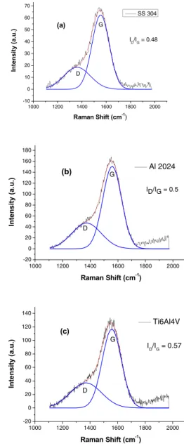
FIG. 4: Typical Raman spectra of DLC films prepared on SS 304 (a), Al2024 (b) and Ti6Al4V (c)
morphology. Typical Raman spectra of the films deposited on samples of SS 304, Al 2024 and Ti6Al4V, are shown in figures 4a-4c, respectively. The spectral profile was fitted by two Gaussian curves centered at 1360 cm−1, corresponding to the disordered peakD, and centered at 1550 cm−1, corre-sponding to the graphite-like peakG. Integral intensityID/IG
ratios were calculated from the ratio of the area of D peak and G peak, which signifies the sp3/sp2 ratio in the films. Slightly variation ofID/IGratios were obtained for DLC films
deposited on the surfaces of substrates of SS 304, Al 2024 and Ti6Al4V.
Corrosion resistance was evaluated for treated samples of SS 304 in comparison with untreated one. Figure 5 shows that nobler potentials were reached for the treated samples, besides an increase of the extension of the passive region, with lower current densities. This is a clear indication that the treated surfaces of SS 304 had improved corrosion resis-tance than their untreated counterpart. The improved corro-sion properties were obtained for the combined DLC implan-tation and coating, performed in stages of 30 and 60 min (case 1), respectively, and in four stages of 20 min each (case 2).
1E-10 1E-9 1E-8 1E-7 1E-6 1E-5 1E-4 1E-3 0,01 0,1 1 -0,6
-0,5 -0,4 -0,3 -0,2 -0,1 0,0 0,1 0,2 0,3 0,4 0,5 0,6 0,7
P
o
te
n
ti
a
l
(m
VA
g
/A
g
C
l
)
Current Density (A/cm2
)
untreated AISI 304 3IPD (20imp+20dep+20imp+20dep) 3IPD (30imp+60dep)
untreated 3IP&D
(30+60) 3IP&D (20+20+20+20)
FIG. 5: Measurements of the thickness versus compressive stress for Si samples treated by PIII + DLC coating, for 6 distinct conditions of operation
In order to study tribological properties of the DLC film, it was used a pin-on-disc type apparatus in the atmospheric en-vironment. Lower values of friction coefficient were obtained for treated SS 304 sample during 30 min of PIII + 60 min of pure coating, during all of the test period, but more pro-nounceable difference occurred in the beginning. This time, the friction coefficient of the sample treated in stages of 20 min of implantation/deposition had the same profile and sim-ilar friction coefficient values than the untreated counterpart, as can be seen in figure 6.
Roughness of DLC films deposited on the surface of silicon samples was measured by AFM. Estimated RMS roughness (Ra) for an untreated specimen was of 3.4 nm. In contrast, Ra = 8.44nm for case 1 and Ra = 6.07 nm for case 2, as can be seen in figures 7a and 7b, respectively. Smoother surface in this case was in favor of the sample treated in stages of 20 minutes. Film thickness was about 200 nm and deposition rate was around 130 nm/h for both cases.
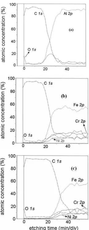
XPS analysis of the surfaces of aluminum alloy and stain-less steel treated according case 2 revealed the existing of carbon-rich layer at the top surface. For both substrates, car-bon concentration is above 93% for up to 20 min of etching
0 2000 4000 6000 8000 10000 0,0
0,2 0,4 0,6 0,8
F
ri
c
ti
o
n
c
o
e
ff
ic
ie
n
t
Laps
Standard AISI 304 3IPD [2x(20imp+20dep)] 3IPD (30imp+60dep) Standard
3IPD [2x(20imp+20dep)]
3IPD (30imp+60dep)
FIG. 6: Friction coefficient curves for treated and untreated samples of SS 304
FIG. 7: AFM image of Si sample treated during: (a) 30 min of PIII and 60 min of DLC coating, (b) 4 intercalated stages of 20 minutes of PIII and pure DLC coating.
time, as can be seen in figures 8a and 8b, respectively. Figure 8c shows the XPS measurement for SS 304 sample treated during 30 minutes under PIII and remaining 60 minutes with pure DLC coating. For this case the carbon concentration re-mained high up to 30 minutes of etching time; this represents an increase of 50% of the film thickness in comparison with the SS sample treated during 4 intercalated stages of 20 min-utes of PIII and pure DLC coating (figure 8b).
FIG. 8: XPS measurement for samples implanted/deposited with DLC: (a) Al 2024, (b) SS 304 (case 2) , (c) SS 304 (case 1).
IV. SUMMARY
Measurements with double Langmuir probe were effective to help to set a convenient window of operation for the mag-netron sputtering system.
The process of plasma immersion ion implantation com-bined with DLC deposition showed to be possible to control the thickness and the stress of the grow DLC film, by switch-ing conditions of the ion implantation and parameters of DLC coating. Also, even when the stress remained high (more than 10 GPa), probably the thin interface layer formed by the ion bombardment was able to anchor the very large compressive stress. This is an important issue because it opens possibili-ties to the growth of thicker films without delamination.
Ion bombardment previously to DLC deposition allowed the growth of DLC film in metals without the need of a sili-con interface. Very probably, the ion bombardment created a mixing layer which was essential to the DLC growth. Even though DLC films can grow on metal surfaces without the need of an interface when PIII is used, it seems that it is bet-ter to perform PIII previous to the DLC deposition in a single event, than to intercalate both processes, as it was verified in a comparison between cases 1 and 2. Besides the lower stress level in favor of case 1, high carbon concentration on the top surfaces of the samples treated according to case 1 was found for longer etching time, as shown by XPS analysis.
Improved properties of friction coefficient and cor-rosion resistance were observed for stainless steel im-planted/deposited with DLC. Further tests must be performed with the other metallic alloys to verify the extension of the benefit of DLC deposition for such cases.
Detailed sweep of the conditions of operation of this com-bined process must be performed, in order to better under-stand the mechanisms and effects of the ion deposition over the DLC deposition.
[1] Y. Lifshitz, G.D. Lempert, E. Grossman, Phys. Rev. Lett.72 (1994) 2753.
[2] J. Schwan, S. Ulrich, H. Roth,J. Appl. Phys.79 (1996) 1416. [3] A. Voevodin, M.S. Donley, J.S. Zabinski,Surf. Coating
Tech-nol.52 (1997) 42.
[4] M.M.M. Bilek, D. McKenzie, D.G. McCulloch, H. Zreiqat,J.
Appl. Phys. 87 (9) (2000) 4198.
[5] M. Noda, M. Umeno,Diamond & Related Materials14 (2005) 1791–1794.
[6] S.H.N. Lin, D.G. McCulloch, M.M.M. Bilek, D.R. McKenzie,
Surf. and Coat. Tech.174-175 (2003) 76.
[7] H. Dimigen, H. Hubsch, R. Memming,Appl. Phys. Lett.50 (1997) 1056.
[8] M. Chhowalla, Y. Yin, G.A. J. Amaratunga,Appl. Phys. Lett.
69 (1996) 2344.
[9] J. Meneve, E. Dekempeneer, W. Wagner, J. Smeets,Surf. Coat.
Tech.86 (1996) 617.
[10] A. Grill,Diamond and Related Materials12 (2003) 166. [11] Y. Liu, E. I. Meletis,Surf. Coat. Tech.153 (2002) 178. [12] V.M. Tiainen,Diamond and Related Materials10 (2001) 153. [13] J. Brand, R. Gadow, A. Killinger,Surf. Coat. Tech.180-181
[14] K. Okuri, T. Arai,Surf. Coat. Tech.47 (1991) 710.
[15] K.L.Choy, E. Felix,Materials Science and Engineering A278 (2000) 162.
[16] R.F. Huang, C.Y. Chan et al.,Diamond and Related Materials
10 (2001) 1850.
[17] J.P. Sullivan, T.A. Friedmann, A.G. Baca,J. Electron, Mater.
26 (1997) 1021.
[18] A.C. Ferrari, B. Kleinsorge, N. A. Morrison, A. Hart,J. Appl.
Phys.85 ( 1999) 7191.
[19] A. Anders,Surf. Coat. Tech.93 (1997) 157.
[20] S.H.N. Lim, D. G. McCulloch, et al.,Nucl. Instr. Meth. Phys.
Res. B.190 (2002) 723.
[21] J.O. Rossi, M. Ueda, J. J. Barroso,Braz. Journal of Phys., 34 4B (2004) 1565.