OPTIMAL DESIGN OF AN IP/MPLS OVER DWDM NETWORK
Eduardo Canale
1, Claudio Risso
2*and Franco Robledo
2 Received February 28, 2013 / Accepted October 21, 2013ABSTRACT.Different approaches for deploying resilient optical networks of low cost constitute a tradi-tional group of NP-Hard problems that have been widely studied. Most of them are based on the construc-tion of low cost networks that fulfill connectivity constraints. However, recent trends to virtualize optical networks over the legacy fiber infrastructure, modified the nature of network design problems and turned inappropriate many of these models and algorithms. In this paper we study a design problem arising from the deployment of an IP/MPLS network over an existing DWDM infrastructure. Besides cost and resiliency, this problem integrates traffic and capacity constraints. We present: an integer programming formulation for the problem, theoretical results, and describe how several metaheuristics were applied in order to find good quality solutions, for a real application case of a telecommunications company.
Keywords: telecommunications network, multi-layer network design, metaheuristics.
1 INTRODUCTION
In this paper, we address the problem of finding the optimal – minimum cost – configuration of a logical topology over a fixed optical network. The input data-set is constituted by the optical layer topology – DWDM network –, the client nodes of the data network – IP/MPLS nodes – and the potential links between them, as well as the data traffic demands to satisfy between each pair of nodes and the per-distance-cost in the optical network associated with the bitrates of the optical connections to deploy over it. The decision variables are: what data links do we have to implement, which bitrate must be assigned to each of them and what path do their optical implementations have to follow in the optical layer. For being a feasible solution a configuration must be capable of routing every traffic demand over the remaining active links of the data layer, for every single physical link failure.
Because of the changes in the technology this model is significantly different from former models – referred in next section –, so are the algorithms to find solutions.
*Corresponding author
We proved this problem is NP-Hard (Theorem 4.1) and due to its complexity we developed sev-eral metaheuristics to find good quality solutions for real size scenarios. Best results were found with GRASP. To achieve good performance, many theoretical results needed to be integrated during the design process of the algorithms.
A remarkable feature of this work is that we analyzed the performance of the proposed meta-heuristics using real-world scenarios provided by the Uruguayan national telecommunications company (ANTEL).
The main contributions of this article are:
i) a model to represent a common network overlay design problem;
ii) theoretical results useful to find and discard solutions under certain hypotheses;
iii) the design of a GRASP metaheuristic suitable to find good quality solutions;
iv) the experimental evaluation based on real-world network scenarios.
This paper is organized as follows. A history perspective is given in Section 2. A mixed-integer programming model will be presented in Section 3. In Section 4 we analyze the intrinsic com-plexity of the problem and some theoretical results useful to construct exact solutions for simple but important cases. In Section 5 we describe a real-world application case with many scenarios, present a battery of metaheuristics used to find good quality solutions, benchmark and analyze their results. Finally, in Section 6 we analyze the most important results of this work.
2 HISTORIC PERSPECTIVE
Some decades ago the increasing importance of the telephony service pushed most telecom-munications companies (TELCOs) to deploy optical fiber networks. In order to guarantee ap-propriate service availability, these networks were designed in such a way that several inde-pendent paths were available between each pair of nodes, and in order to optimize these large capital investments several models and algorithms were developed. Already the optimal de-sign of a single layer network is a challenging task that has been considered by many research groups, see for instance [6, 9, 18]. Throughout this work this optical network is referred to as thephysical layer.
the physical layer. DWDM supports a set of standard high-capacity interfaces (e.g. 1, 2.5, 10 or 40 Gbps). The cost of a connection also depends of the capacity but not proportionally. For economies of scale reasons, the higher the bitrate the lower the per-bandwidth-cost. The client nodes together with these lightpath connections form a so-calledlogical layeron top of the physical one.
The increasing number of per-physical-link connections – intrinsic to DWDM – may cause mul-tiple logical link failures from a single physical link failure (e.g., fiber cut). This issue led to the development of new multi-layer models aware of the stack of network layers. Most of these models share in common the 1+1 protection mechanism, i.e., for every demand two physi-cally independent logical paths must be provided, such that in case of any single physical link – or even node – failure, at least one of them survives. The following references [7, 10] are good examples of this kind of models. These multi-layer models are suitable for certain families of logical layer technologies such as synchronous optical networking (SONET) or synchronous digital hierarchy (SDH) since both standards have 1+1 protection as their native protection mechanism. As in these models, in our case, we assume that the physical layer is already installed and cannot be changed.
During many years the connections of IP networks were implemented over SONET/SDH – for simplicity we will only mention SDH from now on –. As a consequence, the IP layer – the third and top layer of this stack – rarely suffered unplanned topology changes. Most recently, mul-tiprotocol label switching (MPLS), traffic engineering extensions for dynamic routing protocols (e.g. OSPF-TE, ISIS-TE), fast reroute algorithms (FRR) and other new features were added to the traditional IP routers. This newtechnology bundleknown as IP/MPLS, opens a competitive alternative against traditional protection mechanisms based on SDH.
Since IP/MPLS allows recovering from a failure in about 50ms, capital savings may come from the elimination of the intermediate SDH layer. Another improvement of this technology is that the number of paths to route demands between nodes is not pre-bounded; so it might exist in fact a different feasible configuration for most failure scenarios. Moreover, there is no need to pre-establish all of these paths explicitly. If the appropriate information is fed to the routing protocols and the network is designed with care, the dynamic routing algorithms usually construct solutions of very good quality. Since IP/MPLS allows the elimination of an intermediate layer, manages Internet traffic natively, and makes possible a much easier and cheaper operation for virtual private network (VPN) services, it is gaining relative importance every day.
We refer to this problem as MORNDP (Multi-Overlay Resilient Network Design Problem). Solving the MORNDP implies:
i) design the data network, by defining the links to be include in the logical layer and the capacity assigned to each one;
ii) determine the lightpathfor each link in the data network; these paths are fixed, so every physical link failure propagates to all logical links that use it;
iii) provide the data network tolerance to single failures on the transport network, by de-termining paths for the IP/MPLS tunnels, one per-each physical failure, so when a fault arises, the network can route all traffic demands without violating the capacities of the logical links;
iv) minimizethe cost of the designed data network.
3 MATHEMATICAL MODEL
We will now introduce the basic mixed-integer programming model that arises from the detailed interaction of technologies.
Parameters.The physical network is represented by an undirected graph(V,P), and the logical network is represented by another undirected graph(V,L). Both layers share the same set of nodes. The links of the logical layer are potential – admissible logical links – while the links of the physical layer are definite. In both graphs the edges are simple since multigraphs are not allowed in this model.
For every different pair of nodes p,q ∈ V is known the traffic volumedpqto fulfill along the
unique path (tunnel) this traffic follows throughout a logical layer configuration. These paths are unique at every moment, but in case of link failures they may change to follow an alternate route. For simplicity we assume that the traffic volume is symmetric (i.e.dpq=dq p).
LetBˆ = {b1, . . . ,bB¯}be the set of possible bitrate capacities for the lightpaths on the physical layer and therefore for the links of the logical one. Every capacity b ∈ ˆB has a known per-distance costcb. For economies of scale reasons it holds that if
b′<b′′ then (cb′/b′) > (cb′′/b′′).
Since both graphs of this model are simple and undirected, we will express links as pairs of nodes. For every physical link(i j)is known its lengthli j.
Variables. This model comprises three classes of variables. The first class is composed of the logical link capacity variables. We will use boolean variablesτpqb to indicate whether or not the logical link(pq)∈Lhas been assigned with the capacityb∈ ˆB. As a consequence the capacity of the logical link(pq)could be computed as
b∈ ˆBb·τ b pq.
The second class of variables determines how are going to be routed the logical links over the physical network. If
b∈ ˆBτ b
it is going to be used in the logical network and requires a lightpath in the physical one. yi jpq
is a boolean variable that indicates whether or not the physical link(i j)∈ P is being used to implement the lightpath of(pq).
Since lightpaths cannot automatically recover from a link failure, whenever a physical link(i j) fails all the logical links(pq)such that yi jpq=1 do fail as well. The only protection available in
this model is that of the logical layer. For demands being protected against single physical link failures, is necessary to have a feasible route through the remaining active logical links.
The third and final class of variables is that that determines how the IP/MPLS tunnels are going to be routed against any particular failure in a physical link.rs i jxpq is a boolean variable that
indicates whether the logical link(pq)∈ L is going to be used or not, to route traffic demand drs >0, under a faulty condition in the physical link(i j)∈P.
NOTE: To keep the nomenclature of the variables as easy as possible we always placed: logical links subindexes at bottom right position, physical links subindexes at top right position and demands subindexes at top left position.
Constraints.This problem comprises three groups of constraints. The first group of constraints establishes the rules that the routes of the lightpaths must follow to be feasible.
⎧ ⎪ ⎪ ⎪ ⎪ ⎪ ⎪ ⎪ ⎪ ⎪ ⎪ ⎪ ⎪ ⎪ ⎪ ⎪ ⎪ ⎪ ⎪ ⎪ ⎪ ⎪ ⎪ ⎪ ⎪ ⎨ ⎪ ⎪ ⎪ ⎪ ⎪ ⎪ ⎪ ⎪ ⎪ ⎪ ⎪ ⎪ ⎪ ⎪ ⎪ ⎪ ⎪ ⎪ ⎪ ⎪ ⎪ ⎪ ⎪ ⎪ ⎩
b∈ ˆB
τbpq≤1 ∀(pq)∈L. (i)
j/(p j)∈P
ypqp j =
b∈ ˆB
τpqb ∀(pq)∈L. (ii)
i/(iq)∈P
yiqpq=
b∈ ˆB
τbpq ∀(pq)∈L. (iii)
j/(i j)∈P
yi jpq=2θˆipq
∀(pq)∈L,∀i∈ V,
i = p,i =q. (iv)
yi jpq−ypqj i =0 ∀(pq)∈L,∀(i j)∈ P. (v)
τbpq, yi jpq,θˆipq∈ {0,1}
∀(pq)∈L,∀(i j)∈ P
∀b∈ ˆB,∀i∈V. (vi)
(1)
The meaning of constraints in group equation (1) is the following:(i)establishes that the number of capacities assigned to every logical link is at most 1 – it could be 0 if the link is not going to be used –.
The constraints(ii)and(iii) guarantee that if any particular link(pq) ∈ L was assigned with a capacity (
b∈ ˆBτ b
pq = 1) then there must exist one and only one outgoing – or incoming –
physical link used for its lightpath.
Finally(v) guarantees that the lightpaths go back and forth through the same path, while(vi) stands the integrity of the variables.
The second group of constraints establishes the rules that the routes of the IP/MPLS tunnels must follow in the logical layer.
The meaning of the constraints in equation (2) is similar to those of equation (1) except for(i). The inequalities in(i)were added to guarantee that whatever the faulty scenario is ((i j)∈ P), its associated routing configuration over the logical network keeps the aggregated traffic load below the link capacity for every data link(pq)∈L.
Constraints(ii)and(iii) from equation (1) and equation (2) are equivalent, except for the fact that in the latter the existence of a tunnel relies on the existence of demand and this is known in advance.
Another remarkable point is that equation (2) has as many possible routing scenarios as arcs in P, so the number of variables is much greater than those of equation (1).
Variablesrsµˆi jp are homologous toθˆpqi ; so are constraints from(iv)to(vi).
⎧ ⎪ ⎪ ⎪ ⎪ ⎪ ⎪ ⎪ ⎪ ⎪ ⎪ ⎪ ⎪ ⎪ ⎪ ⎪ ⎪ ⎪ ⎪ ⎪ ⎪ ⎪ ⎪ ⎪ ⎪ ⎪ ⎪ ⎨ ⎪ ⎪ ⎪ ⎪ ⎪ ⎪ ⎪ ⎪ ⎪ ⎪ ⎪ ⎪ ⎪ ⎪ ⎪ ⎪ ⎪ ⎪ ⎪ ⎪ ⎪ ⎪ ⎪ ⎪ ⎪ ⎪ ⎩
rs:dr s>0
drs·rs i jxpq≤
b∈ ˆB
b·τbpq ∀(pq)∈L,∀(i j)∈ P. (i)
q/(rq)∈L
x
rs i j
rq =1 ∀drs>0,∀(i j)∈P. (ii)
p/(ps)∈L
x
rs i j
ps=1 ∀drs>0,∀(i j)∈P. (iii)
q/(pq)∈L
x
rs i j
pq=2·rsµˆi jp
∀drs>0,∀(i j)∈P,
∀p∈V,p=r,p =s. (iv)
x
rs i j
pq−rs i jxq p=0
∀drs>0,∀(pq)∈ L,
∀(i j)∈ P. (v)
x
rs i j pq, µˆ
rs i j
p ∈ {0,1}
∀drs>0,∀(pq)∈ L,
∀(i j)∈ P,∀p∈V. (vi)
(2)
Before proceeding any further we must notice that equation (1) and equation (2) are not inde-pendent. Many logical links may not be available for routing after a physical link failure. Which logical links are in this condition, relies on how the lightpaths were routed in the physical layer.
Specifically, if some logical link(pq)uses a physical link(i j)for its lightpath implementation then this logical link cannot be used to route any tunnel under(i j)failure scenario.
x
rs i j
pq≤1−yi jpq ∀rs :drs >0, ∀(pq)∈L, ∀(i j)∈ P. (3)
The group of constraints equation (3) prevents from using(pq)to route any traffic (rs i jxpq =
Objective. The function to minimize is the sum of the cost of every logical link. According on what capacity was assigned to a logical link there is an associated per-distance-cost (cb),
and according on how the corresponding lightpath was routed over the physical layer it has an associated length (
(i j)∈Pli jy i j pq).
The product of both terms is the cost of a particular logical link and the sum of these products for all the logical links is the total cost of the solution. The direct arithmetic expression for the previous statement would be
(pq)∈L
b∈ ˆB
cbτbpq
(i j)∈P
li jyi jpq =
(pq)∈L,(i j)∈P,b∈ ˆB
cbli j·τpqb y i j pq.
Although straightforward, this approximation is inappropriate because is non-linear.
The subproblem equation (4) expresses the objective value with an equivalent linear expression. We used the real variableb i jηpqinstead ofτbpqy
i j
pqand added some extra constraints to guarantee
the consistency.
The consistency comes from the following observations. The result ofτbpqyi jpqis also a boolean
variable, and sinceb i jηpqis being multiplied by a positive constant in a minimization problem it
will take its lowest value whenever this is possible. This value would be zero because of con-straints(iii)of equation (4).
⎧ ⎪ ⎪ ⎪ ⎪ ⎪ ⎪ ⎪ ⎪ ⎪ ⎪ ⎪ ⎪ ⎨ ⎪ ⎪ ⎪ ⎪ ⎪ ⎪ ⎪ ⎪ ⎪ ⎪ ⎪ ⎪ ⎩ min
(pq)∈L
(i j)∈P b∈ ˆB
cbli j·b i jηpq (i)
η b i j
pq≥τpqb +y i j pq−1
∀(pq)∈L,∀(i j)∈P,
∀b ∈ ˆB. (ii)
η b i j
pq≥0
∀(pq)∈L,∀(i j)∈P,
∀b ∈ ˆB. (iii)
(4)
The only exception is when the values ofτpqb andyi jpqare both 1, in which case the value of η b i j
pq
should be 1 as well to keep consistency. This is guaranteed by constrain(ii)of equation (4).
The optimization problem resulting from merging equation (1), equation (2), equation (3) and equation (4), express the problem MORNDP through a MIP (Mixed Integer Programming) formulation.
4 COMPLEXITY AND EXACT SOLUTIONS
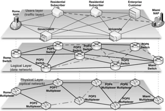
Figure 1–A three layers conceptual model.
Besides the formerly defined logical and physical layers, there is another abstract overlay on the top of them “the service perspective about the problem” or traffic layer, i.e., how are logical paths arranged to fulfill point-to-point demands between nodes (Figure 1).
Traffic volume is a primary component of the input data-set, which impacts deeply in the shape of the result.
4.1 Complexity
Since in this problem the traffic between nodes cannot be split into more than one path, the task of arranging tunnels over the logical layer is a remarkable subtask, closely related to – and basically as hard as – Integer Knapsack or Number Partition Problem (NPP). These are both well known NP-Complete problems. Hence, the shape of the traffic layer directly impacts in the complexity of the problem instance.
In [15], the NP-Completeness of the problem MORNDP was based on the interaction between traffic and logical layers. That is, the mere routing of the IP/MPLS tunnels over the Data Net-work – even without considering faulty physical links – is NP-Hard. The proof into the referenced article is based on a polynomial reduction of NPP to MORNDP.
In this article we present an alternate proof based on the interaction between logical and physical layers. This complementary proof has the extra value to show that the mathematical program detailed in Section 3 (MORNDP) is indeed the composition of solely very hard to solve problems.
Proof. Proof lies under reduction of the 2ECSS problem (Two-Edge-Connected Spanning Subgraph) to our particular problem that we will refer to as MORNDP (Multi-Overlay Resilient Network Design Problem). The 2ECSS problem consists in finding a minimum-weight subgraph of a weighted graph, in which every pair of vertices is two-edge-connected. The 2ECSS problem is a very well known NP-Hard problem (see for instance [2]).
We will use decision versions of both problems to validate instances. Letπk be the decision
problem consisting in saying whether it exists a feasible solution for MORNDP of costk, so that for everyk′<kthe answer toπk′ is negative.
Analogously, let πk′ be the decision problem consisting in saying whether it exists a feasible solution for the 2ECSS problem of costk, so that there is not other solution of lower weight.
(⇒)Given an instance G = (V,E,W)of the 2ECSS problem – for simplicity we will as-sume that all the weights are positive integers – we create an instance of MORNDP by tak-ing Bˆ = {N(N−1)/2},N = |V|, logical and physical graphs with the same topology ofG, li j =wi j∀(i j)∈ P(weights ofGarcs) anddi j =1,∀1≤i < j ≤ N.cb =1 for the unique
available capacity.
If the given instance satisfies the decision problemπk′, is because there existsG′⊆Gof weight kso thatG′is two-edge-connected and there is not other solution of lower weight.
The rules to construct a solution forπkfromG′are the following:
1. Take every edge ofG′and dimension its homologous logical link with capacityb1.
2. The remaining logical links will not be used.
3. Implement every effective logical link using its associated physical link.
It is immediate that the cost of the previous solution isk. Complementarily, logical link failures are one-to-one with physical link ones and therefore single physical failures affect at most one logical link. Due to the fact that logical layer copies the topology ofG′, the logical layer remains connected against any single physical link failure.
Finally, the capacity used in the logical links guarantees that none can be saturated. Hence, due to the fact that the construction mechanism turns connectivity into feasibility, the solution proposed forπkis feasible.
It suffices to observe that it cannot exist another feasible solution forπk of lower cost, because
that would imply that it also exists a lower cost solution forπk′. The formal arguments are basi-cally the same ones used in the following part of the proof.
(⇐)First, we claim thatgiven any solution to a positive instance ofπk constructed by the
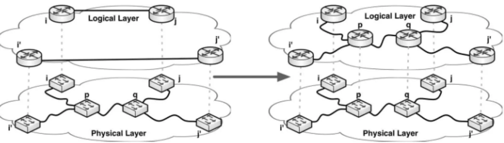
Figure 2–Non-disjoint lightpaths implementation and an alternate configuration.
If during the transformation we found that one of the new logical links is already present, we just skip this particular appending.
The transformation preserves – may even surpass – the logical connectivity in every failure sce-nario. It is also cheaper because the physical links between p andq are only used once in this solution. The last feature cannot hold because it would exist a solution whose cost is lower than k, which is explicitly forbidden in this decision problem. This ends the proof of our claim.
As a corollary of the previous property, we can prove thatgiven any solution to a positive instance ofπkis always possible to build an equivalent one where topologies of logical and physical layers
match. The transformation process is based on the following recurrence:
1. If any effective logical link is not implemented using its corresponding physical link, we must replace it with the logical links associated to the links of the lightpath.
2. If during the previous step a logical link is repeated, the former is replaced by the logical links associated to the links of its lightpath. This can always be done because implemen-tations must be disjoint.
3. Repeat the process until logical and physical networks match.
Since this transformation preserves the usage of links in the physical network, the cost of the solution and the failure scenarios are not affected.
Remains to be seen that the topology found (G′ =(V,E′)) is Two-Edge-Connected, so it is also a solution toπk′. Certainly, whenever a physical linkl ∈E′fails the remaining operational links of the logical layer (E′\{l}) must be capable of delivering the traffic. But since there is traffic demand between each pair of nodes, this is equivalent to state that∀l ∈ E′,G′\{l}is connected, so it is immediate thatG′⊆Gis a two-edge-connected graph.
Finally, it cannot exist another feasible solution toπk′ of costk′<k, because the outcome of the transformation described in(⇒)to this solution would be a feasible solution toπkof cost lower
thank. Let us keep in mind that the construction process turn connectivity into feasibility.
Since all the transformation are of a polynomial complexity it stands thatπk′ πk, and due to
Although finding optimal solutions to this problem is usually very hard to accomplish, discarding them may be much easier. The followingnecessary conditionproved to be a very useful tool for that.
4.2 Bonds and necessary condition
A “bond” is a well-known part of the graph theory glossary. It is called so to any minimal (but not necessarily minimum), proper, not empty set of edges whose removal disconnects the graph, splitting it into two components. We will extend this definition to our problem:
Definition 4.2.Let MORNDP be the problem presented in Section 3. Any bondP(regular bond
of the physical layer), will also be called a “bond of MORNDP” when: being (V′,P′) and (V′′,P′′)the two connected components of (V,P)\bondP, it holds that: (V′,LV′2) and (V′′,L
V′′2)are both connected components too. For simplicity we will refer to L
V′2and
L
V′′2as: L′and L′′respectively.
We will also define bondL,P = {e∈ L/e= pq,p ∈V′,q ∈ V′′}, which is actually a regular
bond of(V,L)induced by bondP.
The following property proved to be very useful during our algorithm implementation because it stands a very simple way to discard solutions.
Lemma 4.3. Let MORNDP be a problem as presented in Section 3. Given any solution to this problem, letL¯ ⊆L be the subset of arcs assigned with positive capacities. In order to be feasible, this solution must satisfy the following condition for every possible bondP:
p∈V′,q∈V′′
dpq≤bB¯ |bond
¯
L,P|(|bondP| −1)
|bondP|
(5)
Proof. The proof is based on a particular case of the “Pigeonhole Principle”. This is because regardless of how links inbondL¯,Pare implemented over the physical layer, they must use some
link ofbondP to connect(V′,P′)with(V′′,P′′). Then, there must exist at least one physical
edgee∈bondP, used at least|bondL¯,P|/|bondP|times by lightpaths ofbondL¯,P(Pigeonhole
Principle).
As a consequence, if the physical linkefails, the remaining capacity to route traffic from(V′,L′) to(V′′,L′′), falls down to at mostbB¯(|bondL¯,P| −
|bondL¯,P|/|bondP|
). If this capacity is below traffic demand between components (
p∈V′,q∈V′′dpq) the logical network cannot satisfy
demands. The previous condition it is numerically equivalent to state that if
p∈V′,q∈V′′
dpq >bB¯ |bond
¯
L,P|(|bondP| −1)
|bondP|
there is always an edgee ∈bondP, used so many times, that its fault leaves the resultant
oper-ational data network without enough capacity inbondL¯,P to route traffic between nodes ofV′
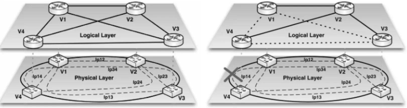
It is worth mentioning that the previous property is a generalization of the method given in [9]. For instance, in Figure 3 whenbB¯ =1 Gbps, the best bandwidth scenario between components is that where all links are assigned with 1 Gbps (i.e.: L¯ =L).
Figure 3–Extended version of Bonds to problem MORNDP.
But|bondL,P| = 5 and|bondP| = 3, so necessarily one link ofbondP must be used at least
twice to implementbondL,Plightpaths. If this link fails, the remaining capacity between(V′,L′)
and(V′′,L′′)falls to at most 3 Gbps. If aggregated traffic requirements between components were above this value, the solution could not be feasible.
The condition is not sufficient as we show below.
4.2.1 Counterexample to the bond condition
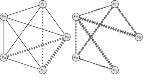
Consider the following problem: V = {v1, v2, v3, v4}, P = L = {(v1v2), (v2v3), (v3v4),
(v4v1), (v1v3)},Bˆ = {1}andd13=d24=1. Physical and Logical topologies are represented in the left side of Figure 4, while the second half sketches the traffic demands.
v1 v2
v3
v4
v1 v2
v3
v4
Figure 4–Counterexample to bonds conditions.
Because of symmetry,({v1},{v2v3v4}),({v2},{v1v3v4})and({v1v2},{v3v4})comprise the rep-resentative failing scenarios for bonds. Let us start by checking out that equation (5) is satisfied for these scenarios:
1) 1≤1
3(3−1) 3
=2; 2) 1≤1
2(2−1) 2
=1, 3) 2≤1
3(3−1) 3
The bond condition is always satisfied.
Suppose that some candidate solution is given for this instance. Regardless of how lightpaths are implemented, there must be some physical link whose fault affects logical linkv1v3lowering down the operational logical layer to at mostC4. Since traffic fromv1tov3 and fromv2tov4
must cross each other into some link and Bˆ = {1}, the reduced logical networks cannot satisfy the demands.
This condition assists the analysis of candidate solutions but stronger results were needed to construct the solutions themselves.
4.3 Exact solutions
Because of the complexity of the problem it is not expectable to find analytic solutions for the general case. Despite that, the analysis of particular cases was a key factor since many practical results were obtained from it.
Planarity is a common characteristic to most optical fiber networks, because most of them are deployed over earth’s surface.
Due to the fact that most physical networks can be decomposed intofaces, we aimed to find analytic solutions for this case as a foundation, over which construct feasible solutions. The following results correspond to limit cases of this kind of structure.
Theorem 4.4. GivenKn(clique) and Cn (cycle) respectively as logical and physical layers,
and if demands conform to dpq ≤ D, is always possible to find minimal feasible solutions for
MORNDP when bB¯ =2D and n is odd, or when bB¯ =3D and n is even.
Moreover, the solution when dpq = D and n is odd requires the usage of all the links ofKn,
whereas if n is even only diagonal links can be discarded, except for n=4.
Proof. This proof has several steps. First of all let us observe thatdpq = D is the hardest
demand case, so proving that ifdpq = Dandnis odd, the entireKn with links dimensioned
with a capacity 2Dis an optimal solution for the logical layer, would be enough for the feasibility (ifdpq <D) and the optimality (whendpq =D) for the odd case. Analogously, forneven we
will prove thatKnminus diagonals links, dimensioned with a capacity 3Dis optimal.
The next part of the proof consists in determining lower bounds for the capacity bB¯ and the number of logical links to implement whendpq = D. After that we will show how to construct
a feasible solution using that bounds. The minimal nature of that construction will close the optimality of the solution.
inequality turns toD(n−1)≤bB¯(n−1)/2 andbB¯must satisfybB¯ ≥2Din order to guarantee
the existence of solutions.
On the other hand, ifn is even the inequality turns toD(n −1) ≤ bB¯(n−2)/2 andbB¯ must
satisfybB¯ ≥2D(n−1)/(n−2). Since traffic between each pair of nodes isDand our problem does not allow to split this traffic through more than one path (tunnel), the capacity of any logical link has to be an integer multiple of Dto be useful. In other words, none of the tunnels can fit within a fraction of D. The first integer multiple ofDgreater or equal to 2D(n−1)/(n−2)is 3D, so practical solutions actually require thatbB¯ ≥3D.
It is time now to prove that those boundaries allow building feasible solutions. Ifn = 3 then
Kn matchesCn links of both layers one-to-one. Hence, whenever a link fails, the only way to
deliver traffic is through the link with the remaining logical neighbor, and capacity 2Dis enough for that.
The casen =4 is slightly tricky. The first half of Figure 5 shows the best choice for the path of each lightpath. The failure scenarios that affect most links are(v1v4)and(v2v3), reducing the logical layer to what is sketched in the second half of Figure 5.
Figure 5–Optimal solution found forK4overC4, withdpq= DandB= {3D}.
For this path configuration and ifbB¯ =3Dthe solution is feasible too. Actually, this configura-tion was found with CPLEX as the optimal soluconfigura-tion for the set of parameters.
For values ofngreater than 4 a more general rule must be used. Let us suppose thatn >4 and odd, son = 2k+1. The proposed implementation uses all of the logical links (Kn) and the
shortest number of physical hops to implement the lightpath of each one. Since n is odd this implementation is unique for each lightpath.
To route traffic between nodes in the non-faulty state, the direct route may be used – all nodes are neighbors –. For simplicity we will assume that nodes are numbered like(v0, . . . , v2k). Due to
the fact thatCnandKnhave cyclic symmetry, we can analyze a particular failure without loss of
generality. Let(v0v2k)be the physical link in faulty state. This fault condition affects all logical
links of the form(vi′vi′′)where:
i′ = 0,1, . . . ,k−1
i′′ ∈ {k+i′+1, . . . ,2k−1,2k}
On the first half of Figure 6 we represented an example of the effects of this fault over the logical layer, forn=5 (k=2).
v0
v1
v2
v3
v4
v0
v1
v2
v3
v4
Figure 6–Example case forn=5.
Dashed lines represent affected links. For those tunnels not affected by the fault, the direct logical route will be preserved. The surviving logical links still have a gap of capacity of magnitudeD, and we must find a way to deploy affected tunnels over them. The strategy is the following: take affected nodes in decreasing order of severity and attempt to detour all its affected tunnels in the minimum number of hops. This can be accomplished in 2 hops forv0– the most affected one – and in 3 hops for the remaining nodes.
The alternative route for those tunnels that followed a path of the form(v0vi′′)now turns to {(v0vi′′−k), (vi′′−k, vi′′)}, i′′ =k+1, . . . ,2k−1,2k. All the remaining faulty tunnels will be detoured in 3 hops according to the following rule: a faulty tunnel(vi′vi′′)will follow the path {(vi′vi′′−k), (vi′′−k, vi′′−i′), (vi′′−i′, vi′′)},i′′=k+i′+1, . . . ,2k−1,2k.
This new configuration is also sketched in Figure 6, where different kinds of dashed lines in the second diagram correspond to the route of the associated faulty tunnel.
To be sure this configuration is feasible, we must check that logical links are operational in this state and none is used more than once. Both are straightforward:
• Since all links are forward links with a number of hops less or equal thank, by construc-tion they cannot use(v0v2k)and must stand operational.
• The first logical link used to detour (v0vi′′)always starts at v0, while the second leap always haskhops. Since none of the links for the 3 leaps group has such length or origin, both sets cannot intersect.
• Within each set, logical links cannot be repeated by construction.
We used lower bounds to dimension logical links and wasted all of them, so this feasible solution is minimal and must be optimal, regardless of the lengths of the physical layer.
Unlike thenodd case, in this case, we opted for deleting diagonal links of the logical layer. This decision keeps unique the election of the lowest number of hops to implement lightpaths. The remaining aspects of the construction stay equal, except for some paths followed by the tunnels within the logical layer.
Since in the this construction we cannot use diagonals, the traffic betweenvi andvi+k (0 ≤
i ≤k−1) will be routed through{(vivi+k−1), (vi+k−1, vi+k)}, i =0, . . . ,k−1. This leaves a
remaining capacity of 2 or 3 in all of the logical links.
Instead of going into details of the construction of the tunnels within the logical layer in the representative fault state(v0v2k−1), we will present an illustrative workaround.
v0
v1
v2
v3
v4 v5
v0
v1
v2
v3
v4 v5
Figure 7–Example case forn=6.
Figure 7 outlines in its first half a diagram for the logical layer whenn=6, and represents with dashed lines the logical links affected by the failure of the physical link(v0v5). The second half of the picture details the operational logical links in this faulty state. If instead of this figure we look back to the second picture of Figure 6, we might conclude that both graphs look very similar. In fact, besidesv5they only differ in links(v3v5)and(v4v5). Moreover, in both cases demand betweenv0 andv4must be reestablished, but instead of demands betweenv0 andv3, and betweenv1andv4, in this case we have to figure out a solution to detour tunnels for pairs
(v0, v5)and(v1, v5). An easy workaround would be to use the former solution forn = 5 and adapt it to the new case. This can be achieved appending(v3v5)to the known tunnel betweenv0 andv3, and appending(v4v5)to the known tunnel betweenv0andv4. The previous ideas can be
easily generalized for anyk>6 and even.
Corollary 4.1.It is always possible to find minimal feasible solutions when:
1. The logical layer isKn;
2. The physical layer is a 2-edge-connected graph G (on the n vertices of the logical layer), such that each one of its kblocksis a cycle;
3. The demands conform to: dpq≤D;
Proof. First of all, let us notice that any graphGin the condition of2), is made up by identify-ingk−1 vertices from a cycle ofn+k−1 vertices. These vertex identifications originate the cut-vertices ofG.
An example instance of such G is represented on the right of Figure 8. A cycle, which can generate this instance after a selective identification process (marked with thin dashed lines), is sketched on the left half of the same figure. Within this proof, we refer to such a cycle with the list of identifications as anexpansionofG.
xx xx xx xx xx xx
x x x x x
x x x x x x
x x x x x
Figure 8–Example case forn=10,k=4.
It is tempting the idea of simply applying Theorem 4.4 over the expandedCn+k−1. However,
this cannot be done directly because nodes upon both layers do not match after expansion. In other terms only one on each set of identified physical nodes can have an associated logical node. This can nonetheless be fixed easily by contractingk−1 nodes. The first step consists in assigning – arbitrarily – the logical node corresponding to each expanded set to one of the physical nodes. The remainingk−1 logically unpaired nodes are recursively contracted with neighbors inCn+k−1until get toCn.
For instance in Figure 8 those nodes without a logical peer are marked with a white dot into the middle. Besides, in this example, those nodes selected for being contracted are shadowed with pale gray.
Once in this state we can apply Theorem 4.4 construction to determine capacities and routing configurations on both layers. To roll back this configuration overCn+k−1 we need to reinsert
those edges contracted that would be over the path. This is represented on Figure 8 using bold-dashed black curves.
Since edges ofCn+k−1 after identifying the corresponding vertices, are the same edges of G,
a failure in any edge ofGproduce the same effect than in the corresponding edge ofCn+k−1.
Therefore replicating paths over the logical layer following the per-scenario path configuration
of each LSP found for Lemma 4.4 works fine in this graph also.
Proposition 4.5. GivenCnas the physical layer and any logical layer L so thatCn ⊆L , if
de-mands conform to dpq≤ D it is always possible to find minimal feasible solutions to MORNDP
when bB¯ =Dn2/4and n is even, or if bB¯ =D(n2−1)/4and n is odd.
Moreover, the solution in both cases reduces to useCnas the logical layer.
Proof. The proof in this case relays on finding the most critical bond for the solution. Let us takeCn as the effective topology for the logical layer, where all links are dimensioned with
capacitybB¯. We will prove the feasibility for the hardest case (i.e.dpq =D).
If n is even we will take bondP = {(v1vn), (vn/2vn/2+1)}. This bond splits V into V′ = {v1, . . . , vn/2} and V′ = {vn/2+1, . . . , vn}. Let us observe that |bondP| = |bondL¯,P| = 2.
Applying Lemma 4.3 to this instance it gets that:
p∈V′,q∈V′′
D=
n/2
p=1
n
p=n/2+1
D=n 2
2
D≤bB¯
Ifn is odd we will takebondP = {(v1vn), (v(n−1)/2v(n+1)/2)}. This bond splitsV intoV′ = {v1, . . . , v(n−1)/2}andV′′ = {v(n+1)/2, . . . , vn}. Again in this case|bondP| = |bondL¯,P| =2,
but now Lemma 4.3 turns to
p∈V′,q∈V′′
D=
(n−1)/2
p=1
n
p=(n+1)/2
D=(n−1) 2
(n+1)
2 D=
(n2−1) 4 D≤bB¯
Givennwe will take the corresponding limits as the value forbB¯. Due to the low connectivity of this topology each logical link must to be implemented using its associated physical link, otherwise lightpaths would intercept in some physical link and the logical network would be disconnected by its fault.
We only need to check now that this implementation is feasible. Ifnis even and some physical link fails, the logical layer reduces to a sequence of connected nodes. Without loss of generality, the arcs of the logical layer could be {(v1v2), (v2v3), . . . , (vn−1vn)}. Given any of these arcs (vk, vk+1), 1≤k<n, the traffic across this link would be
k
1
n
k+1
D=k(n−k)D.
Ifnis even this function takes its maximum atn/2 which image isDn2/4, the value chosen to dimension links. Ifnis odd this function takes its maximum at(n−1)/2 and(n+1)/2 which image isD(n2−1)/4, and also matches the dimension of the logical link.
Intermediate cases are much harder to analyze. It is worth mentioning that our team used CPLEX to find solutions, but even over these trivial topologies we couldn’t find solutions forn ≥ 10 whendpqwas constant, or forn ≥15 whend1qwas constant anddpq=0, forall p,q, such that
5 A REAL-WORLD APPLICATION CASE
In order to find solutions for real applications we used metaheuristics, but before going any further we will present some aspects of the concrete problem of ANTEL.
5.1 Context and characteristics
Internet is actually a network disaggregated into several separate smaller networks also known as Autonomous Systems (AS). Typically, every AS is a portion of the global Internet owned/ governed by a particular Internet Service Provider (ISP). Network nodes and content servers of ISPs are geographically distributed over POPs (Point-of-Presence).
Internet users access content residing in servers of companies, universities, government sites or even from other residential customers (e.g. P2P applications). Most of these servers as well as servers ofContent Delivery Networks(CDN) – e.g. Google or Akamai – are installed into datacenters. Since traffic interchange is necessary among different ISPs, the Internet architecture needs special POPs known asNetwork Access Points(NAPs).
The previous high-level structure is shared among ISPs all over the world; additional details are proper to the design criteria established by each one. Regarding our application case, ANTEL had two different IP/MPLS networks referred to asaggregation networkandpublic Internet network. Theaggregation networkis geographically dispersed all over the country and it is responsible of gathering and delivering the traffic of the customers, to thepublic Internet network.
Thepublic Internet networkis where the AS of this ISP is implemented; it centralizes the inter-national connections with other ISPs as well as those to Datacenters of local content providers. The public Internet networkis geographically concentrated and only has POPs in the Capital City and in an important NAP of the US territory (see grey clouds in Figure 9).
Figure 9–Structure of the particular network architecture.
Several planning concerns arose from the situation exposed:
• Is the current architecture convenient? or Would it be better to merge both IP/MPLS net-works?
• Are the IT infrastructure investments necessary to increase the percentage of local content profitable?
• Which would be the optimal network to fulfill every demand requirement at lowest cost possible?
• How much is the sensitivity cost due to changes in demands?
To answer these questions we identified representative scenarios and used metaheuristics to find good quality solutions for them. Scenarios were selected varying the following factors: traffic volume, network architecture and the percentage of locally terminated traffic. We selected eight remarkable scenarios as detailed in Table 1. The costs and traffic information shown in the rest of this article are only referential.
According to the traffic forecasts, it is expected that in a few years, the total volume of traf-fic would be placed somewhere between 56 and 100 (reference values). Additionally, if some IT investments and agreements were made, it is expected that the percentage of locally termi-nated traffic (national traffic) could be greater (High). Both factor were considered to determine scenarios.
Table 1– Referential results for representative scenarios.
scenario aggregated % local merged number required total
index traffic demand content networks ofnodes lightpaths cost
1 100 Low False 56 81 10,000,000
2 100 Low True 68 133 7,662,651
3 100 High False 56 81 7,578,234
4 100 High True 68 118 5,713,563
5 57 Low False 56 75 6,319,470
6 57 Low True 63 105 4,872,987
7 57 High False 56 75 5,108,587
8 57 High True 63 94 4,064,597
Those scenarios wheremerged networksis set toFalseinherit the current network architecture – two separates IP/MPLS networks –, whereasTrueindicates that both networks – aggregation and public Internet – have been integrated into one. In order to compare solutions fairly, the column “total cost” represents the combined cost of both networks – when they are not combined into one –. However, column “required lightpaths” only considers those of the aggregation network.
5.2 Usage of Metaheuristics
Based on the scenarios detailed in Table 1, our team explored the implementation of heuristics and metaheuristics to find answers to the former questions. The main aspects and results for them are summarized next:
1. Two Stages Approximation –Instead of attempting to optimize the entire problem at once as described in Section 3, this approximation splits the problem into two non-independent stages. The first stage aims to construct of lightpaths for the logical links, whereas the sec-ond stage focus on capacity assignments and how traffic can be routed in failure scenarios.
CPLEX was used as the central optimization toolbox for this heuristic. Solutions could not be found for scenarios with merged networks (2,4,6 and 8 in Table 1). Even for the remaining scenarios, instances had to be reduced toeastandwestregions (see Figure 9) to find solutions.
For further information on this heuristic, see [12].
2. Genetic Algorithms –The application of sequential and parallel evolutionary algorithm to this problem showed promising results. To be practical, the model had to limit to two the number of logical routing configurations – whereas the original model allowed as many as fault scenarios –. Nevertheless, with this implementation, scenarios 3, 5 and 7 could be solved.
The best solution for scenario 3 was found with this algorithm, even though the search-space was smaller than those of the rest. For further information on the usage of this metaheuristic to the problem see [14].
3. Variable Neighborhood Search and Tabu Search –Unlike the previous examples, in this case both metaheuristics were used to optimize the problem as a whole – as described in Section 3 –. Solutions could only be found wheneastandwest regions were treated as isolated networks. Even so, results were useful because topology depicted in Figure 9 for scenarios with separates aggregation and Internet networks (indexes 1, 3, 5 and 7), allowed to optimize each region separately as a different traffic tributary to the capital city. For further information on the usage of this metaheuristic to the problem see [1].
4. Greedy Randomized Adaptive Search Procedure –According to our benchmarks, this implementation proved to be the most suitable to find solutions for instances summarized in Table 1. Indeed, this was the only algorithm that found solutions for all scenarios, and all the solutions but one in this table, were found with GRASP. Because of its outstanding behavior we will describe this algorithm in further detail.
All algorithms were able to find solutions (optimal solutions mostly), for instances like those used in of Theorem 4.4 and Proposition 4.5. This is because of the simplicity of the physical layer on both cases. The Two Stages Approximation and VNS algorithms, hardly found solutions on physical topologies other thanCn, even for networks with less than 20 logical nodes.
5.3 GRASP Implementation
The Greedy Randomized Adaptive Search Procedure (GRASP), is a metaheuristic successfully applied to construct good quality solutions for several combinatorial optimization problems of diverse areas, which range from clustering ([3, 17]) to network design problems ([16]).
As for every GRASP implementation this algorithm has a loop with two phases. Theconstruction phasebuilds arandomized feasible solution, from which a local minimum is found during the local search phase. This procedure is repeatedMax I t ertimes while the best overall solution is kept as the result. Further information and details in GRASP algorithms can be found in [11, 13].
initialization overlay
routing feasible?
selective
link removal feasible?
start/end MaxIter? untested
links?
undo link removal
yes
no no
yes yes
no yes
no
Local Search Randomized Feasible
Solution
Figure 10–Block-diagram of the GRASP implementation used.
Figure 10 outlines a block diagram of the GRASP implementation. On next subsections we analyze – phase by phase – the most relevant characteristics of this implementation. Many of them are based on the results presented in Section 4.
5.3.1 Input data-set and initialization
Because of strategical and economical matters, ANTEL decided to consider only 10 Gbps as a possible speed to assign to logical links. This allowed us to simplify a portion of the model described in Section 3.
Besides mandatory logical links, the remaining ones are included to meet constraints from Lemma 4.3, Theorem 4.4 and Proposition 4.5. For this purpose the faces of the plain repres-entation of the physical layer are analyzed one-by-one. To determine how many logical links should be included within each face, the following rules were used:
1. Preserve traffic demands between nodes of the same face.
2. Distribute uniformly traffic terminating in nodes outside of the current face, among nodes contained both, into the current and neighbor faces.
3. Set up logical links according to Theorem 4.4 and Proposition 4.5.
For instance, Figure 11 present an hypothetical case where thin-black lines represent physical links and thick-grey ones correspond to logical internal to faces. When considering{v1, v2, v3,
v4, v5}, if by exampled17 =3 then this demand is temporarily omitted and remaining demands are updated so:d12′ =d12+1,d13′ =d13+1 andd14′ =d14+1.
v3 v1
v6
v10
v11 v13
v9
v4
v12
v8
v2
v5
v7
Figure 11–Logical links internal to faces.
All internal links of the face delimited by{v1, v2, v3, v4, v5}were included because the number of nodes is odd and after computing new demands – step 2 of transformation –, some of them was close – above 60% – tobB¯/2. A similar situation arose for{v4, v3, v7, v10, v12, v13}, although in this case some demand was nearbB¯/3. Diagonals were omitted because last face has an even number of nodes, as states Theorem 4.4.
In the case of faces delimited by{v3, v2, v6, v7}and{v10, v11, v12}, demands were below 4bB¯/n2 and 4bB¯/(n2−1)respectively, corresponding to limits established in Proposition 4.5; then the cycle was used as the reference topology. The same situation arose for{v7, v6, v8, v9, v10}but the gap in this case was narrow. That issue, together with the fact that the number of neighbor faces for this case is above the average, led us to add an extra link (v6v10) to facilitate detouring of traffic through this face in failure scenarios.
several selected bonds, like for instance in Figure 12. In this case links are added until the gap between terms of equation (5) applied to the bond represented with a semi-dashed line, surpassed 50%. The process is repeated for several bonds.
v3
v1
v6
v10
v11 v13
v9
v4
v12
v8
v2
v5
v7
Figure 12–Logical links between faces.
Although possible, we did not intend to automatize the previous process. The truth is that doing it manually was not a hard task and it added the value to integrate intuitive decision together with network designers, taking advantage of their experience. This work was always stated as a tool to assist decisions, not as a substitute of designers.
5.3.2 Initializations
The initializationphase performs computations whose results are invariants among iterations. One of them is the shortest path and distance over the physical layer between each pair of nodes.
Finding a base for structural bones is another remarkable computation realized during this phase. We apply Lemma 4.3 to increase the construction speed, discarding candidate solutions with few computations. That, would be cheap if there was an easy way to generate cycles automatically, because it is a well-known graph theory property that: “bonds of a plain graph are those whose edges form a cycle in the dual graph” (see [19]).
Unfortunately, finding all cycles within a graph, even for a planar and cubic graph, is NP-Hard. The previous is direct from [4] where it was proved that decision problem: “to find out if a planar, cubic and 3-conex graph is Hamiltonian is an NP-Hard problem”.
Figure 13 shows how this idea applied to a hypothetical physical network (the left side part of the image), outcomes to a much more simple problem. The structural physical networks counts 8 nodes, whereas the original has 53. The second half of this picture also represents the dual graph, with one node per face {A,B,C,D,E,F}and one link between every pair of nodes whose associated faces are adjacent. The dual graph is usually a multi-graph.
Through this example example, it is easy to show how bonds are determined from cycles. For instance, there are three cycles that span nodes{A,C,D}. They are determined by the unique links between(A,C)and(C,D), combined with the three different links that connect(A,D). Each of these cycles defines a structural bond, specifically for these cycles they would correspond
to{PAY-SNR, ALG-YOU, PTO-CRC}, {PAY-SNR, ALG-YOU, FRB-MRC}and {PAY-SNR,
ALG-YOU, MAB-SJM}.
Figure 13–Structural bones defined by dual cycles.
5.3.3 Overlay routing
This block aims to build a feasible configuration of lightpaths over the physical layer. Prior to do this a subset of input logical links must be chosen to be part of the solution. In this stage of the construction the emphasis lies on determining which inter-faces logical links are necessary. This process is very simple, for every structural bond (as seen in Section 5.3.2) a subset of the logical links that traverse this bond is randomly chosen in order to minimally satisfy equation (5).
The second step of this block, consists in performing a heuristic to construct a balanced-routing configuration of low-cost for the remaining logical links.
used. A detailed explanation of the heuristic implementation used to find the configuration of the lightpaths, can be seen at [15].
Regarding performance, there is an important feature of our implementation: it is much cheaper to discard a solution than accept it as a feasible one. This is because to validate a candidate solution, a different configuration must be found to route traffic in every failure scenario, whereas to discard it, we take the result of the heuristic that will be commented in Section 5.3.4. This heuristic usually stops very quickly when there is not enough capacity in some failure scenario. So, prior to pass to thelocal searchphase, inter-faces links are reinserted selectively until regain feasibility.
5.3.4 Local search
In opposition to the strategy followed in the previous phase, in this one, we take each logical link of the solution – all of them, inter and intra-faces links – in decreasing order of cost – lightpaths costs – and attempt to remove it from the solution. If the result remains feasible, this link will be excluded from the solution; otherwise it will be reinserted. The process is repeated until all links are analyzed.
Although simple to express, the previous strategy lacks in performance if it is thoroughly applied. This is because the problem of finding an exact answer to the question: Is a given network able to route traffic under constraints of Section 3, is NP-Complete. Arguments regarding this fact were commented in the first part of Section 4.
Instead of an exact algorithm, our implementation used an efficient heuristic. Moreover, our heuristic is based on an improvement of the algorithm that commercial routers implement over IP/MPLS networks, for automatic routing with traffic engineering based on constraints. The basic algorithm is called Constrained Shortest Path First (CSPF), and our implementation improved the construction by sorting paths in decreasing order of traffic demand before routing.
This approximation integrates a well known heuristic used to solve NPP (Number Partition Prob-lem), which is an NP-Complete problem from which we proved that the mere optimal routing over the logical layer was NP-Hard. For further details on CSPF refer to [20] and for NPP refer to [5].
Although it is possible for this heuristic to discard feasible solutions, it is unlikely. Further details of the heuristic implementation is out of the scope of this paper, but it can be accessed at [15].
6 CONCLUSIONS
be done carefully. Because of the complexity of this problem, it is not expectable to find good quality solutions manually.
Without opening reserved details, we must comment that results for scenarios summarized in Table 1, helped ANTEL in several ways. First of all, there were cases where savings coming from computed solutions exceeded 30%. Moreover, manually designed networks suffered effects from physical faults more often and critically than solutions created using this metaheuristic. So the usage of this algorithm helped not only to save cost but also to improve the quality of the solutions.
For some aspects of design (questions of Section 5.1), it would have been impossible to have ac-curate answers without computer assistance. For example: allowing some changes to the current architecture, like merging both IP/MPLS networks into one, reported extraordinary improve-ments in the quality of the solutions. An extended analysis allowed us to isolate particular issues of the physical network responsible of these gaps. Many of these issues were fixed or are under process of correction.
We are confident that the context this work deals with is not an exception, and improvements should replicate from one ISP to the other. We are also confident that there is room to improve the quality of algorithms, by combining some of them into a hybrid. This is planned as future work.
Finally, we successfully integrated theoretical results during the design and implementation of some metaheuristics. GRASP was especially suitable to this, and we are confident that the out-standing results obtained with it, are based in the high level of tuning this metaheuristic allowed to introduce.
ACKNOWLEDGMENTS
The work of C. Risso, E. Canale and F. Robledo was partly supported by ANII and PEDECIBA, Uruguay. We also would like to thank to ANTEL (Administraci´on Nacional de Telecomuni-caciones from Uruguay) for its financial support to our work; and especially to: Diego Valle Lisboa and Laura Saldanha for helping us to define the models and gathering all the information necessary to feed and benchmark these algorithms.
REFERENCES
[1] COREZA & ROBLEDOF. 2011. Multi-overlay network planning by applying a Variable Neighbor-hood Search approach.Proceedings of IEEE 3rd Latin-American Conference on Communications 2011 (IEEE LATINCOM 2011), Bel´em do Par´a, Brazil. p. 1–6.
[2] ESWARANKP & TARJANRE. 1976. Augmentation problems. Society for Industrial and Applied Mathematics (SIAM).Lecture Notes in Mathematics,5(4): 653–665.
[4] GAREYMR & JOHNSONDS. 1979. Computers and Intractability: A Guide to the Theory of NP-Completeness. New York: W.H. Freeman. ISBN 0-7167-1045-5.
[5] HAYESB. 2002. The Easiest Hard Problem: Number Partitioning.American Scientist,90(2): 113, March-April 2002, New York, USA.
[6] KERIVIN H & MAHJOUBAR. 2003. Design of survivable networks: A survey.Networks,46(1): 1–21.
[7] KOSTERA, ORLOWSKIS, RAACKC, BAIERG & ENGELT. 2008. Single-layer Cuts for Multi-layer Network Design Problems.Springer-Verlag: Selected proceedings of the 9th INFORMS Telecommu-nications Conference,44(1): 1–23.
[8] OELLRICHM. 2008. Minimum Cost Disjoint Paths under Arc Dependence. Algorithms for Practice. PhD thesis: University of Technology, Berlin, Germany.
[9] OKAMURAH & SEYMOURPD. 1981. Multicommodity flows in planar graphs.Journal of Combi-natorial Theory, Series B,31(1): 75–81.
[10] ORLOWSKIS, KOSTERA, RAACKC & WESSALY¨ R. 2007. Two-layer network design by branch-and-cut featuring MIP-based heuristics.Proceedings of the 3rd International Network Optimization Conference (INOC 2007), Spa, Belgium.
[11] PARDALOS PM & RESENDE MGC. 2006 Handbook of Optimization in Telecommunication Springer Science + Business Media, New York. February 2006, ISBN: 0-38-730662-5.
[12] PARODIC. 2011 Integer Optimization Applied to the Design of Robust Minimum Cost Multi-Layer Networks. Master Thesis. Universidad de la Rep´ublica, Uruguay.http://premat.fing.edu. uy/IngenieriaMatematica/archivos/tesis_cecilia_parodi.pdf.
[13] RESENDEM & RIBERIOC. 2003. Greedy randomized adaptive search procedures. ATT Research. http://www2.research.att.com/˜mgcr/doc/sgrasp-hmetah.pdf.
[14] RISSOC, NESMACHNOWS & ROBLEDOF. 2012. A Parallel Evolutionary Algorithm for Multi-layered Robust Network Design. Selected proceedings of the 1st International Workshop on Soft Computing Techniques in Cluster and Grid Computing Systems (SCCG 2012), Victoria, Canada. p. 291–296.
[15] RISSOC & ROBLEDOF. 2013. Using GRASP for designing a layer network. International Journal of Metaheuristics, Special Issue on Metaheuristics for Security, Reliability and Trust (IJMHEUR 2013). To appear.
[16] ROBLEDO F. 2005. GRASP heuristics for Wide Area Network design. PhD thesis, Universit´e de Rennes 1, 2005.
[17] SILVAGCDA, OCHILS & MARTINSSL. 2006. Proposta e avaliac¸˜ao de heur´ısticas GRASP para o problema da diversidade m´axima.Pesquisa Operacional, Ago 2006,26(2): 321–360. Brazilian Operations Research Society. ISSN 0101-7438.
[18] STOERM. 1992. Design of survivable networks. Lecture Notes in Mathematics.
[19] WESTDB. 1995. Introduction to Graph Theory. Theorem 7.1.12. Prentice Hall Professional Tech-nical Reference, ISBN-13: 9780132278287.
[20] ZIEGELMANN M. 2007. Constrained Shortest Path and Related Problems. Constrained Network