Abstract
In order to reduce the structural vibrations of a mechanical system used in aerospace, a new sketch of eddy current damper (ECD), consisting of one cylindrical permanent magnet, two ring-shape copper plates, one axial transmission shaft and electromagnetic shield, is proposed. Three dimensional (3D) electromagnetic tran-sient analysis on damping performance of the proposed damper is conducted by ANSYS to determine the dimensions of the designed damper. And a series of damping tests for the damper subjected to sinusoid excitations with amplitudes of around 0.1 and 1 mm are respectively carried out under frequencies ranging from 1 to 50 Hz. The experimental results validate that the 3D transient analysis method with ANSYS is effective to guide the design of ECDs. Moreover, it is found that the proposed ECD has high damping, which is significantly superior to the one-plate ECD with the same structure and dimensions.
Keywords
Eddy current damper, damping, transient analysis, finite element method, aerospace.
Design and Damping Analysis of a New Eddy
Current Damper for Aerospace Applications
1 INTRODUCTION
The rapid development of aerospace technologies has led to a variety of applications like high reso-lution remote sensing, observation camera etc. These innovations are associated with some issues to be solved, involving structural vibrations induced by mechanical device in aircraft or planet (Wijker, 2004; Huo et al., 2012). To protect mechanical system from damage caused by vibrations, it is usual to isolate or attenuate such vibrations by utilizing damping devices. Since it is rather difficult to implement maintenance and the operational environment is severe in aerospace, the damping device should be advanced in long function fatigue life, high reliability, and good applicability in vacuum and heat transformation conditions. Eddy current dampers (ECDs), with instinct natures such as
Qiang Pan a Tian He a * Denghong Xiao a Xiandong Liu a
a School of Transportation Science and
Engineering, Beihang University, PR China
*Corresponding author:
http://dx.doi.org/10.1590/1679-78252272
non-contact, non-leakage and easy implementation, become a candidate to suppress vibrations of a system for aerospace applications (Sodano and Bae, 2004).
ECDs are based on the interaction between a non-magnetic conductive material and a time varying magnetic field in their relative motion. The eddy currents are generated either by move-ment of the conductive material through a stationary magnet or by strength or position change of the magnetic field source, and in turn induce a magnetic field with opposite polarity as the applied field and a repulsive electromotive force (EMF) which is dependent on the rate of change of the applied field. Due to the internal resistance of the conductive material, the induced currents are dissipated into heat and the energy transformed from the system is removed (Bae et al., 2005).
A number of studies related to eddy current damping mechanisms and its applications have been reported in the literatures. Schmid and Varaga (1992) devise a vibration attenuation system for the construction of high-resolution scanning tunneling microscope by using eddy current damp-ers. Their research indicate the two-stage spring-suspended systems with eddy-current damping for the upper stage only are superior to similar systems with eddy-current damping of both stages. So-dano et al. (2005, 2006) propose a type of ECD to suppress the transverse vibration of a beam structure and study its damping characteristics in both ambient and vacuum conditions. Based on electromagnetic theory and energy method, a theoretical model of the system is established to esti-mate the electromagnetic damping force generated from the structure and experiment is performed to verify the model. Their results show that the proposed ECD may provide sufficient damping force to quickly suppress the beam’s vibration. Kwag et al. (2007) and Bae et al. (2009) propose and develop an eddy current shock absorber by using a permanent magnet in a conductive tube and discuss it is more effective than Sodano’s model because the radial flux is almost perpendicular to the copper tube surface. Ebrahimi et al. (2008, 2010) design and analyze an eddy current passive damper with different configurations of permanent magnets. Its damping characteristics are ob-tained through analytical modeling and verified by experimental works. Cheah and Sodano (2011) develop a novel eddy current mechanism for passive magnetic bearing and carry out theoretical and finite element analysis to predict the force as it vibrates. Zuo et al. (2011) present a new designed eddy current damper for structural vibration control in civil engineering field. The magnetic field in this damper is split into multiple ones with alternating directions to reduce the electrical resistance of the eddy current loops and increase the damping force and damping coefficient. In addition, the dependence of damping on velocity and frequency is also examined in their paper.
expe-rienced during shuttle launch and aims to serving for 20 years without maintenance. In his research, the dynamic behavior of the ECD is analyzed and it is found that the force/velocity ratio of the damper significantly varies with temperature. Sodano and Bae (2004) review various types of eddy current damping mechanisms used in different structures and systems, including the applications utilized in space field. In addition, the future of eddy current dampers with some potential uses that have not yet been studied is discussed in his article.
Some numerical simulations on the magnetic field distribution and eddy current of ECDs are al-so conducted, generally based on finite element method (FEM). Many of them have been verified by experiments under given conditions. For example, Albertz et al. (1996) use a complete FE formula-tion for the calculaformula-tion of nonlinear eddy current fields with ferromagnetic moving conductors. The computation procedure is applied to an eddy current braking system of a high velocity train and the resulting braking forces are compared to measurements. Baranski et al. (2011) perform the transient electromagnetic finite element analysis of the eddy current damper for a last stage steam turbine blading and carry out parameter studies to calculate its equivalent damping factors. Laborenz et al. (2011) offer special software and elaborate its algorithm for transient finite element (FE) analysis of coupled electromagnetic-thermal problems in a squirrel cage induction motor. Bíró et al. (2014) provide an efficient finite element method to take account of the nonlinearity of the magnetic mate-rials when analyzing three-dimensional eddy current problems. It is shown that using FEM together with the continuous/discrete harmonic balance method is capable of providing the steady-state solu-tion to large, complex real-world eddy current problems when nonlinearity of ferromagnetic media is taken into account. However, most analysis on damping of ECDs is on basis of 2D steady method, by which 2D magnetic field can be obtained accurately but it is unable to analyze 3D magnetic field distribution and eddy current of ECD consisting of permanent magnets. Though 3D transient anal-ysis method is probable to solve such problems, rare research has been conducted so far.
In this paper, a damper based on eddy current damping mechanism is designed. The 3D elec-tromagnetic transient analysis on damping performance of ECDs consisting of one permanent mag-net is conducted by commercial package ANSYS to determine its structural parameters. In order to validate the damping performance of ECD resulting from numerical simulation, a series of experi-ments subjected to sinusoid excitation with amplitudes of around 0.1 and 1 mm are performed un-der frequencies ranging from 1 to 50 Hz.
2 CONFIGURATION OF ECD
One effective way to achieve high damping of an ECD is enhancing the variation of applicable magnetic fields. Aiming at this target, a new ECD design sketch based on Sodano’s model (2005) is proposed in present work, as shown in Figure 1.
flux through the upper copper plate increases and the lower one decreases simultaneously, and vice versa. However, both of them cause repulsive forces against their motions. The repulsive forces are proportional to the velocity of the shaft and, as it was descripted above, the damping work done during this process acts as dissipated energy. It is expected that the proposed ECD with two copper plates may generate large eddy current and damping force, resulting in better damping performance than one-plate ECD.
Figure 1: The schematic model of the magnetic field of proposed ECD.
Figure 2: Configuration of the proposed damper.
3 ELECTROMAGNETIC SIMULATIONS OF THE ECD
In order to achieve high damping, the geometry sizes of the ECD components are to be determined by performance analysis of the damper. Since the design based on experiments is too costly and time-consuming, it is feasible to utilize numerical simulation method to analyze performance of the damper initially. Hence 3D electromagnetic transient analysis on magnetic field of ECD is conduct-ed by ANSYS basconduct-ed on FEM in present work.
3.1 3 D Transient Electromagnetic Analysis
Har-monic analysis can be considered as quasi-static since its frequency may be assumed very small. Under such conditions, it is applicable to simulations in an invariable magnetic field only. In 3D transient analysis, the invariable magnetic field generated from permanent magnet is equivalent to some loading steps with respect to time, in which the magnetic field intensity increases with time until its maximum and keep constant forwards. It should be noted that in each loading step, not only the boundary conditions but also corresponding time and items related to loads are defined.
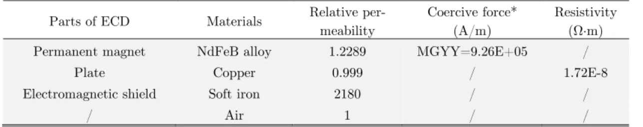
A detailed description on 3D transient electromagnetic analysis is given as follows. The material properties of the ECD in simulations are defined in Table 1. The element type using in simulations is SOLID97 of 8 nodes. The velocity effect of the eddy current plate is defined by conventional ve-locity Veloy=-0.1 m/s, where the negative sign means the eddy current plate moves downwards along the vertical direction. And the velocity effect of other parts of the ECD is not taken into ac-count. On the upper and lower surfaces of ECD, magnetic lines are parallel to the horizontal direc-tion. It is the boundary condition applied in the electromagnetic simuladirec-tion.
Parts of ECD Materials Relative
per-meability
Coercive force* (A/m)
Resistivity (Ω·m)
Permanent magnet NdFeB alloy 1.2289 MGYY=9.26E+05 /
Plate Copper 0.999 / 1.72E-8
Electromagnetic shield Soft iron 2180 / /
/ Air 1 / /
* Where MGYY represents the coercive force in vertical direction.
Table 1: Material properties of parts of ECD.
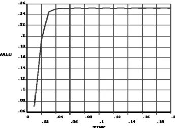
As it was mentioned above, the magnetic field generated from permanent magnet is equivalent to two loading steps in 3D transient analysis. Figure 3 plots the relation of the magnetic field versus time. In the first loading step, the magnetic field linearly changes with respect to time at 0-0.04 s. While in the second loading step, the magnetic field is invariable until 0.2 s and every substep is iterated a few times with time integration effect option turning on. The output of 3D electromag-netic transient analysis to the ECD includes strength and distribution of magelectromag-netic field, the eddy current and the Lorentz force. It should be noted that the accuracy of simulation results is highly dependent on the time step size defined in analysis. Though small size generally leads to high accu-racy of the analytical result, sometimes it is accompanied with a significant error if it is set too small, especially in the setting of initial conditions. Moreover, the 3D transient model will be vali-dated by conducting damping experiments to the prototype of ECDs in Section 4.
3.2 Determination of Structural Parameters
Figure 3: Magnetic field VS time in transient analysis.
Parameter Value
Diameter of magnet (mm) 52
Thickness of magnet (mm) 34
Young's modulus of copper plate (Pa) 1.08E+11
Diameter of copper plate (mm) 52
Thickness of copper plate (mm) 2
Gap between plate and magnet (mm) 3
Diameter of Iron shield (mm) 59
Length of Iron shield (mm) 69
Thickness of iron shield (mm) 0.5
Distance between upper/lower plate and shield (mm) 20
Table 2: Materials and parameters of ECD prototype.
At the conditions given in Table 2, the damping performance of ECD at velocities of 0.05, 0.10, 0.15, 0.20, 0.25 and 0.30 m/s is analyzed respectively and the results are shown in Figure 4. It is found the damping coefficient of ECD is almost invariable with respect to velocity.
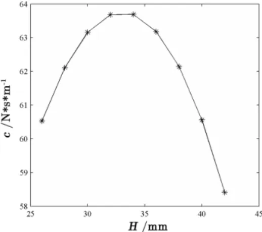
The damping performance of ECD with different thickness of magnet of 26.0, 28.0, 30.0, 32.0, 34.0, 36.0, 38.0, 40.0, 42.0 mm is shown in Figure 5. It is clearly seen the damping coefficient is not changed monotonically with respect to the thickness. It increases when the thickness of magnet varies from 26.0 mm to 34.0 mm and then decrease when its thickness is up to 42.0 mm. Thus, at given conditions, the thickness of magnet is chosen as 34.0 mm.
large thickness of the plate. Based on the changing trend represented by the curve and considera-tion of weight reducconsidera-tion, the thickness of the plate is chosen as 5 mm.
Figure 4: The damping coefficient of ECD at different velocities.
Figure 5: The damping coefficient of ECD with different thickness of magnet.
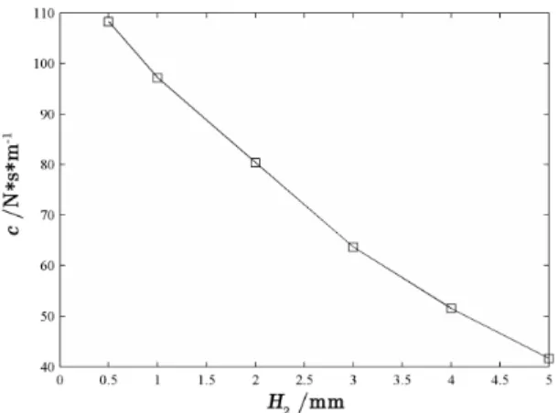
When the positions of the magnet are fixed, the damping performance of ECD is affected by the gap between the magnet and each copper plate since the distribution of magnetic field is change with vertical distance away from the surface of the magnet. The damping force and coefficient of ECD with different gap of 0.5, 1.0, 2.0, 3.0, 4.0, 5.0 mm are calculated at velocity of 0.1 m/s and the results are shown in Figure 7. It is shown the damping coefficient almost decreases with increas-ing gap. Because the stroke of the damper is usually limited within 1 mm, the gap at initial state is chosen as 2 mm to achieve high damping and prevent the plate from touching the magnet.
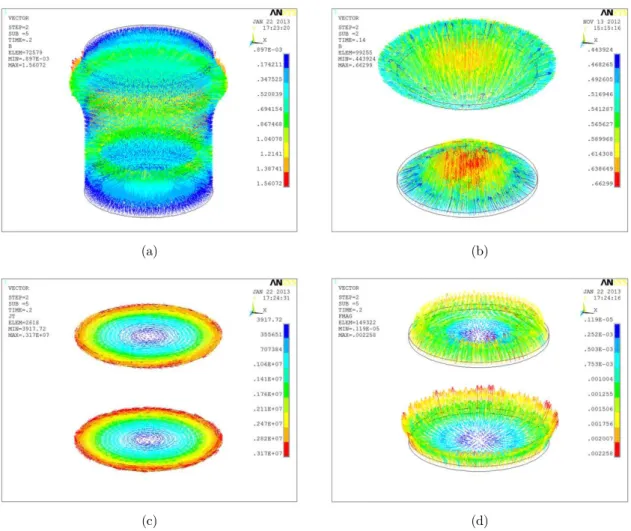
The chosen parameters are listed in Table 3. The FEM analysis results of designed ECD with selected parameters at initial state with velocity of 0.1 m/s are shown in Figure 8. Figure 8 (a) and (b) present the overall magnetic field distribution inside the ECD and nearby the two eddy current plates in the last iterative step of FEM simulation respectively. It can be found that the magnetic field distribution near to the upper and lower plates is not uniform, probably due to the unsymmet-ric installation of components of ECD prototype and disturbance of iron shield. Because the netic field intensity of lower plate is stronger and more uniform than that of upper plate, the mag-netic flux of lower plate varies more obviously and in turn induces larger and denser eddy current, as shown in Figure 8 (c). Since damping force, i.e. Lorentz force, is proportional to the magnetic flux, of course the resultant force generated from the lower plate is larger than that of upper plate. This result may refer to the plot of Figure 8 (d).
Figure 7: The damping coefficient of ECD with different gap between plate and magnet.
Parameter Value (mm)
Thickness of magnet 34
Thickness of copper plate 5
Gap between plate and magnet 2
Table 3: Selected parameters of ECD prototype.
these two parameters. The comparison results are listed in Table 4. It is shown that the damping force, as well as damping coefficient, generated from two-plate ECD is around double of that of one-plate damper. Thus it is indicated that the additional one-plate may highly enhance the damping per-formance of the ECD.
(a) (b)
(c) (d)
Figure 8: Transient analysis results of two copper plates ECD: (a) Overall magnetic field inside the ECD; (b) Magnetic field distribution; (c) Eddy current; (d) Lorentz force.
Damper Damping performance Upper plate Lower plate Whole damper
Proposed ECD (Two-plate)
Damping force (N) 3.99 4.64 8.63
Damping coefficient (Ns/m) / / 86.3
Conventional ECD (One-plate)
Damping force (N) 4.12 / 4.12
Damping coefficient (Ns/m) / / 41.2
4 EXPERIMENTAL WORK
4.1 Experimental Setup
The experimental setup of ECD includes electromagnetic exciter, signal generator, power amplifier, controller, force sensor, piezoelectric accelerometer, laser vibrometer, data acquisition unit and com-puters for controlling and data acquisition, as shown in Figure 9. The ECD and a spring are parallel to connected with the electromagnetic exciter. The excited signal is controlled by signal generator and controlling computer and amplified by power amplifier, then transferred to electromagnetic exciter. The acceleration and force signals are respectively measured by high precision accelerometer and force sensor and presented in data acquisition computer via data acquisition unit. Finally, the required damping performance of the tested ECD is derived from signal processing.
Figure 9: Experimental setup of the designed ECD.
The stroke and frequency of the mechanical device required to reduce vibration in aerospace applications usually range from 0 to 1 mm and 1 to 50 Hz respectively. Thus a series of tests on damping of ECD prototype subjected to sinusoid excitation with small and large amplitudes (around 0.1 and 1 mm) are carried out under frequencies of 1 Hz and then ranging from 2.5 to 50 Hz with spacing of 2.5 Hz. All damper specimens are inspected at beginning of tests and tested with a number of cycles. An example of the damping work measured in one complete cycle at the two different amplitudes is respectively shown in Figure 10 and Figure 11. The equivalent damping coef-ficient (Kelly, 2000) of the damper can be derived from the hysteresis loop area of the damping work and it is given by
2 2
(2
)
where W represents the area of hysteresis loop, and variables A and f are amplitude and
fre-quency of sinusoid excitation respectively. The damping coefficients of the ECD subjected to excita-tion of different frequencies are calculated by Eq. (1) and summarized in Table 5 and 6.
(a) (b) (c)
(d) (e) (f)
Figure 10: Damping work at amplitude of 0.1 mm: (a) 1 Hz; (b) 10 Hz; (c) 20 Hz; (d) 30 Hz; (e) 40 Hz; (f) 50 Hz.
4.2 Analysis of Experimental Results
The experimental data indicate that the damping performance of ECD relies on the amplitude and frequency of excitation signals. These behaviors are describes and explained below, to authors’ knowledge, for comprehension of the mechanism and design of the ECD.
When the excitation amplitude is small (around 0.1 mm), the damping coefficient of ECD slow-ly decreases with excitation frequency rising from 1 to 50 Hz and tends to numerical simulation result of 86.3 Ns/m. Because the damping force at small amplitude excitation is not large enough to ignore the effect of friction resistance, which is unable to be taken into account in 3D transient analysis module, the damping coefficients measured in experiments behaves larger than the simula-tion result. However, due to the fact that the Lorentz force augments with increasing frequencies and in turn the proportion of friction resistance is considerably abated, the measured value turns close to the simulation at high frequencies.
up to 50 Hz. It is caused by the skin effect (Hart, 2006), which happens in surfaces of copper plates and is induced by high velocity of the moving plates during the high frequency excitation process, associated with slowly rising of eddy current. The nature of this phenomenon is that the generated eddy currents may induce a magnetic field with opposite polarity as the applied field, thus reducing the effective magnetic field intensity and becoming significant at high velocity. At low frequencies, the experimental data are closed to numerical results because the skin effect is not significant in such conditions. With increasing frequencies, the moving shaft speeds up and the influence of skin effect become obvious, associated with rapid reduction of damping coefficient of the ECD. However, the acceleration rate of the shaft decreases when the frequency is larger than 30 Hz, leading to slow reduction of damping coefficient of ECD.
(a) (b) (c)
(d) (e) (f)
Figure 11: Damping work at amplitude of 1 mm: (a) 1 Hz; (b) 10 Hz; (c) 20 Hz; (d) 30 Hz; (e) 40 Hz; (f) 50 Hz.
Frequency (Hz) 1.0 2.5 5.0 7.5 10.0 12.5 15.0 17.5 20.0 22.5 25
Damping coefficient (Ns/m) 121.0 119.2 118.1 114.2 117.2 112.4 116.1 111.9 109.2 106.0 108.0
Frequency (Hz) 27.5 30 32.5 35 37.5 40 42.5 45 47.5 50
Damping coefficient (Ns/m) 106.8 113.3 111.3 110.9 98.4 100.8 95.1 85.5 89.7 89.6
Table 5: Damping coefficient of the ECD at amplitude of around 0.1 mm.
Frequency (Hz) 1.0 2.5 5.0 7.5 10.0 12.5 15.0 17.5 20.0 22.5 25
Damping coefficient (Ns/m) 97.8 85.6 77.5 61. 6 47.6 43.6 34.9 29.0 26.4 25.5 25.9
Frequency (Hz) 27.5 30 32.5 35 37.5 40 42.5 45 47.5 50
Damping coefficient (Ns/m) 25.9 23.2 23.7 22.0 21.5 19.7 20.7 19.3 17.4 16.2
Table 6: Damping coefficient of the ECD at amplitude of around 1 mm.
4.3 Comparison Between One-Plate ECD and Two-Plate ECD
In order to indicate the high damping of proposed ECD, a one-plate ECD prototype with the same dimensions is manufactured and the damping coefficients of the two types of damper derived from tests are compared. The comparison results are plotted in Figure 12. Since the damping work of ECD is done by the damping force of plates moved in magnetic field, the value of damping coeffi-cient of two-plate ECD should be around double times of that of one-plate ECD in theory. When the excitation amplitude is around 1 mm, the comparison results agree with it. But the experi-mental data at small amplitude of around 0.1 mm are in conflict with it. The damping coefficient of two-plate ECD is much larger than the one-plate ECD at excitation amplitude of. It may benefit from the fact that its dependence on initial equilibrium position is not as much as the latter one.
5 CONCLUSIONS
Based on eddy current theory and Sodano’s model, a new design of eddy current damper is pro-posed. Both numerical analysis and experimental work are conducted to investigate its damping performance. And some conclusions are drawn as follows:
(1) It is effective to utilize FEM to analyze the damping performance of ECDs. The damping resulting from 3D transient electromagnetic analysis at small amplitude, high frequency is obviously accurate compared with simulations in the other conditions.
(2) The proposed ECD has high damping performance at small amplitude excitation. The ex-perimental results show the damping coefficient of proposed ECD is dependent on velocity of damp-er, excited amplitude and frequency. At amplitude of 0.1 mm, its damping coefficient is up to 100 Ns/m when the excitation frequency is lower than 20 Hz. At excitation amplitude of 1 mm, the damping coefficient sharply reduces due to significant skin effect induced by high velocity of eddy plates.
(3) The damping performance of designed ECD is validated by experimental data. And it is in-dicated that the damping performance of two-plate ECD is superior to the one-plate ECD.
Acknowledgements
This work was finically supported by the National Science Foundation of China (Grant No. 51275022) and the Aero-nautical Science Foundation of China (Grant No 2015ZD51049).
References
Albertz D., Dappen S. and Henneberger G., (1996). Calculation of the 3D nonlinear eddy current field in moving conductors and its application to braking systems, IEEE Transactions on Magnetics 32(3): 768 – 771.
Bae J.S., Hwang J.H., Park J.S., et al., (2009). Modeling and experiments on eddy current damping caused by a permanent magnet in a conductive tube, Journal of Mechanical Science and Technology 23(11): 3024-3035.
Bae J.S., Kwak M.K., Inman D.J., (2005). Vibration suppression of a cantilever beam using eddy current damper, Journal of Sound and Vibration 284(3-5): 805-824.
Baranski M., Demenko A., Lyskawinski W., et al., (2011). Finite element analysis of transient electromagnetic-thermal phenomena in a squirrel cage motor, International Journal for Computation and Mathematics in Electrical and Electronic Engineering 30(3): 832 – 840.
Bíró O., Koczka G., Preis K., (2014). Finite element solution of nonlinear eddy current problems with periodic exci-tation and its industrial applications, Applied Numerical Mathematics 79: 3-17.
Cheah S.K. and Sodano H.A., (2008). Novel eddy current damping mechanism for passive magnetic bearings, Jour-nal of Vibration and Control 14(11): 1749-1766.
Cunningham R.E., (1986). Passive eddy current damping as a means of vibration control in cryogenic turbomachin-ery, NASA Technical Paper number NASA-TP-2562, Access No. N86–24722.
Ebrahimi B., Khamesee M.B., Golnaraghi M.F., (2008). Design and modeling of a magnetic shock absorber based on eddy current damping effect, Journal of Sound and Vibration 315(4): 875-889.
Gunter E.J., Humphris R.R., Severson S.J., (1983). Design study of magnetic eddy current vibration dampers for application to cryogenic turbomachinery, University of Virginia Report UVA/528210/MAE84/101, NASA Grant NAG-3–263.
Hart H.W., (2006). Engineering Electromagnetics, Seventh Edition, New York: McGraw Hill.
Huo L.S., Song G.B., Nagarajaiah S., et al., (2012). Semi-active vibration suppression of a space truss structure using a fault tolerant controller, Journal of Vibration and Control 18(10): 1436-1453.
Kelly S.G., (2000). Fundamentals of mechanical vibrations, second edition, McGraw-Hill.
Kienholtz D.A., Smith C.A., and Haile W.B., (1996). A magnetically damped vibration isolation system for a space shuttle payload, Proceeding of the SPIE International Symposium on Smart Structures and Materials, San Diego, CA, 2720: 272–280.
Kwag D.G., Bae J.S., and Hwang J.H., (2007). Experimental study for dynamic characteristics of an eddy current shock absorber, Journal of the Korean Society Aeronautical and Space Sciences 35(12): 1089-1094.
Laborenz J., Krack M., Panning L., et al., (2011). Eddy current damper for turbine blading: electromagnetic finite element analysis and measurement results, Journal of Engineering for Gas Turbines and Power 134(4): 042504. Schmid M., Varga P., (1992). Analysis of vibration-isolating systems for scanning tunnelling microscopes, Ultrami-croscopy 42–44: 1610–1615.
Sodano H.A., Bae J.S., (2004). Eddy current damping in structures, Shock and Vibration Digest 36(6): 469-478. Sodano H.A., Bae J.S., Inman D.J., et al., (2005). Concept and model of eddy current damper for vibration suppres-sion of a beam, Journal of Sound and Vibration 288(4): 1177-1196.
Sodano H.A., Bae J.S., Inman D.J., et al., (2006). Improved concept and model of eddy current damper, Journal of Vibration and Acoustics 128(3): 294-302.
Wijker J.J., (2004). Mechanical vibrations in spacecraft design, Berlin and Heidelberg: Springer.