Abstract
A spatial state-space formulation based on the linear two-dimensional piezoelasticity theory and involving local/global trans-fer matrices is applied to investigate the active vibration suppres-sion of a simply supported, arbitrarily thick, orthotropic elastic beam, imperfectly integrated with spatially distributed piezoelec-tric actuator and sensor layers on its top and bottom surfaces, respectively. A linear spring-layer model is adopted to simulate the bonding imperfections between the host structure and the piezoelectric layers. To assist control system design, system identi-fication is conducted by applying a frequency domain subspace approximation method with N4SID algorithm based on the first five structural modes of the system. The state space model is constructed from system identification and used for state estima-tion and development of control algorithm. A linear quadratic Gaussian (LQG) optimal controller is subsequently designed and simulated based on the identified model in order to actively con-trol the response of the smart structure in both frequency and time domains.
Keywords
vibration suppression, interfacial imperfection, exact solution, system identification, optimal control, Kalman observer.
Active Vibration Control of an Arbitrary Thick
Piezolaminated Beam with Imperfectly Integrated
Sensor and Actuator Layers
1 INTRODUCTION
Measuring and control of distributed parameter systems (DPSs) using conventional spatially dis-crete sensors and actuators (e.g., accelerometers, strain gages, and pressure transducers, etc.) intro-duces various practical problems, especially if these devices are installed at (or near) modal nodes or lines of DPSs (Inman 1989). Some natural frequencies and mode shapes may be overlooked, and observability/controllability problems could occur. Consequently, development of spatially
distrib-Seyyed M. Hasheminejada
M. Vahedi b
A. Hoshangi c
a Acoustics Research Laboratory,
School of Mechanical Engineering Iran University of Science and Technology, Narmak, Tehran 16846-13114 Iran
b Department of Mechanical
Engineer-ing, Saveh Branch, Islamic Azad Uni-versity, Saveh, Iran
vahedi.majid@gmail.com
c Department of Mechanical
Engineer-ing, Saveh Branch, Islamic Azad Uni-versity, Saveh, Iran
Latin American Journal of Solids and Structures 11 (2014) 1957-1982
uted sensors and actuators are highly crucial for structural identification and control of new-generation high performance structures. Piezoelectric layers are excellent choices for distributed sensor and actuator applications, due to their great sensitivity and simple application to elastic continua. The distributed piezoelectric sensing element laminated on an elastic continuum reacts to mechanical strains and generates output voltage to actively monitor the structural oscillations on account of the direct piezoelectric effects. On the other hand, the distributed actuator element pro-duces control forces/moments and restrains the undesirable structural vibrations through the con-verse piezoelectric phenomenon (Cady, (1946), Baileyand Hubbard (1985), Crawley (1987)). Recent literature reviews show that significant achievements have been obtained on distributed structural modelling, identification, and active vibration or shape control of smart beam, plate and shell struc-tures integrated with spatially continuous piezoelectric sensor and actuator layers (Chee et al. (2000), Sunar and Rao (1999), Saravanos and Heyliger (1995), Kapuria and Yasin(2010), Bendary et al. (2010), Kerur and Ghosh(2011)). In the following paragraph, a brief overview regarding key contributions on active vibration control of smart composite beams, integrated (surface-bonded or embedded) with distributed piezoelectric sensor/actuator layers, is presented.
constant-Latin American Journal of Solids and Structures 11 (2014) 1957-1982
feed-Latin American Journal of Solids and Structures 11 (2014) 1957-1982
Latin American Journal of Solids and Structures 11 (2014) 1957-1982
optimal close loop control algorithm to investigate modeling and vibration control of a laminated composite cantilever beam with integrated piezoelectric damping-modal actuators/sensors. A com-pensator based on the first three modes was employed to perform the shape control of the smart beam and attenuate the vibration spillover. Stavroulakis et al. (2005) developed a finite element model based on classical engineering beam bending theory and designed LQR and H2 optimal (ro-bust) control strategies for active vibration control of a slender beam integrated with piezoelectric sensors and actuators on its upper and lower surfaces. The comparison between the two proposed control laws demonstrated that, while both strategies are successful, the second approach is favored due to its robustness characteristics. Edery-Azulay and Abramovich (2006) investigated the effects of continuous actuator and sensor piezo-layers performing in closed-loop, on the active damping of vibrating piezo-composite beams, using a first order shear deformation theory (FSDT). The accu-mulated voltage on the sensor layer was transferred to the piezoelectric actuator layer in order to actively attenuate the structural vibrations. The effect of extension and shear piezoelectric mecha-nisms, and also the feedback gain value on the active suppression of vibrating piezo-composite beam was investigated. Vasques and Rodrigues (2006) presented a finite element study on the active vi-bration control of smart three layer beams composed of isotropic materials with piezoelectric sensor and actuator layers, and made comparisons between classical and optimal linear quadratic Gaussian (LQG) feedback control strategies. Manjunath and Bandyopadhyay (2006) used Timoshenko beam theory, and finite element and state space methods to design a periodic output feedback (POF) controller for suppressing the first three modes of vibration of a flexible cantilever beam structure with embedded shear piezoelectric sensor and actuator layers. The effect of sensor location (while keeping the actuator location fixed) on the performance of the controller was evaluated and dis-cussed. Zabihollah et al. (2007) used an experimental set-up along with a finite element model based on the coupled layerwise theories (LWTs) with layerwise linear variation of in-plane dis-placements to investigate optimal (LQR) vibration control of laminated piezoelectric composite beams. The LWTs was found to yield accurate results, while the computational cost amplifies with increasing the number of layers. Rao and Narayanan (2007) used the finite element model based on the transfer matrix approach to study the active flexural wave propagation control in multi-span uniform beams resting on periodically spaced, rigid simple supports with built-in distributed piezoe-lectric actuators and sensors, subjected to a moving harmonic pressure field. It was shown that by appropriate selection of the control gains, the response amplitudes at coincidence frequency can be actively controlled and also the widths and locations of the stop bands can be considerably in-creased. Zhang et al. (2008) presented results on LQG and robust H∞ control strategies for active
vibration suppression of a flexible cantilever beam with surface-bonded piezoelectric sensors and actuators. The effectiveness and feasibility of the control methods were demonstrated through some simulation results. It was shown that robust H∞ control strategy has strong robustness with respect
Latin American Journal of Solids and Structures 11 (2014) 1957-1982
vibration control of a flexible composite beam with built-in piezoelectric elements in the form of surface-bonded piezoelectric layers used as sensor and actuator, aiming for robustness with respect to parametric uncertainties and external loads. The discretization was carried out using finite ele-ments, and the simulations were performed in the MATLAB environment demonstrating that the robust H2 and H∞-controllers can achieve effective suppression of low-frequency disturbed
vibra-tions of the composite beam while they preserve the efficiency in case of signal excessiveness due to high-frequency modes. Bendary et al. (2010) used the classical laminate (Euler-Bernoulli) beam theory to present a finite element model for the static and dynamic analysis of an intelligent ad-vanced beam structure integrated with a distributed piezoelectric actuator layer and subjected to axial/transverse mechanical loads in addition to electrical load. The beam was composed of an iso-tropic and/or anisoiso-tropic substrate, completely or partially covered with the piezoelectric actuator layer. Kapuria and Yasin (2010), presented an efficient finite element model based on a layerwise theory with a quadratic variation of electric potential across the piezoelectric layers for active vibra-tion control response of smart laminated cantilever beams integrated with electroded piezoelectric sensors and actuators. A reduced-order state space model is constructed and two control strategies, namely a constant gain velocity feedback (CGVF), and optimal LQR/LQG control strategy were considered for single-input–single-output (SISO) and multi-input–multi-output (MIMO) control configurations under step and impulse excitations. It was shown that multi-segment electrodes dis-play faster attenuation in the closed-loop response than single-segment ones for all control laws. Also, the peak control voltages required for the same settling time are smaller in LQG control than the LQR control for both single and multi-segment electrodes. Zhang et al. (2010) proposed an ef-fective procedure, based on the Linear Quadratic Gauss (LQG) optimal control approach, applica-tion of ANSYS software, and modal analysis, to suppress the vibraapplica-tions of flexible intelligent canti-lever beams with the piezoelectric sensors/actuators asymmetrically collocated on both sides of the same position of the host structure. Chandiramani (2004) investigated optimal LQR control of a thin-walled pre-twisted, doubly tapered, rotating beam comprised of an orthotropic host with sur-face-bonded transversely isotropic piezoelectric sensor-actuator pairs using a higher-order shear de-formation theory (HSDT). Parametric studies on effects of ply-angle, rotation speed, pretwist, ta-per, rotor mass, and actuator saturation voltage limit, were performed. It was demonstrated that the HSDT, as compared to un-shearable and first-order shear models, provides conservative data on the lowest coupled natural frequencies, which is useful for passive and active control designs.
experi-Latin American Journal of Solids and Structures 11 (2014) 1957-1982
mental tools for the design and analysis of thick piezo-laminated beams or panels with optimal vi-brational control characteristics. Such components are of practical interest in development of smart microelectromechanical systems (MEMS) (Wang (1998), Zhang et al. (2006)), where a very accurate displacement control is required.
2 FORMULATION
An orthotropic beam (length L, total thickness H), bonded with piezoelectric actuator and sensor layers on its top and bottom surfaces and in state of plane stress, is considered (see Figure 1). The
(Oxyz) coordinate system is set at the corner of the smart structure on the bottom surface of the
sensor layer, as shown in Figure 1. Here, the nonzero stress components are σ
!!, σ!!, and σ!" only, which are independent of y. Also, there are additionally two nonzero y-independent electric dis-placement components D! and D! in the piezoelectric layers. In the following two subsections, the
basic governing equations for the orthotropic host beam and the piezoelectric layers will be derived in (spatial) state-space form.
Figure 1: Problem configuration.
2.1 The spatial state space model
Latin American Journal of Solids and Structures 11 (2014) 1957-1982
Σ!!
Σ!! Σ!"
=
C!! C!" 0
C!" C!! 0
0 0 C!!
ϵ
!! ϵ
!!
2ϵ
!" −
0 Q!"
0 Q!!
Q!" 0
E!
E!
,
D!
D! =
0 0 Q!"
Q!" Q!! 0
ϵ
!! ϵ
!!
2ϵ
!"
+ G!! 0
0 G!!
E!
E! ,
(1)
where the pertinent piezoelectric constants, C!", Q!" , G!", and the strain, ϵ
!", and the electric field components, E!, are respectively defined as
C!!=c
!!−c!"! /c!! , C!"=c!!−c!" c!" /c!!,
C!!=c!!−c!"! /c
!!, C!!=c!! ,
Q!"=e!"−c!" e!" /c!!, Q!"=e!", G
!!=ε!!, G!!=ε!!−e!"! /c!!,
(2a)
ϵ
!!=
!!
!! , ϵ!!=
!!
!! , ϵ!"=1 2( !!
!!+
!!
!!),
E!=−
!!
!! E!=−
!!
!!
(2b)
where φ is the electric potential, and U and W denote the axial and transverse displacement compo-nents, respectively (see Figure 1). Also, in the absence of body forces and free charge density, the equations of motion and the Gaussian equation of electric equilibrium are written as (Cheng et al. (2000))
∇.Σ=ρ Ψ,
∇.D!=0, (3)
where Ψ= U,W is the displacement vector, ρ is the mass density, and Σ= Σ
!! Σ!! Σ!" ! and
D! = D! D! ! are the stress and electric displacement vectors, respectively.
Following the spatial state-space approach developed by Bahar (1975), by direct substitution of the kinematic relations (2b) into the constitutive relations (1), and subsequent incorporation of the results into the equations of motion/equilibrium (3), after some tedious manipulations, one advan-tageously arrives at
!!
!!=K!
V, (4)
Latin American Journal of Solids and Structures 11 (2014) 1957-1982
K!=
0 0 0
0 0 0
0 0 0
ρ ∂!
∂t! −
∂
∂x 0
− ∂
∂x
1
C!! −
Q!"
C!! ∂
∂x
0 −Q!"
C!!
∂
∂x −
α!
C!!
∂!
∂x!
G!! γ − α ! γ ∂ ∂x Q!! γ − α ! γ ∂
∂x α!
∂!
∂x!+ρ
∂!
∂t! α ! γ ∂ ∂x Q!! γ α ! γ ∂
∂x −
G!!
γ
0 0 0
0 0 0
0 0 0
,
in which
γ=C!!G!!+Q!!! , α!=C!!Q!"−C!"Q!!, α!=C!"G!!+Q!"Q!!,
α!=C!!G!!+Q!"! , α
! =
!
!(C!" α
!−Q!" α!)−C!!, .
Also, assuming simply supported end conditions, i.e.,
W=!!! =!=0. (!=0,!) (5)
the state vector, !, may be expanded in the form(Bian et al. (2006))
!!! ! !! ! !!" ! = !!!! !
!! !"#(!"#/!)
! ! !"#(!"#/!)
!!!! !!!! !!!"#(!"#/!)
! !!"#(!"#/!)
!!!! !
!"!"#(!"#/!)
! !!!! / !!!! ! !"#(!"#/!)
!!"#, (6)
where != −1, and ! is the radial frequency, and one should note that the piezoelectric constants
!!!! and !!!! for the sensor material (see Eqs. 2a) are used as the normalization constants in the above equation and throughout the formulation. Substituting the above expansions into the state equation (4), yields
!!
!" =!!!, (7)
where !=!/!, and the vector !(!)= !
!! ! !! ! !!" !
!
contains the relevant modal coefficients. Also, the coefficient matrix !! may be associated with either the sensor or the actuator
piezoelectric layer, respectively denoted by !! or !!, whose elements are given in the Appendix.
Latin American Journal of Solids and Structures 11 (2014) 1957-1982
! ! =!"# !"! ! ! =0 , (0 ≤ ! ≤ !!)
! ! =!"# !−!! !! ! !=!! . (!! ≤ ! ≤ 1) (8)
where !!= ℎ!/! and !!= (ℎ! + ℎ!)/! (see Figure 1). Thus, using the above relations, the
state variables at the lower surface of the sensor/actuator layer may simply be related to those at the upper surface in the form:
! ! =!! =!!! ! =0 ,
! !=1 = !!! !=!! ,
(9a)
(9b)
where !! =!"# !!!! and !!=!"# 1−!! !! .
For the host orthotropic layer, one can readily follow the above procedure to drive the pertinent matrix equations. In the state of plane-stress, the constitutive relations for the orthotropic layer is provided in the Appendix. In particular, with the simply supported end condition assumption, the state vector, !, may be expanded in the form
! !!
!
!
!!"
= !!!! !
!! !"# !"# !
! ! !"# !"# !
! !!"# !"# !
!!!! !
!"!"# !"# !
!!"#, (10)
and ! and ! denote the axial and transverse displacement components of the host layer,
respec-tively (see Figure 1). Also, the modal state space Eq. (7) may be re-written for the orthotropic layer in the form !!"!=!!!, in which !(!)= !!! ! ! !!" ! is the corresponding modal state
vec-tor, and !! is a 4×4 modal coefficient matrix given in the Appendix. The solution to the latter
state equation can be written as:
! ! =!"#(!−!!)!! ! !! (!! ≤ ! ≤ !!) (11)
Thus, using the above relations, the state variables at the lower surface of the host layer may simp-ly be related to those at the upper surface as:
! ! =!! =!!! ! =!! , (12)
where !!=!"# !!!! .
2.2 The interface/boundary conditions and the displacement response
Latin American Journal of Solids and Structures 11 (2014) 1957-1982
mechanical conditions at the two interfaces between the host structure and the piezoelectric actua-tor and sensor layers are respectively written as
σ
!!= Σ!!
!
= w−W! /K!!,
σ
!"= Σ!" !
= u−U! /K
! !
, (ζ=ζ!) (13a)
σ
!!= Σ!!
!
= W!−w /K
!
!
,
σ
!"= Σ!" !
= U!−u /K
!
!
. (ζ=ζ!) (13b)
where the indices “s” and “a” refer to the sensor and actuator layers, respectively. Also, by virtue of Eqs. (6) and (10), the interface conditions (13) can be written in the following matrix form
W ζ=ζ! =P!V
! ζ=ζ! , (14a)
V
! ζ=ζ! =P!W ζ=ζ! , (14b)
where V
!= Σ!! U W Σ!"
!
is the mechanical part of V, and P! and P! are the interfacial
trans-fer matrices associated with the sensor and actuator layers, respectively, defined as
P! =
1 0
0 1
0 0
0 !!
! !!!
!
!
!!!!!! !
! 0
0 0
1 0
0 1
, P! =
1 0
0 1
0 0
0 !!
! !!!
!
!
!!!!!!
!
! 0
0 0
1 0
0 1
.
Next, we suppose that the laminated beam is subjected to a distributed dynamic normal mechanical harmonic load, q(x,t)=Q x exp iωt , acting over the area (L
!≤x≤L!+a!) on its top surface (actuator layer), while it is traction-free at the bottom surface (sensor layer) (see Figure 1). Thus, the load amplitude, Q x , may be expanded as
Q x =C!!! qsin m
πx
L ,
!
!!!
(15)
where q=!!!
!!
! Q x sin mπx L
!!!!! !!
dx. Also, the electric boundary condition for the piezoelectric
actuator segment, distributed over the area L!≤x≤L!+a! (see Figure 1), may be written as
(Ray et al. (1992))
φ!(x,z=H,t)=Φ! x exp iωt , (16a) φ!(x,z=h!+h!,t)=0, (16b)
Latin American Journal of Solids and Structures 11 (2014) 1957-1982
!! ! =! !!!
!
/ !!!! !
!!"#
!"#
!
!
!!!
, (17)
where !! =
!
!" !!!! / !!!! !!
! !"# !"# ! !!!!!
!!
!". Subsequent use of Eqs. (9b) and (16a), after
some tedious manipulations, one obtains
!! !=1
=!!!! !=!! +!! , (18)
where the coefficient matrix !! is given in the Appendix, !! =
(!! !! !"
) !!
!"
!! !"
!!
!" !!
!" !, and !
!
!"
(!,!=1,2,…,6) denote the ij-th elements of the transfer matrix !!. Furthermore, the electric boundary conditions for piezoelectric sensor are (Ray
et al. (1992))
!!!(!,!=0,!)=0,
!!(!,! =ℎ!,!)=0.
(19)
Moreover, by virtue of Eqs. (9a) and (19), after some manipulations, one obtains
!! ! =!!
=!!!! ! =0 , (20)
where the coefficient matrix !! is given in the Appendix. Finally, the state Eqs. (9), (12), (14), (18) and (20), may advantageously be combined to obtain the global transfer relation in the form
!! ! =1 =! !! !=0 +!! , (21)
where !=!!!!!!!!!! is the 4×4 global transfer matrix pertaining to the laminated smart
struc-ture.
Now, by making use of the boundary conditions (15), (16), and (19) in the state Eq. (21), after some manipulations, one arrives at the following matrix relation for the displacement components at the lower surface of the sensor layer:
!! !=0
!! !=0 =
!!!! !−(!!!!
!" !!
!" )
−(!!!!
!" !!
!"
) , (22)
where !! = !!" !!"
!!" !!" , and !!" (!,!=1,2,…,4) refer to the elements of global transfer matrix !.
Thus, the displacement response of the system can readily be obtained from Eqs. (9) and (12). Direct implementation of Eqs. (22) into the state solution (9a), keeping in mind the mechanical and electrical boundary conditions for the sensor layer (i.e., !!!! =!!"
!
=0 at ! =0 and !!! =0 at ! =
0, along with !!=0 at !=!!), after some manipulations, one obtains the expression for the modal
Latin American Journal of Solids and Structures 11 (2014) 1957-1982 !! !=0 =−!!!"!! !=0 +!!!"!! !=0 /!!!!. (23)
Thus, the average induced voltage in the sensor segment, which is distributed over the area !! ≤! ≤!!+!! (see Figure 1), can be obtained by substituting Eq. (23) into Eq. (17) and inte-grating electric potential on sensor length in the form
!!"
!
! =0 =!
!!!! / !!!!
!! !! !=0 !"#
!"#
! !" !!!!!
!!
!
!!!
. (24)
where b is beam width and !!=(!!!!/ℎ!) !! is the sensor capacitance.
2.3 System identification
In the last decades, subspace state-space identification methods, which can estimate the system order and matrices from input-output data without prior knowledge of the plant under study, have progressed significantly for identifying state-space models. The N4SID algorithm (Overschee and Moor (1994)) is one particular type of subspace algorithm whose numerical implementation is of-fered in Matlab’s System Identification Toolbox (Ljung (2001)). It relies on subspace fitting strate-gies for the approximation of the extended observability matrix. In this paper, the above mentioned frequency domain subspace-based approximation scheme is applied to estimate system order and matrices of the entire fluid-structure coupled problem. The process begins with collection of open-loop input-output (actuator/sensor voltage) data from experimental or numerical simulations. In particular, one can measure or calculate the sensor segment output voltage V!(see Eq. 23), in
re-sponse to an actuator segment input voltage signal, φ!, and use the data to identify the system
state-space model. Accordingly, using the above procedure, the linear n-th order single input– single output (SISO) continuous time state space model of the piezo-laminated beam can be constructed in the form
x t =A x t + B! | B!
w t
u t ,
y t =C x t + D! | D!
w t
u t ,
(25)
where u(t) i s the input vector (control signal), y(t) is the output vector (measured signal),
x(t)∈R! is the state vector, w(t) ∈R is the exogenous input vector (e.g., reference signal, disturb-ances, noise, etc), and the system matrices A∈R!×!, B!∈R!, B!∈R!×!, C∈R!×!, D!∈R and D!∈R are estimated from the input vector u(t) and the output vector y(t), by utilizing Matlab’s System Identification Toolbox, as explained above.
2.4 Controller design
Latin American Journal of Solids and Structures 11 (2014) 1957-1982
Consequently, before designing the optimal controller, we shall consider the state-space representa-tion based on the modal coordinates, where the number of equarepresenta-tions is significantly lower, while the accuracy of the analysis has not suffered. Accordingly, following the standard procedure outlined by Gawronski (2004), the modal form of linear time-invariant (LTI) equations of motion (25), with the continuous system realization advantageously be written as
z t =A! z t +B! u t +Ξ w!,
y t =C! z t +w !,
(26)
where Ξ is disturbance matrix, w
! is the measurement noise, w! is associated with the disturbance
signals (i.e., it may include actuator noise and/or any external random disturbance), and obtaining the modal state-space representation triple A!,B! ,C! requires some relatively tedious
manipula-tions, which is explained by Maciejowski (1989). Also, the measurement noise, w
!, and the process noise, w!, are generally assumed to be uncorrelated zero-mean Gaussian stochastic processes with constant power spectral density matrices, !! and !!, respectively. In other words, w
! and w! are white noise processes with covariances
E w
! t w! τ ! =!! δ(t−τ),
E Ξw! t w! τ !Ξ! =!! δ(t−τ),
E w! t w
! τ ! = E w! t w! τ ! =0,
(27)
where E is the expectation operator and δ(t−τ) is the delta function.
The LQR problem, where all the states are known, is the deterministic initial value problem: Given the system z t =A! z t +B! u t with a given non-zero initial state z(0), find the input
signal u(t) which puts the system back to the zero state (z=0) in an optimal manner, i.e. by
min-imizing the deterministic cost
J= ! z(t)!Q z(t)+ u t !R u(t) dt
! , (28)
where Q and R are suitably chosen constant weighting matrices, such that Q=Q! ≥0, and R=R!≥0. The first step in the solution of the LQG problem consists of finding the optimal
con-trol to a deterministic linear quadratic regulator (LQR) problem: namely, the above LQG problem without w! and w
!. The optimal solution to this problem can be written in terms of the simple
state feedback law
u t =−K!z t , (29)
where z is the estimated state, and K!= R!!B!!X , in which X (X=X!≥0) is the unique
positive-semi definite solution of the algebraic Riccati equation
A!!X+X A!−X B! R!!B!!X+Q=0. (30)
sys-Latin American Journal of Solids and Structures 11 (2014) 1957-1982
tem in presence of noisy measurements, and is independent of Q and R. The Kalman filter has the structure of an ordinary state estimator or observer with:
z t =A
! z t +B! u t +K! y t −C!z t , (31)
where K! = YC!!!!!! is the optimal choice for observer gain which minimizes the mean square
error E z−z ! z−z , and Y=Y!≥ 0 is the unique positive-semi definite solution of the estima-tor algebraic Riccati equation
Y A!!+A! Y −Y C!!V!!C!Y+ !! =0. (32)
Lastly, using the modal state-space realization (26), the state feedback law (29), and the estimated state equations (31), after some straight forward manipulations, one can obtain the closed-loop sys-tem dynamic equations in the form
!
!" ! !
! ! =
!!−!! !! !! !!
0 !!− !!!!
! !
! ! +
! !!
! !!− !!!! , (33)
where ! ! =! ! −! ! . This shows that the closed-loop poles are simply the combination of the poles of the deterministic LQR system (eigenvalues of !!−!! !!) and the poles of the Kalman
filter (eigenvalues of !!− !!!!), which is exactly as predicted by the Separation Theorem (Skogestad and (2005)). This completes the necessary background required for the analysis of the problem. Next, we consider some numerical examples.
3 RESULTS
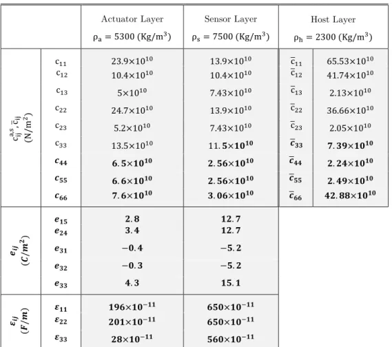
In this section we consider some numerical examples. Realizing the large number of parameters involved here while keeping in view our computing hardware limitations, we confine our attention to a particular problem (see Figure 1). The host layer (h!=0.003m,L=0.6m) is assumed to be made of an orthotropic material with the material properties as given in Table 1 (Bian et al. (2006)). The actuator/sensor pair segments are assumed to be perfectly bonded (K!!,K!!,K!!,K!!=0)
on the upper/lower surfaces of the core orthotropic layer, with the following geometric ters:(h!=h! =0.00025m, L! =L! =0.48m,a! =a!=0.07m), and fabricated from Ba!NaNb!O!"/
Latin American Journal of Solids and Structures 11 (2014) 1957-1982 Actuator Layer
ρ!=5300 (Kg/m
! )
Sensor Layer
ρ!=7500 (Kg/m !
)
Host Layer
ρ!=2300 (Kg/m! )
c!"
!
,
! , c!"
(
N
/
m
!)
c
!! 23.9×10
!" 13
.9×10!" c
!! 65.53×10
!"
c
!" 10.4×10!" 10
.4×10!" c
!" 41.74×10!"
c!" 5
×10!" 7.43×10!" c!" 2.13×10!" c
!! 24.7×10!" 13
.9×10!" c
!! 36.66×10!"
c!" 5
.2×10!" 7.43×10!" c!" 2.05×10!"
c!! 13
.5×10!" 11.!×!"!" !!! !.!"×!"!"
!
!! !.!×!"!"
!.!"×!"!" !
!! !.!"×!"!"
!!! !
.!×!"!" !.!"×!"!" !!! !.!"×!"!" !!! !.!×!"!" !.!"×!"!" !!! !".!!×!"!"
!!"
(
!
/
!
! )
!!" !.! !".!
!
!" !.! !".!
!!" −!.! −!.!
!!" −!.! −!.!
!!! !.! !".!
!!"
(
!
/
!
) !
!! !"#×!"!!! !"#×!"!!!
!
!! !"#×!"!!! !"#×!"!!!
!!! !"
×!"!!! !"#×!"!!!
Table 1: Mechanical and electrical properties of the constituent materials.
Also, two types of external loads are considered: a uniformly distributed transverse impulse load, and a uniformly distributed transverse random (Gaussian) load. A general Mathematica code was constructed for computing the global modal transfer matrix, !=!!!!!!!!!!, obtaining the sensor
modal displacement components (!!,!!) from Eqs. (22), and ultimately calculating the average induced voltage in the sensor segment by numerical integration of Eq. (24). Computations were performed on a network of personal computer with a maximum truncation constant of !!"# =10
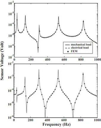
in Fourier expansions (6), (10), (15), (17) and (25) to assure convergence in the high frequency range. Before presenting the main results, the overall validity of the formulation should be demon-strated. To do this, we computed the sensor voltage amplitude, versus the excitation frequency for our three-layered !"
!!"!"!!!"-orthotropic-PZT4 beam subjected to either an external uniformly distributed constant amplitude transverse load (! !,! =1!!"# N; !
!=0.2!,!!=0.01!), or a
uniformly distributed constant amplitude electrical load (!! !,! =!,! =1!
!"#!
Latin American Journal of Solids and Structures 11 (2014) 1957-1982
orthotropic layer. In addition, mesh size sensitivity analysis was carried out for numerical conver-gence checking.
Figure 2: Frequency response plots for the piezolaminate beam subjected
to uniformly distributed electromechanical loads.
For the design and simulation of the control system, MATLAB® and Simulink softwares were utilized, and a Single-Input Single-Output (SISO) configuration, with the output being the voltage at the sensor segment location, and the input being the control voltage applied into the actuator segment of the top piezoelectric layer (see Figure 1), was considered. Next, we set the thicknesses of the top and bottom piezoelectric layers nearly equal to zero (ℎ!=ℎ! ≈0) and computed the
fre-quency response of a moderately thick simply supported 0∘ graphite-epoxy (AS4/3501-6) composite beam (ℎ!=0.0254!,!=0.381!) subjected to an external uniformly distributed constant
ampli-tude transverse load (! !,! =100!!"# N; !!=0.06!,!
!=0.02!), with the material properties as
given in Table 1 of Ref. Calım (2009). The first five calculated system resonance (peak) frequencies, as tabulated in the last column of Table 2a (the associated frequency response curve is not shown for briefness), demonstrate good agreements with those presented in Refs. (Calım (2009), Chan-drashekhara and Bangera (1992), Rao and Ganesan (1997)) which are based on the high order shear deformation theories. As a further check, we set the thickness of the orthotropic core layer and the
Latin American Journal of Solids and Structures 11 (2014) 1957-1982 (! !,! =100!!"# N; !!=0.06!,!
!=0.02!), with the material
parameters
as given in Table 1 of Ref.
(Yang and Zhifei (2009)). The first four calculated system non-dimensional resonance fre-quencies,!ℎ! !! !!!
!
, as tabulated in the last column of Table 2b, demonstrate good agreements with those presented in Refs. (Yang and Zhifei (2009)) which were obtained using a state-space based differential quadrature method (SSDQM) and exact piezoelasticity theory.
Mode
No. Calım (2009)
Chandrashekhara and Bangera (1992)
Rao and
Ganesan (1997) Present
1 0.753 0.756 0.754 0.754
2 2.544 2.554 2.555 2.548
3 4.711 4.742 4.753 4.733
4 6.956 7.032 7.052 7.016
5 9.191 9.355 9.383 9.312
Table 2a: Comparison of the calculated resonance frequencies (in kHz) of a moderately thick simply supported
graphite-epoxy beam with the available data based on high order shear deformation theories.
Mode No. Zhang et al.
(2006) Present
1 0.0211 0.0212
2 0.0828 0.0829
3 0.1805 0.1805
4 0.3082 0.3086
Table 2b: Comparison of the calculated dimensionless resonance frequencies of a moderately thick simply supported
!"#$!! piezoelectric beam with the available data based on the piezoelasticity theory.
Latin American Journal of Solids and Structures 11 (2014) 1957-1982
Figure 3: Comparison of the frequency response functions of real and identified models.
In the optimal control strategy, the relative magnitudes of ! and ! are chosen to compromise the
requirements on minimizing vibration energy against control voltage. The performance of the closed-loop system is classically defined through the closed-loop parameters such the bandwidth, the root-mean-square system response, or settling time and overshoot. These quantities are implicitly reflected in the weighting matrix, !, in an obscure manner. Consequently, approximate
relation-ships between weights and closed-loop performance may be derived for structures, giving guidelines as to how to determine the weights that shape the closed-loop system performance that meets the requirements. Figure 4 shows the frequency response magnitude (in dB) of closed-loop system for LQR weighting matrices (!=!",!=!";!=10!
,10! ,10!"
,!=0.1,1) and for a fixed actua-tor/sensor interface imperfection parameter (!=0). The most important observations are as fol-lows. Decreasing the control input weighting factor ! (i.e., relieving the bound restriction on the applied control force) leads to a notable decrease in the closed-loop frequency response amplitudes. Also increasing the weighting factor 10!<! <10!", has a prominent diminishing effect on the
frequency response amplitudes. This reduction is observed to be most severe for the largest voltage amplitudes observed among the first five modes, which may be directly linked to the selected diago-nal form of the state weighting matrix !=!". In other words, it is seen that the developed control
mechanism has a significant influence on controlling all five modes, especially for !=10!",!=0.1,
Latin American Journal of Solids and Structures 11 (2014) 1957-1982
Figure 4: Frequency response functions for selected weighting factors and !=0.
Finally, Figures 5a,b display the vibration control performance of the simply-supported piezo-laminate beam in the time domain for a white noise distributed mechanical disturbance with a PSD of 0.1 (N2-s/rad) and a sensor white noise with a PSD of 10-4 (N2-s/rad), by using LQG optimal control with selected weighting matrices (!=!",!=!";! =10!,10!,10!",
!=0.1,1) and for
perfectly bonded actuator/sensor layers (!=0). The corresponding voltages applied at the
actua-tor location are also shown in the figure. Furthermore, in order to avoid the depolarization of the piezoelectric actuator, the maximum control voltage applied is set to 200Volts. The effectiveness of the LQG active control strategy for controlling the random vibration is clear. Comments very simi-lar to the above remarks can readily be made. The most important distinction here is perhaps the observation of a maximum (minimum) variation in the actuator voltage level for ! =10!",
!=0.1
(! =10!,!=1). In other words, a larger ! sets higher demand on control voltage, while a larger !
Latin American Journal of Solids and Structures 11 (2014) 1957-1982
Figure 5a: Vibration control of the piezolaminate beam for a white noise
mechanical disturbance for selected weighting factors (!=1) and !=0.
Figure 5b: Vibration control of the piezolaminate beam for a white noise mechanical
Latin American Journal of Solids and Structures 11 (2014) 1957-1982
4 CONCLUSIONS
Vibration control of an arbitrarily thick smart laminated beam structure with imperfectly bonded actuator/sensor surface layers and under harmonic electromechanical excitations has been per-formed using LQG optimal control strategy. A spatial state-space formulation based on the full elasticity (piezoelasticity) theory which incorporates appropriate local/global transfer matrices is developed to obtain the frequency response of the system. Subsequently, system identification is conducted by applying the MATLAB’s N4SID subspace algorithm, followed by observer design and development of the optimal control algorithm. The control performance of the system is demon-strated in both frequency and time domains for an orthotropic beam asymmetrically collocated by a pair of piezoelectric actuator/sensor segments. It is demonstrate that the LQG control strategy with a single-segment actuator–sensor pair is very effective in suppressing the system time response and provides a notable overall improvement in the settling time, especially for higher values of state weighting factor Q . The selected diagonal form of the state weighting matrix (Q=QI) leads to ef-fective suppression of the sensor voltage modes with the largest amplitudes, especially for the higher structural mode. Also, decreasing the control input weighting factor R leads to a notable decrease in the closed-loop frequency response amplitudes.
APPENDIX
A!,!=
0 0 0
0 0 0
0 0 0
A!,!
(!,!)
A!,! (!,!)
0
A!,!
(!,!)
A!,! (!,!)
A!,! (!,!)
0 A!,(!,!)! A!,(!!,!)
A!,!
(!,!) A!,! (!,!) A!,! (!,!) A!,! (!,!)
A!,!
(!,!)
A!,!
(!,!)
A!,!
(!,!)
A!,!(!,!) A!,!
(!,!)
0 0 0
0 0 0
0 0 0
,
where the indices “s” and “a” refer to the sensor and actuator layers, respectively, and the non-zero elements of coefficient matrices A!,! are written as:
A!,!
(!,!)
=−ω!H!ρ!,!
C!!! , A!,!
(!,!) =m πH L , A!,! (!,!)
=−m
πH
L , A(!!,!
,!)
=
C!!!
C !!
!,!,
A!,!
(!,!)
=−m
πH L Q!" !,! C !! !,! C!!!
G!!! , A!,!
(!,!) =m πH L Q!" !,! C !! !,! C!!!
G!!! ,
A!,!
(!,!) =− m
πH L ! α ! !,! C !!
!,!G
!!
! , A!,!
(!,!) =
C!!! G!!!,!
γ!,! , A!,! (!,!) =m πH L α ! !,! γ!,!
, A!,!
(!,!)
=Q!!
!,!
γ!,!
Latin American Journal of Solids and Structures 11 (2014) 1957-1982
A!,! (!,!)
=−m
πH
L
α ! !,!
γ!,!
, A!,!(!,!)= mπH
L
! C
!!
!,!
C!!! − C!"!,!α
! !,!
−Q!"
!,!α ! !,!
γ!,!C!!! −ω!H! ρ!,!
C!!! ,
A!,!
(!,!) =m πH L α ! !,!
γ!,! G!!!
C!!! ,
A!,! (!,!)
=Q!! !,!
γ!,!
C!!! G!!! ,
A!,!
(!,!) =−m
πH
L
α !
!,!
γ!,!
G!!!
C!!! ,
A!,! (!,!)
=−
G!!! C!!!,!
γ!,! ,
Also, the constitutive stress-strain relations for the elastic orthotropic host layer, in the state of plane-stress, is written as
σ !! σ !! σ !" = C
!! C!" 0 C!" C!! 0
0 0 C!!
ε !! ε !! 2ε !" ,
where C!!=c
!!−c!"! /c!! , C!"=c!!−c!" c!" /c!!, C!!=c!!−c!"! /c!!,and C!!=c!! , are the
associated elastic parameters (see Table 1). Furthermore,
A!=
0 0
0 0
−ω!H! !!
!!! !!! ! −!!!! !!! ! !!! !!!! !!! !!" !!! !!! !
−!!!" !! !!! ! ! !!! ! !!! ! !
−ω!H! !!
!!!
0 0
0 0
,
where ρ! is the mass density of the host layer, and β=C!!−C!"! /C!!.
Also,
T!,! = T!,!
(!,!) T!,!
(!,!)
T!,!
(!,!)
T!,!
(!,!)
T!,!
(!,!)
T!,! (!,!)
T!,! (!,!)
T!,! (!,!)
T!,!
(!,!)
T!,!
(!,!)
T!,!
(!,!)
T!,!
(!,!)
T!,!
(!,!)
T!,!
(!,!)
T!,!
(!,!) T!,!
(!,!) , where !! (!,!) =!!!!− !! !" !! !" /!! !" , !! (!,!)
=!!!"−!!
!" !! !" /!! !" , !! (!,!) =!!!!− !! !" !! !" /!! !! !! (!,!)
=!!!"−!! !" !! !" /!! !! , !! (!,!)
=!!!"−!! !" !! !" /!! !" , !! (!,!) =!! !" −!! !" !! !" /!! !" , !! (!,!)
=!!!"−!! !" !! !" /!! !! , !! (!,!) =!! !" −!! !" !! !" /!! !! , !! (!,!)
=!!!"−!!
!" !! !" /!! !" , !! (!,!) =!!!!−!! !" !! !" /!! !" , !! (!,!)
=!!!"−!!
!" !! !" /!! !! , !! (!,!) =!!!!−!! !" !! !" /!! !! ,
!!(!,!)=!!!"−!!
!" !! !" /!! !" , !! (!,!) =!! !" −!! !" !! !" /!! !" , !! (!,!)
=!!!"−!!
!" !! !" /!! !! , !! (!,!) =!! !" −!! !" !! !" /!! !! , !! (!,!)
=!!!"−!! !" !! !" /!! !" , !! (!,!)
=!!!"−!! !" !! !" /!! !" , !! (!,!)
=!!!"−!! !" !! !" /!! !! , !! (!,!)
=!!!"−!! !" !! !" /!! !! , !! (!,!) =!!!!−!! !" !! !" /!! !" , !! (!,!) =!! !" −!! !" !! !" /!! !" , !! (!,!) =!!!!−!! !" !! !" /!! !! , !! (!,!) =!! !" −!! !" !! !" /!! !! , !!(!,!)=!! !" − !! !" !! !" /!!!"
, !! (!,!) =!! !" −!! !" !! !"
Latin American Journal of Solids and Structures 11 (2014) 1957-1982 !!
(!,!) =!!
!"
−!!
!" !!
!"
/!! !"
, !!
(!,!)
=!! !!
−!! !"
!! !"
/!! !"
, !!(!,!)=!! !"
−!!
!" !!
!"
/!!
!!
, !!(!,!)=M! !!
−M!
!" M!
!"
/M!
!!
.
References
ABAQUS, Analysis user’s manual version 6.10 On-line Documentation.
Aldraihem, O.J. Wetherhold, R.C. and Singh, T., (1997). Distributed control of laminated beams: timoshenko theory vs. euler–bernoulli theory. J. Intell Mater. Syst. Struct. 8: 149-57.
Aldraihem, O.J. and Khdeir, A.A., (2000). Smart beams with extension and thickness-shear piezoelectric actuators. Smart Mater. Struct. 9: 1- 9.
Al-Saggaf, U.M. and Franklin, G.F., (1998). Model reduction via balanced realizations: an extension and frequency weighting techniques. IEEE Trans. Auto. Control. 7: 687-692.
Bailey, T. and Hubbard, J.E. (1985). Distributed piezoelectric polymer active vibration control of cantilever beam. AIAA J. Guid. Control Dyn. 8: 605–611.
Bahar, L.Y.A., (1975). State space approach to elasticity. J Franklin I. 299: 33-41.
Balamurugan V., Narayanan S., (2001). Active vibration control of piezolaminated smart beams Def. Sci. J. 51: 103-114.
Bendary, I.M. Elshafei, M.A. and Riad, A.M. , (2010). Finite element model of smart beams with distributed piezoe-lectric actuators. J. Intell. Mater. Syst. Struct 21: 747–758.
Bian, Z.G. Lim, C.W. and Chen, W.Q., (2006). On functionally graded beams with integrated surface piezoelectric layers. Compos. Struct. 72: 39-351.
Cady, W.G., (1946). Piezoelectricity. McGraw-Hill Book Company Inc (New York).
Calım, F.F., (2009). Free and forced vibrations of non-uniform composite beams Compos. Struct. 88: 413-423. Chandiramani, N.K. Librescu , L.I. Saxena , V. and Kumar A., (2004). Optimal vibration control of a rotating composite beam with distributed piezoelectric sensing and actuation. Smart Mater. Struct. 13: 433–442.
Chandiramani, N.K., (2010). Active control of a piezo-composite rotating beam using coupled plant Dynamics. J. Sound Vib. 329: 2716-37.
Chandrashekhara, K. and Bangera, KM., (1992). Free vibration of composite beams using a refined shear flexible beam element. Comput. Struct . 43: 719-27.
Chee, C. Tong, L. and Steven, G., (2000). A buildup voltage, (BVD) algorithm for shape control of smart plate structures. Eng. Struct. 24: 5–11.
Chen, W. Buehler, M. Parker, G. and Bettig, B., (2004). Optimal sensor design and control of piezoelectric laminate beams. IEEE Trans. Control Syst. Technol. 12: 148-155.
Cheng, Z.Q. Lim, C.W. and Kitipornchai, S., (2000). Three-dimensional asymptotic approach to inhomogeneous and laminated piezoelectric plates. Int. J. Solids Struct. 37: 3153-75.
Crawley, E.F. and Luis, J.D., (1987). Use of piezoelectric actuators as elements of intelligent structures. AIAA J. 25: 1373-85.
Edery-Azulay, L. and Abramovich, H., (2006). Active damping of piezo-composite beams. Compos. Struct. 74: 458– 466.
Gawronski, W.K., (2004). Advanced structural dynamics and active control of structures, Springer-Verlag, New York, Inc.
Latin American Journal of Solids and Structures 11 (2014) 1957-1982 Hwu, C. Chang, W.C. and Gai, H.S., (2004). Vibration suppression of composite sandwich beams. J. Sound Vib. 272: 1–20.
Inman, D. (1989). Vibration with control, measurement and stability. Prentice Hall, Englewood Cliffs, NJ.
Kang, Y.K. Park, H.C. Kim, J. and Choi, S.B., (2002). Interaction of active and passive vibration control of laminat-ed composite beams with piezoceramics sensors/actuators. Mater. Des. 23: 277-286.
Kapuria, S. and Yasin, M.Y., (2010). Active vibration control of piezoelectric laminated beams with electroded actu-ators and sensors using an efficient finite element involving an electric node. Smart Mater. Struct. 19, art no. 045019. Kerur, S.B. and Ghosh, A. , (2011). Active control of geometrically non-linear transient response of smart laminated composite plate integrated with AFC actuator and PVDFsensor, J. Intel. Mater. Syst. Struc. 22: 1149–1160.
Lim, C.W.and Lau, C.W.H., (2005). A new two-dimensional model for electro-mechanical response of thick laminat-ed piezoelectric actuator. Int. J. Solids Struct. 42: 5589-5611.
Librescu, L. and Schmidt, R., (2001). A general linear theory of laminated composite shells featuring interlaminar bonding imperfections. Int. J. Solids Struct. 38: 3355-75.
Lin, J.C. and Nien, M.H., (2005). Adaptive control of a composite cantilever beam with piezoelectric damping-modal actuators/sensors. Compos. Struct. 70: 170-176.
Ljung, L., (2001). System Identification Toolbox: for use with Matlab. Natick, MA: The MathWorks, Inc. Maciejowski, J.M., (1989). Multivariable feedback design, Addison Wesley, Great Britain.
McKelvey, T. Akcay, H. and Ljung, L., (1996). Subspace-based multivariable system identification from frequency response data. IEEE Trans. Autom. Control. 41: 960-979.
Manjunath, T.C. and Bandyopadhyay, B., (2006). Vibration suppression of timoshenko beams with embedded piezo-electrics using POF. World Academy of Science, Engineering and Technology, 15: 292 – 301.
Marinova, D., (2009). Robust control of composite beams. Automat Rem Contr. 70: 982-996.
Narayan, S. and Balamurugan, V., (2003). Finite element modeling of piezolaminated smart structures for active vibration control with distributed sensors and actuators J. Sound Vib. 262:529-62.
Overschee, P.V. and Moor, B.D., (1996). Continuous-time frequency domain subspace system identification,” Signal Process. 52: 179-194.
Overschee P.V. and Moor B.D., (1994). N4SID: subspace algorithms for the identification of combined deterministic-stochastic systems. Automatica 30: 75-93.
Peng, X.Q. Lam, K.Y. and Liu, G.R., (1998). Active vibration control of composite beams with piezoelectrics: a finite element model with third order theory. J. Sound Vib. 209: 635-650.
Rao, M.S. and Narayanan, S., (2007). Active control of wave propagation in multi-span beams using distributed piezoelectric actuators and sensors. Smart Mater. Struc. 16: 2577-94.
Rao, SR. and Ganesan, N., (1997). Dynamic response of non-uniform composite beams. J. Sound Vib. 200: 563-77. Ray, M.C. Rao, K.M. and Samanta, B., (1992). Exact analysis of coupled electroelastic behaviour of a piezoelectric plate under cylindrical bending. Compos. Struct. 45: 667–677.
Saravanos, D.A. and Heyliger, P.R., (1995). Coupled layerwise analysis of composite beams with embedded piezoe-lectric sensors and actuators. J. Intell. Mater. Syst. Struct. 6: 350-363.
Shih, H.R., (2000). Distributed vibration sensing and control of a piezoelectric laminated curved beam. Smart Mater. Struct. 9:761-6.
Smyser, C. P. and Chandrashekharay, K., (1997). Robust vibration control of composite beams using piezoelectric devices and neural networks. Smart Mater. Struct. 6:178-189.
Latin American Journal of Solids and Structures 11 (2014) 1957-1982
Stavroulakis, G.E. Foutsitzic, G. Hadjigeorgiouc, E. Marinovad, D. and Baniotopoulose C.C., (2005). Design and robust optimal control of smart beams with application on vibrations suppression. Adv. Eng. Softw. 36: 806-813. Sun, B. and Huang, D., (2001). Vibration suppression of laminated composite beams with a piezo-electric damping layer. Compos. Struct. 53: 437-447.
Sun, D. and Mills, J.K., (2002). Control of a rotating cantilever beam using a torque actuator and a distributed piezoelectric polymer actuator. App. Acoustics 63: 885-899.
Sunar, M. and Rao, S.S., (1999). Recent advances in sensing and control of flexible structures via piezoelectric mate-rials technology. ASME Appl. Mech. Rev. 52: 1-16.
Trindade, M.A. Benjeddou, A. and Ohayon, R., (2001). Piezoelectric active vibration control of damped sandwich beams. J. Sound Vib. 246: 653-77.
Tzou, H.S. and Tseng, C.I., (1991). Distributed piezoelectric sensor/actuator design for dynamic measure-ment/control of distributed parameter systems: a finite element approach. J. Sound Vib. 138: 17-34.
Tzou, H.S. and Tseng, C.I., (1991). Distributed vibration control and identification of coupled elastic/piezoelectfuc systems: finite element formulation and applications. Mech. Sys. Signal Pr. 5:215-231.
Tzou, H.S., (1991). Distributed vibration control and identification of coupled elastic/piezoelectric shells: theory and experiment. Mech. Sys. Signal Pr. 5:199-214.
Tzou, H.S. and Howard, R.V., (1994). A piezothermoelastic thin shell theory applied to active structures. ASME J. Vib. Acoust. 116: 295–302.
Vasques, C.M.A. and Rodrigues, J.D., (2006). Active vibration control of smart piezoelectric beams: comparison of classical and optimal feedback control strategies. Comput. Struct. 84: 1402-14.
Waisman, H. and Abramovich, H., (2002). Active stiffening of laminated composite beams using piezoelectric actua-tors. Compos. Struct. 58: 109-120.
Wang, P.K.C., (1998). Feedback control of vibrations in a micro machined cantilever beam with electrostatic actua-tors. J. Sound Vib. 213: 537-550.
Yang, L. and Zhifei, S., (2009). Free vibration of a functionally graded piezoelectric beam via state-space based dif-ferential quadrature. Compos. Struct. 87, 257–264
Zabihollah, A. Sedagahti, R. and Ganesan, R., (2007). Active vibration suppression of smart laminated beams using layerwise theory and an optimal control strategy. Smart Mater. Struct. 16: 2190-2201.
Zhang, Y., Xie, S. and Zhang X., (2008). Vibration control of a simply supported cylindrical shell using a laminated piezoelectric actuator. Acta Mech. 196: 87-101.
Zhang, J. He, H. and Wang, E., (2010). Active vibration control of piezoelectric intelligent structures. Comp. Struct. 5:401-409.