Advances in Mechanical Engineering 2016, Vol. 8(7) 1–9
ÓThe Author(s) 2016 DOI: 10.1177/1687814016656294 aime.sagepub.com
Modeling and verification of the
nonlinear system of oscillation
platform of continuous casting mold
driven by servo motor
Le Liu
1, Yanru Dun
1, Yiming Fang
1,2and Gongyin Li
1Abstract
The driving mode by servo motor is a new driving mode and can realize oscillations of continuous casting mold as expected. The oscillation system of continuous casting mold driven by servo motor is a complicated nonlinear system. Therefore, it is necessary to establish an accurate model for the system before performing simulation experiments. Based on the oscillation platform system of continuous casting mold driven by servo motor in the laboratory, the non-linear models of servo motor speed system and mechanical transmission parts were respectively established and the vis-cous friction coefficient, moment of inertia, and load torque were identified. Then, the nonlinear mathematical model of the whole oscillation platform of continuous casting mold driven by servo motor was obtained. The comparison results between the simulated output curves of established model and the measured output curves of actual system under the same input signals indicated that the simulated curves were almost in accord with the measured curves. Therefore, the proposed model can reflect the capabilities of practical system and lay a good foundation for subsequent research on simulation experiments and accurate control of continuous casting mold oscillation driven by servo motor.
Keywords
Continuous casting mold, driving mode by servo motor, nonlinear system, modeling, parameter identification
Date received: 19 October 2015; accepted: 24 May 2016
Academic Editor: Liyuan Sheng
Introduction
Continuous casting is an important step in steel produc-tion. Continuous casting mold is forming equipment and its properties are vital to slab quality and produc-tion of continuous casting machine.1,2
The evolution of the continuous casting mold oscil-lation technology3 is mainly divided into two stages: the development stage of oscillation waveform and the development stage of oscillation device.4 In the early stage, rectangular oscillation was adopted, and then gradually developed into trapezoidal oscillation, sinu-soidal oscillation, and non-sinusinu-soidal oscillation.5–7Li et al.8introduced the non-sinusoidal oscillation regula-tion and analyzed the advantage of non-sinusoidal
oscillation compared to sinusoidal oscillation. The most remarkable feature of non-sinusoidal oscillation is that the rising time is much longer than lowering time, thus increasing casting speed and improving slab quality. The non-sinusoidal oscillation of continuous casting
1Key Lab of Industrial Computer Control Engineering, Yanshan
University, Qinhuangdao, China
2National Engineering Research Center for Equipment and Technology of
Cold Strip Rolling, Yanshan University, Qinhuangdao, China
Corresponding author:
Yiming Fang, Key Lab of Industrial Computer Control Engineering, Yanshan University, Qinhuangdao 066004, Hebei Province, China. Email: [email protected]
mold is one of the key technologies for efficient contin-uous casting.9,10
Three driving modes, including mechanical drive, hydraulic drive, and servo electric-cylinder drive, are mainly adopted to drive non-sinusoidal oscillation of continuous casting mold in industrial fields. Non-sinu-soidal oscillation devices driven by machine, such as non-circular gear (ellipse gear) device11 and anti-parallel four-bar linkage device,12,13 have been devel-oped in China. Mold non-sinusoidal oscillation device driven by electro-hydraulic servo system has been widely applied at home and abroad.14,15
In this article, servo motor was adopted to realize non-sinusoidal/sinusoidal oscillation of continuous casting mold.16,17 Servo motor replaced normal AC motor18to run continuously at single-direction variable angular velocity and realize oscillation through reducer and eccentric shaft linkage mechanism. Based on the above principles, we set up the oscillation platform sys-tem of continuous casting mold driven by servo motor in the laboratory. After previous studies on non-sinusoidal waveform, parameter selection principle,19,20 and relevant modeling methods,21,22 we established a mathematical model to describe the properties of the system better for further simulation experiments of continuous casting mold.
In this article, we first introduced the overall struc-ture of the system comprising servo motor speed system and mechanical transmission parts, and then estab-lished the nonlinear models of these two parts, and identified the viscous friction coefficient, moment of inertia, and load torque with the least square method to obtain the relatively accurate mechanism model of the whole continuous casting mold oscillation system. Finally, we compared the simulated output curves of the established model with the actual system output curves under the same input signals, analyzed the errors, and validated the effectiveness of the model.
Structure of oscillation platform of
continuous casting mold driven by servo
motor
Figure 1 shows the speed control cabinet and oscillation platform of continuous casting mold in the laboratory. The servo motor is permanent magnet synchronous motor (Siemens 1FT6134-6SB71). The servo motor and corresponding servo drive unit S120 forms the speed loop and current loop.
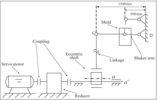
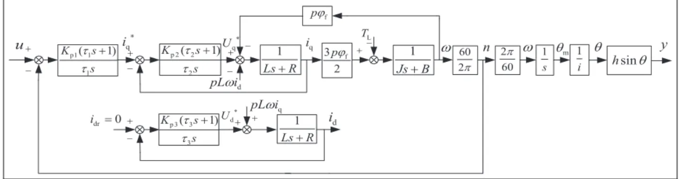
Figure 2 shows the structure diagram of oscillation platform of continuous casting mold driven by servo motor composed of servo motor, coupling, reducer, eccentric shaft, linkage, mold, shaker arm, and so on. The control structure is shown in Figure 3. The servo motor speed system is connected with mechanical trans-mission parts through the reducer.
In Figure 3, the given speed of servo motornris the system input and the displacement of mold Sm is the system output. The rest physical parameters are defined as follows: nis the actual motor speed, vis the motor angular velocity,umis the motor output angular displa-cement,uis the angular displacement of eccentric shaft, and Se is the vertical displacement of eccentric shaft. The mathematical models of servo motor speed system and mechanism transmission parts are respectively established below.
Modeling for oscillation platform of
continuous casting mold driven by servo
motor
Modeling of the servo motor system and parameter
identification
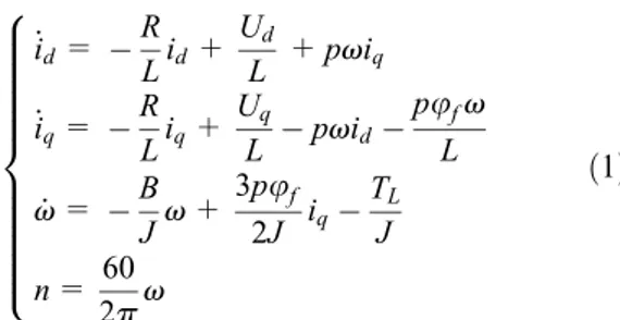
According to the vector control principle, in the dq
coordinate axis (direct axis and quadrature axis), the mathematical model of permanent magnet synchronous motor is expressed as
_
id= R
Lid+ Ud
L +pviq _
iq= R Liq+
Uq
L pvid pufv
L
_
v= B
Jv+
3pu
f
2J iq
TL J
n= 60 2pv 8 > > > > > > > > > > < > > > > > > > > > > : ð1Þ
where Ud and Uq are, respectively, the stator voltage components on dq axis (V); id and iq are, respec-tively, the stator current components ondqaxis (A); Lis the stator inductance ondqaxis (mH);Ris the stator resistance (O); uf is the permanent magnet flux
linkage (Wb); p is the number of pole pairs;J is the total moment of inertia (including motor itself and oscillation platform weight on motor shaft) (kg m2
);B is the viscous friction coefficient (Nms=rad); andTL is the load torque (N m).
The parameters of servo motor are provided in Table 1. Moment of inertia of the motor itself is 0:0625kg m2. According to KT=3pu
f=2, uf is
calcu-lated to be0:704Wb.
The identification process of parametersJandB is described below.
The motor torque equation is expressed as
KTiqTLBv=Jdv
dt ð2Þ
The characteristic curves of load torque are basically the same at two similar rotation speeds. Therefore, equation (2) can be transformed into equation (3)
KTDiq(k) =JDv(_ k) +BDv(k) +e(k) ð3Þ
where Diq(k) =i1q(k)i2q(k), Dv(_ k) =v1(_ k) v2(_ k),
andDv(k) =v1(k)v2(k) are, respectively, the current difference, angular acceleration difference, and angular
speed difference between two similar speeds.
Z=½KTDiq(1),KTDiq(2),. . .,KTDiq(N)T is defined as
the input measured value vector,
f= Dv(_ 1),Dv(_ 2),. . .,Dv(_ N) Dv(1),Dv(2),. . .,Dv(N)
is defined as the
para-meter measured value vector,X= (J,B)T is defined as the parameter vector to be identified.
Then, equation (3) is converted into equation (4)
Z=fTX+e ð4Þ
According to the least square estimation theory, the estimated values ofJandBare
^
X= (fTf)1fTZ ð5Þ
The expected speed of motor is expressed as
Figure 2. Structure diagram of oscillation platform of continuous casting mold driven by servo motor.
Figure 3. Control structure of the oscillation platform of continuous casting mold driven by servo motor.
Table 1. Parameters of servo motor.
Technical parameters Values Units
Rated power (PN) 20.4 kW
Rated current (IN) 45 A
Rated speed (nN) 1500 r=min
Stator inductance (L) 4.6 mH
Stator resistance (R) 0.14 O
Torque current ratio (KT) 3.17 Nm=A
nr(t) =60iv0
2p (1Acos (v0t)) ð6Þ
where reduction ratioi=5:1145;v0=2pf=60;fis the oscillation frequency of mold and varies from 0 to 200
(times/min);A= pa
2sin (p 2(
1+a)), whereais the wave-form deviation rate and varies from 20.4 to + 0.4. Whena=0(A=0), the mold is sinusoidal oscillation; when a6¼0(A6¼0), the mold is non-sinusoidal oscillation.
The parameter identification process is introduced as follows:
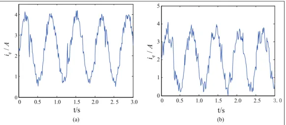
1. Viscous friction coefficient can be calculated with the motor current (current ofqaxis) data (shown in Figure 4) of two similar constant speed (sinusoidal oscillation, f=90times=min andf =120times=min). The sampling period is 0.004 s; total sampling time is 3 s; and the
sampling number is N=750. According to equation (5), the identification value of viscous friction coefficient isB=0:0706Nms=rad. 2. On the basis of viscous friction coefficient value,
total moment of inertia is calculated by motor current data (shown as Figure 5) of two similar time-varying speed (non-sinusoidal oscillation,
f =90times=min and f =95times=min). The sampling period is 0.004 s; total sampling time is 3 s; sampling number is N=750. Based on equation (5), the identification value of total moment of inertia isJ=0:1110kg m2.
3. The estimated value of load torque TL can be
calculated with motor current according to equation (2) after the calculation of J and B. Whenf =90times=min, the estimated value of load torqueTL is5:389sin (3pt) +3:889N m in
sinusoidal oscillation and TL is
7:925sin (3ptAsin (3pt)) +5:158N m in non-sinusoidal oscillation. Whenf=120times=min, Figure 4. Motor currents under two similar constant speeds: (a)nr=460:305 r=minf=90 times=minand (b)nr=485:877 r=min f=95 times=min.
the estimated value of load torque TL is 6.4985
sin (4pt) +5:1335N m in sinusoidal oscillation, and TL is 12.2045 sin (4pt Asin (4pt)) +
6:0845N m in non-sinusoidal oscillation.
The controllers of motor speed,qaxis current andd axis current, are proportional–integral (PI) controllers (Siemens S120). The control type isid= 0 and the con-trol relationships are
iq=Kp1 e1+ 1
t1 ðt
0
e1dt 0
@
1
A
Uq=Kp2 e2+ 1
t2 ðt
0
e2dt 0
@
1
A
Ud=Kp3 e3+ 1
t3 ðt
0
e3dt 0
@
1
A
ð7Þ
where e1=nrn; e2=iqriq; e2=iqriq; e1, e2, ande3are the errors of speed,qaxis current anddaxis current, respectively;Kp1,Kp2, andKp3 are the propor-tional coefficients of speed, q axis current and d axis current controllers, respectively;t1,t2, andt3are inte-gration time constant of speed,qaxis current anddaxis current controllers, respectively;iqrandidrare the given values ofqaxis current anddaxis current, respectively;
idr=0.
By parameter self-tuning of servo motor controller S120, the control parameters are obtained (Table 2).
Nonlinear model of mechanical transmission parts
Mechanical transmission parts mainly include eccentric shaft and linkage oscillation platform. Models of mechanical transmission parts are established as follows.
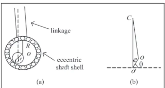
Eccentric shaft and linkage structure are shown in Figure 6(a).Ois the center of outer circle, andO9is the center of inner circle. The simplified principle diagram is shown in Figure 6(b). The eccentric distance OO9 is
e=9mm and the linkage distanceOC=573mm. In Figure 6(b), the angle between eccentric distance
OO9 and horizontal dotted line is u. Point O
anticlockwise rotates with circle center O9, and the radius isOO9. Considering thatOC is far longer than
OO9, the vertical displacement of PointC(namely, the vertical displacement of eccentric shaft Se) is approxi-mately equal to displacement of PointO. According to the projection relation, the vertical displacement of PointOis
Se=esinu ð8Þ
For the mold oscillation platform, the mold lies between Point C and Point D, and Point C performs approximately circular motion relative to the fixed PointD. According to the leverage principle, the displa-cement of mold is approximately proportional to the displacement of PointC. In Figure 1, the horizontal dis-tance between PointC and PointDis about 1500mm and the horizontal distance from the mold center to Point D is about500mm. Then, the vertical displace-ment of the mold is
Sm=kSe=kesinu=hsinu ð9Þ
where the approximate proportion coefficient is
k= (500=1500) =1=3;h=ke=3mm is the amplitude of oscillation platform of continuous casting mold.
Nonlinear model of continuous casting mold platform
The system input is u (generally corresponding to nr)
and the output isy=Sm=hsinu, indicating the non-linear relationship. The mathematical model of contin-uous casting mold oscillation platform driven by servo motor is deduced on the basis of servo motor speed sys-tem model and mechanical transmission model. The structure diagram of the model is shown in Figure 7.
Simulation experiments and error
analyses
Simulation experiments
In order to verify the model, we adopted the same sev-eral typical input signals in the mathematical model and actual system, and analyzed the output curves.
Table 2. Control parameters of servo motor controller S120.
Control parameters Values Units
Kp1 0.408 A=r=min
t1 43.2 ms
Kp2 12.982 V=A
t2 2 ms
Kp3 12.982 V=A
t3 2 ms
First, we conducted relevant experiments with the oscillation platform of continuous casting mold in the laboratory. We developed the data acquisition program in the PC equipped with Siemens Step7 software, and used WinCC to inquire and monitor data. We acquired the mold displacement to PLC with displacement trans-ducer and uploaded the data to PC for processing. Different motor speeds were set via the input terminal of actual system (the input signal is constant speed and time-varying speed). Then, we collected the data and obtained the curves of mold displacement at the output terminal.
Then, we used MATLAB/Simulink tools to conduct simulation. The same expected speed was adopted in the actual system and experimental model. The mold displacement was obtained with the model established in the article (simulation time was 3 s and the step size was 0.004 s).
The given displacement waveform function devel-oped by DEMAG corporation is expressed as
S=hsin ((vt)Asin (vt)) ð10Þ
Figure 8 shows the output curves of the model and actual system under the constant speed (f= 90 times/ min and f =120times=min, respectively). The wave-form deviation rateais 0.
Figure 9 shows the output curves of model and actual system under the time-varying speed (f = 90 times/min and f =120times=min, respectively). The waveform deviation rateais 0.24.
As shown in Figure 8 and 9, the output curves of the simulation model and actual system are almost coinci-dent with each other and show the better fitting results, which indicates that the established mathematical model in this article is close to the actual system.
Error analyses
The model error is discussed below. The error curves (Figures 10 and 11), respectively, corresponds to the curves in Figures 8 and 9. Relative errorEis defined as
Figure 7. Structure diagram of continuous casting mold vibration platform driven by servo motor.
Figure 8. Output curves of the model and actual system under the constant speed: (a)f=90 times=min and (b)
Figure 9. Output curves of the model and actual system under the time-varying speed: (a)f=90 times=min and (b)
f=120 times=min.
Figure 10. Error curves under the constant speed: (a)f=90 times=min and (b)f=120 times=min.
E= ffiffiffiffiffiffiffiffiffiffiffiffiffiffiffiffiffiffi PN 1 e2 N N s ffiffiffiffiffiffiffiffiffiffiffiffiffiffiffiffiffiffi PN 1 y2 N N s ð11Þ
whereeN is the error between model output and actual system output;yN is the model output value.
In the error curves, we can conclude that the model error is within 5%. The higher the frequency, the larger the error, because the higher frequency has the strong impact on the system response. The error analyses indi-cate that the established model in the article is reason-able and accurate.
Conclusion
1. With the oscillation platform of continuous casting mold driven by servo motor in the laboratory, an entire nonlinear system model,
including servo motor speed system and
mechanical transmission part, is established. Meanwhile, the viscous friction coefficient, moment of inertia, and load torque are identified.
2. Under the same input signal, the simulation output curves coincide with the actual output curves well, indicating the effectiveness of the established model.
3. The model error is less than 5%, indicating the effectiveness of the model.
Declaration of conflicting interests
The author(s) declared no potential conflicts of interest with respect to the research, authorship, and/or publication of this article.
Funding
The author(s) disclosed receipt of the following financial sup-port for the research, authorship, and/or publication of this article: Item sponsored by the Natural Science Foundation of China and Baosteel Group Co., Ltd. (grant no. U1260203); Natural Science Foundation of Hebei Province (grant nos. F2015203400 and F2016203263); Doctor Foundation of Yanshan University (grant no. B960); the Cultivation Program Project for Leading Talent of innovation team in Colleges and universities of Hebei Province (grant no. LJRC013).
References
1. Cai KK.Continuous casting mold. Beijing, China: Metal-lurgical Industry Press, 2008 (in Chinese).
2. Yin RY. Development of continuous casting in China in the 21st century.J Iron Steel Res Int2008; 15: 1–12. 3. Li XK and Zhang DM.Vibration technique of continuous
casting mold. Beijing, China: Metallurgical Industry Press, 2000 (in Chinese).
4. Guo LL, Tian Y, Yao M, et al. Temperature distribution and dynamic control of secondary cooling in slab contin-uous casting.Int J Min Met Mater2009; 16: 626–631. 5. Wang XD, Yao M, Zhang L, et al. Optimization of
oscil-lation model for slab continuous casting mould based on mould friction measurements in plant trial.J Iron Steel Res Int2013; 20: 13–20.
6. Zhang XZ, Zhu HT, Tieu AK, et al. An investigation of mechanical non-sinusoidal oscillation of continuous cast-ing mold.Adv Mat Res2011; 264–265: 337–342.
7. Zhang LP, Li XK, Yao YF, et al. Study on cascaded whole-leaf spring oscillation mechanism for mould in continuous casting.Ironmak Steelmak2010; 37: 204–210. 8. Li W, Zhang Y, Yu L, et al. Mold non-sinusoidal oscil-lating mode analyse and control of continuous casting machine. In: Proceeding of the 2009 IEEE 9th interna-tional conference, Beijing, China, 16–19 August 2009, pp.2–567. New York: IEEE.
9. Gan Y, Tang HW and Chou ST. The role of continuous casting in steel production process and introduction of the modern continuous casting technology. Sci China Press2008; 38: 1384–1390 (in Chinese).
10. Zhang XZ, Zheng XR, Liu QG, et al. Investigation and application of non-sinusoidal oscillation technique of mold.J Iron Steel Res Int2013; 20: 19–24.
11. Liu DW and Ren TZ. Research on non-sinusoidal vibra-tion of mold driven by non-circular gears.Chin J Mech Eng2013; 24: 327–330 (in Chinese).
12. Zhang LP, Li XK and Yang HP. Non-sinusoidal wave and process parameters of anti-parallel four-bar linkage.
Chin J Mech Eng2009; 45: 301–306 (in Chinese). 13. Li XK, Zhang LP, Yang LD, et al. Dynamics study on
new non-sinusoidal oscillation system of mold. J Iron Steel Res Int2008; 15: 517–522.
14. Fang YM, Jiao XH and Zhuang KY. Design of control system for continuous casting mold vibration driven by hydraulic servo.Metall Ind Autom2000; 24: 43–45. 15. Kang GP, Shin G and Kang CG. Development of new
model of mold oscillator in continuous casting. J Mech Sci Technol2007; 21: 421–425.
16. Li XK and Fang YM.Non-sinusoidal vibration of continu-ous casting mold generating device driven by servo motor. Patent ZL200510060032.1, China, 2007.
17. Yao YY, Li XK, Fang YM, et al. Study of non-sinusoidal vibration of continuous casting mold driven by servo motor. In:Proceedings of the 4th international conference on continuous casting of steel in developing countries, Beijing, China, 4–7 November 2008, pp.558–562 (in Chinese). 18. Lin FC and Yang SM. Adaptive fuzzy logic-based
velo-city observer for servo motor drives.Mechatronics2003; 13: 229–241.
20. Meng XN and Zhu MY. Optimization of non-sinusoidal oscillation parameters for continuous casting mold with high casting speed.J Iron Steel Res Int2008; 15: 510–516. 21. Cao CZ, Yang YM and Liu T. Modeling of fuel supply system for a high-temperature high-speed wind tunnel.
Adv Mech Eng2016; 8: 1–9.