Dynamic response analysis of single-span guideway caused by
high speed maglev train
Abstract
High speed maglev is one of the most important reformations in the ground transportation systems because of its no physi-cal contact nature. This paper intends to study the dynamic response of the single-span guideway induced by moving ma-glev train. The dynamic model of the mama-glev train-guideway system is established. In this model, a maglev train consists of three vehicles and each vehicle is regarded as a multibody system with 34 degrees-of-freedom. The guideway is mod-eled as a simply supported beam. Considering the motion-dependent nature of electromagnetic forces in the maglev system, an iterative approach is presented to compute the dynamic response of a maglev train-guideway system. The histories of the train traversing the guideways are simulated and the dynamic responses of the guideway and the train vehicles are calculated. A field experiment is carried out to verify the results of the analysis. The resonant conditions of single-span guideway are analyzed. The results show that all the dynamic indexes of train-guideway system are far less than permissive values of railway and maglev system, the vertical resonant of guideways caused by periodical excita-tions of the train will not happen.
Keywords
Maglev train, guideway, dynamic response, resonant, air gap
Jin Shi∗
and Ying-Jie Wang
School of Civil Engineering, Beijing Jiaotong University, Beijing 100044 – China
Received 30 Oct 2010; In revised form 20 Jan 2011
∗Author email: [email protected]
1 INTRODUCTION
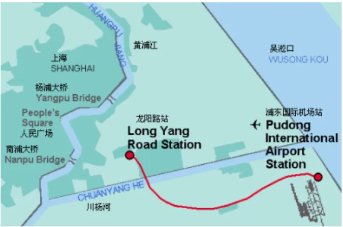
Since the 1970s, studies have been carried out on the ground transportation system based on the non-contact maglev (magnetically levitated) system that has linear motor propulsion. The maglev system has the advantages of less environmental impact, better ride quality compared to the conventional rail system. Research and development in maglev technology is being actively pursued in Europe, Japan, and the USA. Shanghai maglev system, which adopts TR08 technology, is the first commercial high speed maglev system, as shown in Figure 1.
Figure 1 Shanghai maglev route.
second has an electrodynamic suspension (EDS) that uses the repellent force induced by su-perconductors. To suspend a maglev train at a stable levitation gap (air gap) between the on-board levitation magnets and the guideway, a controllable electromagnetic field is generated in its maglev suspension system. Obviously, the response analysis of a maglev train moving on a flexible guideway is related to not only the dynamics of train-guideway interaction but also the electromagnetic control.
useful results have been brought out. Unfortunately, no further details were proposed for the resonance characteristics, especially for the high speed maglev (TR08) guideway.
In this paper, a dynamic model for analyzing the vibration of a train-guideway system is developed. Each vehicle in a maglev train is modeled with 34 degrees-of-freedom; the guideway is modeled as a simply supported beam. Based on the maglev theory, the maglev train is lifted up above the guideway with a stable levitation gap via a motion-dependent electromagnetic force. The computation of dynamic response for the train-guideway system was carried out using an iterative approach with Newmark’s method. The vibration behavior of the dynamic responses of train traversing the guideways is studied herein based on the numerical results and the experimental data. The resonant conditions of single-span guideway are analyzed. The results show that that all the dynamic indexes of train-guideway system are far less than permissive values railway and maglev system, the vertical resonant condition of guideways caused by periodical excitations of the train will not happen. The dynamic responses of the guideway and the train vehicles are analyzed in detail, which can be referenced in the determination of guideway design criterions in high speed maglev system.
2 DYNAMIC MODEL OF MAGLEV TRAIN-GUIDEWAY SYSTEM
When a high speed maglev train moves over guideway, the train and guideway form a complex dynamic interaction system. The dynamic analysis model of such a system consists of the train submodel, the guideway submodel and an assumed magnetic-guideway relationship.
Generally, the lateral vibrations of the guideway due to moving maglev train will also be smaller than the vertical motions [14]. To simplify the formulation of train-guideway interac-tion of the maglev system, only vertical train mointerac-tion is considered in this study.
2.1 Electromagnetic relationship
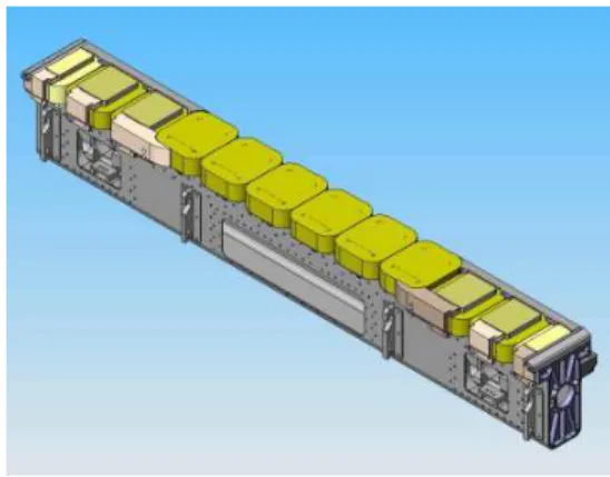
The electromagnetic interaction and the simulation of electromagnetic force are key factors between train and guideways, which are closely related to active control mechanism. The structure of suspension magnet is shown in Figure 2. There are 12 poles per suspension magnet, 6 of which are connected into a group. The interval of poles per suspension magnet is 0.258m. Air gap measurement units are installed at the two ends of the suspension magnet. The suspension magnet control units receive the air gap signals, process the signals by the suspension control unit, and then arises the electromagnetic force which suspends maglev trains.
Figure 2 Structure of suspension magnet. Figure 3 Electromagnetic suspension sys-tem.
F(i, c)= µ0N
2 A
4 [
i(t) c(t)]
2
(1)
where z(t) is the absolute position of the suspended magnet, ¨z(t) is its absolute vertical acceleration at any instance of time t, c(t) is magnetic air gap, v(t) is the displacement of guideway, i(t) is electrical circuit, N is the number of turns in the magnet winding, A is the pole face area, µ0is air permeability.
The current control laws can be given as [3, 7]
∆i=kp∆c+kv∆z˙ˆ +kaz¨ (2)
where kp,kv and ka are the feedback gains corresponding to the air gap change, the velocity and the acceleration of the magnet.
2.2 Train model
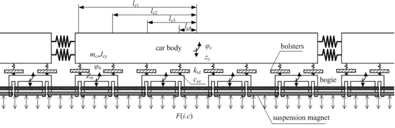
The dynamic model of train with secondary spring multi-body and multi-DOF is considered when analysis of train-guideway coupling vibration is performed. The car body is rigid and has a uniform mass. The center of mass is consistent with that of the inertia. The train model consists of several vehicles, which is a complicate multi-degree system composed of a car body, four bogies, eight bolsters, eight suspension magnets, and the spring-dashpot suspensions between the four components, as shown in Figure 4. To simplify the analysis whilst retaining sufficient accuracy, the following assumptions are used in modeling the train in this study:
1. The car-body, bogies, bolsters and magnets in each vehicle are regarded as rigid compo-nents.
2. The connections between a bogie and magnets are characterized as linear springs and viscous dashpots of the primary suspension system. The spring stiffness and damping coefficients of thejth bogie of theith vehicle are denoted askv
3. The connections between the car-body and bogies are characterized as linear springs and viscous dashpots of the secondary suspension in vertical direction (kv
2ij and cv2ij). 4. The connections between the bolsters and bogies are characterized as linear springs and
viscous dashpots of the suspension in vertical direction (kv
bij and c v bij).
With the above assumptions, the ith vehicle body has two degrees of freedom (dofs) to be considered. They are designated by vertical zci and pitching ϕci movements. The jth bogie on the ith vehicle has two dofs: vertical zxf jij and pitching ϕxf jij movements. For the lth bolster on thejth bogie andith vehicle, only one dof are considered: verticalzyzij movements. For the jth magnet on ith vehicle, two dofs are considered: vertical cctij and pitching ϕctij movements. So the idealized model for a High speed maglev vehicle can be described as 34 dofs, as shown in Figure 4.
Figure 4 Train dynamic model.
The equation of motion for the ith vehicle can be thus expressed as:
⎡⎢ ⎢⎢ ⎢⎢ ⎢⎢ ⎣
Mci 0 0 0
0 Myzi 0 0
0 0 Mxf ji 0
0 0 0 Mcti
⎤⎥ ⎥⎥ ⎥⎥ ⎥⎥ ⎦ + ⎡⎢ ⎢⎢ ⎢⎢ ⎢⎢ ⎣ ¨ vci ¨ vyzi ¨ vxf ji ¨ vcti ⎤⎥ ⎥⎥ ⎥⎥ ⎥⎥ ⎦ + ⎡⎢ ⎢⎢ ⎢⎢ ⎢⎢ ⎣
Cci Ccyzi 0 0
Cyzci Cyzi Cyzxf ji 0 0 Cxf jyzi Cxf ji Cxf jcti
0 0 Cctxf ji Ccti
⎤⎥ ⎥⎥ ⎥⎥ ⎥⎥ ⎦ ⎡⎢ ⎢⎢ ⎢⎢ ⎢⎢ ⎣ ˙ vci ˙ vyzi ˙ vxf ji ˙ vcti ⎤⎥ ⎥⎥ ⎥⎥ ⎥⎥ ⎦ + + ⎡⎢ ⎢⎢ ⎢⎢ ⎢⎢ ⎣
Kci Kcyzi 0 0
Kyzci Kyzi Kyzxf ji 0 0 Kxf jyzi Kxf ji Kxf jcti
0 0 Kctxf ji Kcti
⎤⎥ ⎥⎥ ⎥⎥ ⎥⎥ ⎦ + ⎡⎢ ⎢⎢ ⎢⎢ ⎢⎢ ⎣ vci vyzi vxf ji
vcti ⎤⎥ ⎥⎥ ⎥⎥ ⎥⎥ ⎦ = ⎡⎢ ⎢⎢ ⎢⎢ ⎢⎢ ⎣ 0 0 0 Fcti ⎤⎥ ⎥⎥ ⎥⎥ ⎥⎥ ⎦ (3)
Fxf i=−
12
∑
j=1
Γ( ∆i+I0 c0+∆cj)
2
(4)
Mxf i=
6
∑
j=1
lpjΓ( ∆i+I0 c0+∆cj)
2
−
12
∑
j=7
lpjΓ( ∆i+I0 c0+∆cj)
2
(5)
where Fxf i, Mxf i represent vertical and pitching load of suspension magnets, Γ is magnetic constant, ∆iis current change of control point,I0is normal current,c0is normal air gap, ∆cj is air gap change of control point,lpj is distance between center of magnet and control point.
2.3 Guideway model
A guideway consists mainly of guideway deck, beam and anchorages. The elastic effects of the track system are also neglected. The guideway is modeled as a three-dimensional system using the finite element method. The equation of motion for the guideway can be thus expressed as:
MbbXb¨ +CbbXb˙ +KbbXb=Fb (6)
whereMbb,Cbb,Kbband are the mass, damping and stiffness matrices of the guideway; ¨Xb, ˙Xb and Xb are the acceleration, velocity and displacement vectors of the guideway, respectively, and Fb is the force vector, consisting of two parts:
Fb=Fe+Fbv
where Fe is the vector of external forces (such as wind forces) acting on the nodes of the guideway model, andFbv is the vector of forces from the magnets of a train on the guideway. This study concerns the dynamic interaction between the suspension guideway and train, and no external excitations such as wind or earthquake are considered. This study applies the mode superposition method to the guideway only [10]. The number of mode shapes of the guideway deck taken into account in the computation should be large enough to include the effects of both the global deformation of the guideway and the local deformation of the structural elements supporting the track. This decision may be made through a convergent study of the effects of the number of mode shapes or through a comparison with the measure-ment data. The mode shape between the deck nodes obtained from the eigenvalue analysis is determined using the Lagrange interpolation.
Let ϕnv(x) denote, the values of the vertical components of the nth guideway mode at the position of the jth magnet in the ith vehicle, and let qn be the generalized co-ordinate of thenth mode. The displacement responses of the guideway deck at the same position can be expressed as
Zkdz =
Nb ∑
n=1
where Nb is the number of mode shapes. If the mode shapes of the whole guideway are normalized based on ϕT
nmϕn=1, the equation of motion of the guideway deck related to the nth mode can be derived as
¨
qn+2ξnωnqn˙ +ω2nqn=Fn (8)
where ξn and ωn are, respectively, the damping ratio and the circular frequency of the nth mode of the guideway, andFn is the nth generalized force.
Fbv is the vector of forces from the magnets of a train on the guideway, the forces can be thus expressed as
Fbv =
N
∑
i=1 8
∑
j=1
Fnij (9)
where Fnij is the nth generalized force from the jth magnet of theith vehicle,
Fnij=ϕnv(xk)Fvij (10)
The expressions for the forces Fvij can be found in equation (4).
2.4 Applications of the iterative approach
Substituting equations (4) and (5) into equation (3) and also substituting equations (9) and (10) into equation (8), and then carrying out some manipulation, one can derive the coupled equations of motion for the train-guideway system as follows:
[ Mvv0 Mbb0 ] { XbXv¨¨ }+[ Cvv0 Cbb0 ] {
˙ Xv
˙
Xb }+[
Kvv 0
0 Kbb ] {
Xv Xb }={
Fvb
Fbv } (11)
Figure 5 The flow chart for dynamic analysis.
The separated iterative steps are listed as follows:
Stage 1: The vector of displacement, velocity and acceleration at time stept for train system and guideway system are obtained.
Stage 2: Compute
Sb=Mbb(aoXt
b+a2X˙ t b+a3X¨
t
b)+Cbb(a1X t b+a4X˙
t b+a5C¨
t
b) (12)
Sv=Mvv(a0Xvt+a2X˙vt+a3X¨vt)+Cvv(a1Xvt+a4X˙vt+a5X¨vt) (13)
where
a0= 1
α∆t2, a1= β
α∆t, a2= 1 α∆t
a3= 1
2α−1, a4=
β
α−1, a5= ∆t
2 ( β α−2)
a6=(1−β)∆t, a7=β∆t,
αand β are Newmark parameters. Whenα=0.25, β=0.25, solution of Newmark integration
method is unconditionally stable.
Stage 3: Start the 1st iteration, predict Xt+∆t b =X
t
b and X t+∆t v =Xvt Stage 4: Calculate ˙Xt+∆t
b , ¨X t+∆t b , ˙X
t+∆t
v and ¨Xt
+∆t
v by means of equation (14-17)
˙ Xt+∆t
b =X˙ t b+a6X¨
t b+a7X¨
t+∆t
b (14)
¨ Xt+∆t
b =a0(X t+∆t b −X
t
b)−a2X˙ t b−a3X¨
t
b (15)
˙ Xt+∆t
v =X˙ t v+a6X¨
t v+a7X¨
t+∆t
v (16)
¨ Xt+∆t
v =a0(X t+∆t v −X
t
v)−a2X˙ t v−a3X¨
t
v (17)
Stage 5: Calculate Fvb by means of equation (4) and (5). Stage 6: ComputeXt+∆t
v
(Kvv+α0Mvv+a1Cvv)Xt
+∆t
v =Fvb (18)
Stage 7: Calculate ˙Xt+∆t
v and ¨Xt
+∆t
v by means of equation (16) and (17) Stage 8: Calculate Fbv by means of equation (9). Compute Xt+∆t
b according to equation (19)
(Kbb+a0Mbb+a1Cbb)xt+∆t
b =Fbv (19)
Stage 9: Check convergence of the solution. Compute
∥xt+∆t
b (k+1)−x t b(k)∥
∥xt+∆t
b (k+1)∥
≤ε (20)
where εis specified tolerance.
If convergence criterion (20) is not satisfied, go to stage 10. If it is satisfied, turn to stage 1 and enter the next time step.
Stage 10: Go back to stage 4, continue the next iteration.
3 CASE STUDY
3.1 Guideways and test train
ANSYS software was employed in establishing the finite element model of the 24.768m guideway. The natural vibration properties of the guideway were analyzed and there are 40 frequencies and mode shapes altogether obtained for each span guideway, and were included in the calculation. The calculated natural frequencies of the first 8 modes from the FEM models are listed in Table 1.
Figure 6 The cross sectional shape of the
beams. Figure 7 Constraint condition of bearing. Table 1 The natural frequencies of the 1st-8th mode of the single beam.
mode 1 2 3 4 5 6 7 8
Frequency/Hz 5.80 7.96 12.95 18.50 25.45 30.15 35.42 52.75
Description∗
H V L H H V H L
∗H = horizontal, V = vertical, L = longitudinal
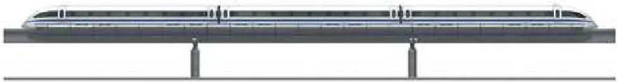
The train model used in this case study is a test train composed of three passenger coach (TR08), as illustrated in Figure 8. The main parameters of the train are listed in Table 2.
Figure 8 TR08 high speed maglev train.
To validate the calculated results and the practicability of the analysis procedure, the field experiment was carried out for the guideways and the test train. In the course of the experiment, the displacements and accelerations of the guideway and the accelerations of the test car-body were recorded simultaneously while the train moved on the guideway. The train speeds in the experiment ranged from 0 to 430 km/h.
3.2 Calculation results and their comparisons to experimental data
Table 2 Train parameters.
Mc the total weight of car body 39000 kg Mxf j the total weight of bogies 660 kg Mct the total weight of magnet 603 kg kv
1ij The spring stiffness of the primary suspension system 2.7×10
7
N/m/s
cv1ij The damping of the primary suspension system 5000 N/m/s kv
2ij The spring stiffness of the secondary suspension system 1.9×10
5 N/m
cv2ij The damping of the secondary suspension system 5000 N/m/s
2lc1 Full vehicle length 22 m 2lc4 magnet length 3.096 m
A the pole face area 356 cm2
N the number of turns in the magnet winding 300
µ0 air permeability 4πe-7 H/m
c(t) magnetic air gap 0.01 m
kp feedback gains corresponding to the air gap change 6000 kv feedback gains corresponding to the velocity 60 ka feedback gains corresponding to and the acceleration of the magnet 1
measured data of impact factor and vehicle accelerations when maglev car runs on 24m-length single span guideway. Impact factor is defined as the ratio of the maximum dynamic to the maximum static deflection of the beam under the same load. The above comparisons reflect that the calculated results are in agreement with measured results.
Figure 9 Comparison of impact factor. Figure 10 Comparison of vehicle accelera-tions.
3.3 Response of guideway
in the Germany maglev code. It is also found that the amplitude of acceleration changes from -1.1m/s2
to 0.6m/s2
and its maximum value is also smaller than the allowable value of 0.35g specified in the Chinese railway code [6].
(a) Displacement (b) Acceleration
Figure 11 Dynamic response of mid-span guideway(v=430km/h).
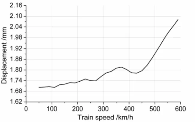
Figure 12 is the distribution of the maximum mid-span displacements versus train speed. The results show that there is no resonant train speed associated with a peak mid-span dis-placement of the guideway. The mid-span disdis-placements increase when the train speeds become higher. This is because the uniform distributed forces of the train vehicles represent the main loading for the guideway response.
Figure 12 Mid-span displacements versus train speed.
3.4 Response of train
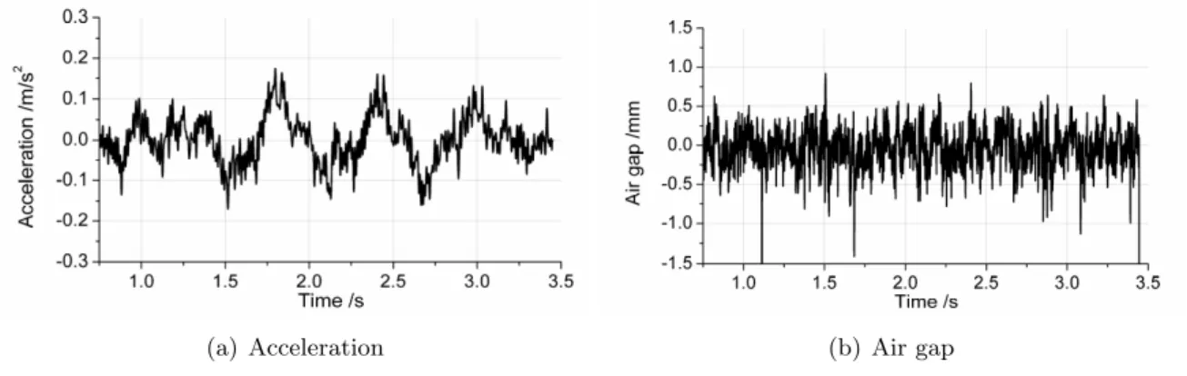
Figure 13(a) and 13(b) are the calculated time histories of the vertical car-body accelerations and air gap at the speed of 430 km/h. The maximum acceleration responses in vertical directions are well below the upper limit of 0.13g (1.28m/s2
(a) Acceleration (b) Air gap
Figure 13 Dynamic response of train (v=430km/h).
Figure 14 shows the distributions of the car-body accelerations versus train speed when the train traverses the guideways. The calculated results show the main trend that the car-body accelerations become greater with the increase of train speed. It is seen that the train responses increase significantly with the train velocityv>300 km/h.
Figure 14 The car-body accelerations versus train speed.
3.5 Resonance response of a flexible guideway
3.5.1 Resonance mechanism induced by moving loads
The first resonant condition of guideway under moving loads can be described as [4, 11]:
Vbr= 3.6fbndv
i (n=1,2,3, . . .; i=1,2,3, . . .) (21)
Equation (13) indicates that when a train moves on the guideway at speedVbr, the regularly intervals of the moving loads may produce periodical dynamic actions on the guideway with the loading perioddv/Vbr. The guideway resonance occurs when the loading period is close to thenth natural vibration period of the guideway. The first resonant condition of guideway is determined by the time of the load traveling through the distance dv.
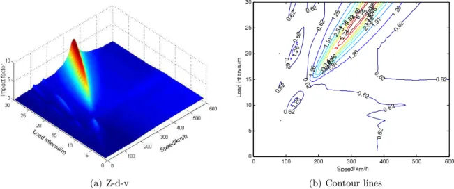
The maglev train loads act on the guideways in the form of rows of load points at the control points. The author studies the single guideway resonance response in case of N moving concentrated forces whose spacing intervals are dv. The moving concentrated force is 215.6 kN, the span of the single guideway is 24m, and the density is 34088kg/m, EI =2.5e10Nm2,
the damping ratio is 0.025. The simulation results of impact factor are shown in Figure 15. The coefficient of the vertical resonance band decrease rapidly along with the decreasing of load interval (smaller than 16m). When the load interval is small enough, the resonance will not happen. The load interval of maglev train, which is 0.258m, is so small that obvious peaks won’t appear when the speed is under 600km/h. It can be concluded that the first vertical resonant condition of guideways caused by periodical excitations of the moving concentrated load series will not happen.
(a) Z-d-v (b) Contour lines
Figure 15 Effects of moving load space and velocity on the maximum midspan displacement of guideway. The second resonant condition of guideway under moving loads can be described as:
Vbr=
7.2fbnLb
n (n=1,2,3, . . .) (22)
where Lb is the length of the guideway span (m).
The guideway resonance occurs when the time of the train’s traveling through the guideway equals to half orn times of the natural vibration period of the guideway. The second resonance is determined by the loading rate of the moving loads related to the guideway span.
minimum natural frequencies for the simply supported beams with 24 m spans are 7.98Hz, and the corresponding resonant train speeds estimated by equation (22) are 1295 km/h, which are far higher than the current train speeds in operation. The second resonant condition, however, is of certain significance in the resonance analysis for flexible guideways such as those with high piers.
3.5.2 Resonance analysis
Generally, the vertical resonance of the guideway is carried out for individual beams. In the dynamic analysis of the guideways on the Shanghai High speed maglev system, the dynamic interaction model of train-guideway system was used to study the resonant responses induced by the TR08 train. Figure 12 shows the simulated distribution curves of Mid-span displace-ments versus train speed for the single-span concrete guideway with 24m span. Obvious peaks of the simulated distribution curves don’t appear when the speed is under 600km/h. The simulated results in Figure 12 are in good accordance with the analysis in 3.5.1. It can be concluded that there is no resonant train speed associated with a peak mid-span displacement of the guideway.
4 CONCLUSIONS
The response of the single-span concrete guideway induced by moving maglev train is investi-gated in this paper. The following conclusions have been drawn from the numerical calculations and the field tests:
1. The dynamic model of the maglev train-guideway system and the computer simulator solution of the dynamic responses of the train and guideway can elucidate the main vibration behavior of the high speed maglev train and the single-span guideway. The calculated results agree well with those obtained in the field tests.
2. All the dynamic indexes of the single-span guideway caused by high speed maglev train are far less than permissive values, and the gap change is less than 2mm-safety value.
3. The midspan vertical displacement of guidway increases gradually with the increase of maglev train speed, and the vertical displacement mainly controlled by gravity loading; there is no resonant train speed associated with a peak mid-span displacement of the guideway; The train responses increase significantly with the train velocityv>300 km/h.
References
[1] Y. Cai and S.S. Chen. Dynamic characteristics of magnetically levitated vehicle systems.Applied Mechanics Reviews, 50(11):647–670, 1997.
[2] L. Fr´yba. Vibration of solids and structures under moving loads. Thomas Telford Ltd, London, UK, 2nd edition, 1999.
[3] R.M. Goodall. On the robustness of flux feedback control for electromagnetic maglev controller. In The 16th International Conference on Magnetically Levitated Systems and Linear Drive, pages 197–202, Rio de Janeiro, Brazil, 2000.
[4] S.H. Ju and H.T. Lin. Resonance characteristics of high-speed trains passing simply supported bridges. Journal of Sound and Vibration, 267(5):1127–1141, 2003.
[5] W. Kort¨um and B.N Wormley. Dynamic interactions between traveling vehicles and guideway systems. Vehicle System Dynamic, 10:285–317, 1981.
[6] Ministry of Railways. Code for Design of High Speed Railway. China Railway Publishing House, People’s Republic of China, Beijing, 2010.
[7] P.K. Sinha. Electromagnetic Suspension Dynamics & Control. Peter Peregrinus Ltd, 1987.
[8] H.P. Wang, J. Li, and K. Zhang. Vibration analysis of the maglev guideway with the moving load.Journal of Sound and Vibration, 305:621–640, 2007.
[9] Y. J. Wang, Q. C. Wei, J. Shi, and X. Y. Long. Resonance characteristics of two-span continuous beam under moving high speed trains.Latin American Journal of Solids and Structures, 7(2):185–199, 2010.
[10] H. Xia and W.W. Guo. Lateral dynamic interaction analysis of a train-girder-pier system. Journal of Sound and Vibration, 318:927–942, 2008.
[11] H. Xia, N. Zhang, and W.W. Guo. Analysis of resonance mechanism and conditions of train-bridge system.Journal of Sound and Vibration, 297(3-5):810–822, 2006.
[12] Y. B. Yang, J. D. Yau, and Y. S. Wu.Vehicle-bridge interaction dynamics-with applications to high-speed railways. World Scientific Publishing Company, Singapore, 2004.
[13] Y.B. Yang, J.D. Yau, and L.C. Hsu. Vibration of simple beams due to trains moving at high speeds. Engineering Structures, 19(11):936–944, 1997.
[14] J.D. Yau. Vibration control of maglev vehicles traveling over a flexible guideway. Journal of sound and vibration, 321:184–200, 2009.