Metallurgical characterization and computational simulation of
a screw spike aiming to improve its performance in railways
Geraldo Lúcio de Faria, Leonardo Barbosa Godefroid, Luiz Cláudio Cândido, Thayene Oliveira Silotti
Department of Material and Metallurgical Engineering, Universidade Federal de Ouro Preto, Ouro Preto, Minas Gerais, Brazila r t i c l e
i n f o
a b s t r a c t
Article history:
Received 30 November 2015
Received in revised form 14 March 2016 Accepted 1 April 2016
Available online 6 April 2016
The screw spike is an important structural component of railroads. It is afixation component responsible for supporting the platfixation on the sleeper and guarantees the railroad stability. This component is commonly produced by hot forming processing of low carbon steels. In Brazil, this component has been often failing in service due to the increase in the transported loads by trains in last years. This work investigated the stress concentration susceptibility of this component in order to understand the effects of screw threads on the mechanical behavior of the screw spike. Chemical and microstructural analyses were performed using optical emission spectrometry and optical microscopy; tensile and hardness tests were also executed. Computational models of static loading were used to determine the stress distribution along the actual geometry of the studied screw and to understand the main causes of recurrent failures. The use of appropriate relations of Mechanics of Materials associated with computa-tional simulations allowed the proposal of some changes in the screw spike original project aiming to improve its performance in service.
© 2016 Elsevier Ltd. All rights reserved. Keywords:
Tirefond screw Stress distribution Computational simulation
1. Introduction
Economic development depends heavily on the advance of transportation means. Decreasing transportation costs while increasing efficiency and reliability may grow theflow of goods and the level of national trade, and consequently, international competitiveness[1–3].
The growth of railways is directly related to the investments in high performance engineering materials, training people, work-shops, telecommunication/signaling, and especially in the superstructure of the permanent way[1–5].
According to many authors, one of the most common problems in the permanent way, besides fatigue rail failures, is the loos-ening and the fracture of thefixation system components, which requires urgently their tightening or replacing. Many derailment accidents may have been caused by either bad or insufficientfixation. The failure of the permanent way components is respon-sible for 50% of the railway accidents, and the fasteners, such as screw spikes, are included in this context[3–7].
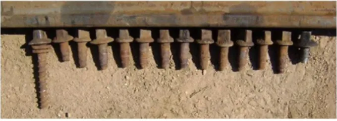
The fracture of screw spikes has become a recurrent problem in Brazilian railroads due to the increase in the transported load in the last years. The screw failures occur mainly in two situations: overload during the component installation, or in service after many hours submitted to cyclic loading. In Brazilian railroads, the second situation is the most recurrent and serious. When it happens and is not quickly detected, all the structures may be unstable and the rail lifetime decreases strongly[6].Fig. 1shows one perfect screw spike and thirteen of them failed in service. It was observed that, in general, the screw breaks down in the 2nd thread region.
Currently, screw spikes are produced by forging and hot rolling SAE1015 carbon steel bars, in accordance to the NBR 8497:08/ 2008 standard. This standard establishes the conditions for manufacturing, supplying and receiving raw materials, as well as the required mechanical characteristics for the screw spike acceptance[8,9]. However, even following the technical standard criteria, the Brazilian concessionaries have reported the increase of the failure occurrence on thisfixation element.
http://dx.doi.org/10.1016/j.engfailanal.2016.04.005
In this context, this work has as main objective to apply computational simulation as well as chemical, metallurgical and mechanical characterizations of screw spikes to understand the failure's main causes and to propose improvements in the screw manufacturing process in order to extend its lifetime without changes in steel chemical composition for economic feasibil-ity purposes.
2. Materials and methods
The structural, chemical and mechanical experimental procedures were performed in new screw spikes supplied by the same manufacturer of the failed screws used in the railroad (Fig. 2).
The chemical analysis was performed by optical emission spectroscopy. The microstructural characterization was done in an optical microscope. The tensile tests were executed at room temperature in a universal machine with 10−3s−1strain rate.
Bars of SAE1015 steel were drawn until differentfinal strains (5, 10, 15, 20 and 25%). The strained samples were machined and submitted to tensile tests in similar conditions. The yield and tensile strengths, as well as the area reduction and the total elongation were determined for each pre-strained sample. Applying these results, a strain hardening curve was built. A torsion test was also performed aiming to determine the material shear yield strength.
Subsequently, thefinite element technique was applied, using the ANSYS 14.5 software, to determine the stress distribution along the actual screw spike when loaded.
The characterization results were used as input data to the computational model. Then, the stress distribution on the screw spike subjected to a regular static load of 15 kN[4,8,9]was simulated for three different geometries: the current (to understand the recurrent failures) and two new proposed designs.
The two new geometries were proposed based on calculation models of the stress concentration factor Ktproposed by Neuber [10–20]. The determination of the stress concentration factor under normal stress loading, considering a geometry with a single
thread, was performed using Eq.(1), wheretis thread height, andris the thread root radius[10–12].
Kt¼1þ2 ffiffiffiffiffi t r: r
ð1Þ
The screw spike has a sequence of identical and equally spaced threads. Due to that, according to models based on Mechanical of Materials, a stress relief occurs at the stress concentration points. Neuber's model was used to determine the relief load coefficient (γ) by using Eq.(2)either for the actual and proposed geometries. In those models, this coefficient is a correction
factor used to calculate the geometrical stress concentration (Kt) in a screw with multiples and sequential threads, wheret=
thread height;P= distance between two threads (pitch) (Eq.(3))[10–15].
γ¼ P
πt
Tgh πt
P
ð2Þ
Kt¼1þ2
tγ
r 12
: ð3Þ
Fig. 1.In service failure of screw spikes.
Fig. 2.Screw spike.
model that considers the application of dynamic loads, such as cyclic loads, that generally promote the nucleation of fatigue cracks at these critical points. Furthermore, this model takes into account the material metallurgical characteristics. Eq.(4)was used to determine the stress concentration factor for dynamic loading (Kf), whereais a constant determined in function of the material
tensile strength and hardness[14–20].
Kf¼1þ
Kt 1
1þ ffiffiffi a r
r ð4Þ
Furthermore, Neuber proposes a stress concentration factor (Kf*), under cyclic loading, for screws with different diameters
along its body. This value was also determined by Eq.(5) [14–20].
Kf ¼ D d
2
Kf ð5Þ
3. Results and discussion
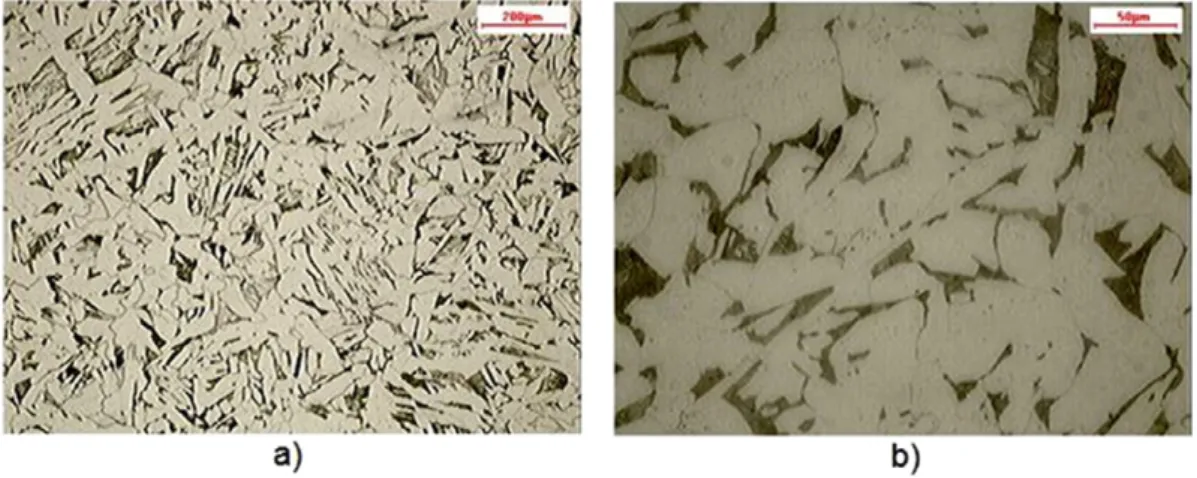
Table 1presents the chemical composition of the steel used in the actual screw manufacturing. It is possible to observe that the screw is made of a common carbon steel that meets the SAE1015 steel specifications. Microstructural analysis showed that the steel is mainly constituted of ferrite and pearlite, with a small amount of inclusions (Al2O3), normal for this kind of material.
The ferritic grains are very irregular, typical of a relatively fast cooling (dynamic air cooling).Fig. 3shows micrographs of the actual screw spikes.
Tensile tests were performed on the screw spike aiming to determine yield strength, tensile strength, total strain, and area reduction, which were 262 MPa, 449 MPa, 38% and 65%, respectively. The engineering data were mathematically processed to calculate, point by point, the real tensile-deformation curve. These data were used as the material reference in the computational model.
Fig. 4shows the strain hardening curve of the SAE1015 steel, used in the screw spike manufacturing. It can be seen that it is possible to increase the steel yield and tensile strengths by the cold pre-strain application. Therefore, a change in the manufactur-ing process may be feasible. Replacmanufactur-ing the hot rollmanufactur-ing of the screw threads by cold rollmanufactur-ing, the steel yield strength at the screw surface can significantly increase without strong ductility losses. This change in the manufacturing process may be a good opportunity to improve the raw-material performance without chemical composition changes, as initially proposed.
The current screw spike geometry was generated using the ANSYS software considering 1/4 of the geometric symmetry, followed by a discretization in hexahedral elements. A normal tensile load of 15 kN was applied on the screw head. This value was chosen taking into account the magnitude of the stress between the rail shoulders and sleeper interface (1200 N/cm2) as
well as its contact area (500 cm2)[8]. Once this shoulder is screwed by four screws to the sleeper, it is assumed that the screw
could support a tensile load of 15 kN.
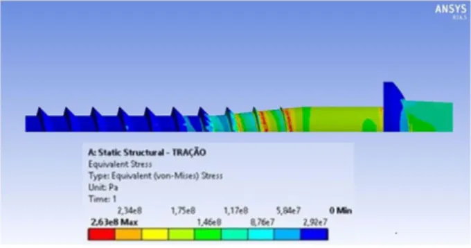
Fig. 5shows the stress distribution in the current geometry of the screw according to the model. It is possible to observe that the higher stress values were placed especially on the threads near the screw head, where the maximum stress reaches 268 MPa, which is higher than the yield strength of the used steel (262 MPa).
The area where the highest stress value was observed coincides exactly with the fractured region of most failed screws, as shown inFig. 1. Therefore, it can be concluded that this failure is occurring in this region due to overload or fatigue. The tensile load of 15 kN or greater applied to the screw may cause local plastic strain, because the material yield strength is exceeded in the second thread region. The component dynamic loading may promote a fatigue crack nucleation also in this area (highest stress concentration), leading the component to the failure.
A new screw geometry was proposed after analyzing the stress distribution on the current geometry of the screw spike. The
first proposed change was to decrease more gradually the screw diameter between the shank region and the threads.Fig. 6
illustrates (red arrow) the proposed geometry and the simulation of a normal tensile load of 15 kN applied on the screw head. The results of the computational simulation inFig. 7show that a highest tensile stress (263 MPa) was also calculated for points located at the threads near to the head of the screw, therefore without significant change in the stress state.
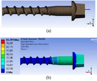
Using the Neuber model as a reference, the second proposed geometry for the screw spike was to increase the upper thread radius from the current 3 mm to 8 mm. According to Eq.(3), the greater the thread radius, the smaller the stress concentration factor. Thus, the 8 mm radius geometry has a theoretical stress concentration factor of Kt= 2.22, and stress concentration factors
for dynamic loading ofKf= 2.18 andKf* = 4.77[10–20].
Fig. 8(a) shows the discretization of the second evaluated geometry of the screw spike with 8 mm thread radius while (b) shows the analysis of the stress distribution when it was loaded by a normal load of 15 kN. The analysis of the obtained results shows a drastic decreasing of the maximum stress along the screw (84 MPa). This value is strongly lower than the SAE 1015 steel yield strength.
In order to improve the mechanical properties of the screw spike, it is possible to apply a carbon steel with a higher carbon content such as, SAE1030 steel or SAE1045 to obtain high yield strength and good ductility. There is also the possibility to apply a microalloyed steel, but the high cost makes it unfeasible for screw spike manufacturers[20–23].
Moreover, as previously discussed, the forging and rolling processes used to manufacture the screw spike can be cold performed aiming to increase its mechanical strength, as a result of strain hardening. Cold forming increases component fatigue life because it generates a compressive residual stress on component surface and increases its surface yield strength while keeping the core relatively ductile[24,25].
Fig. 4.Strain hardening curve of the SAE1015 steel; LR—tensile strength; LE—yield strength, AL—elongation; and RA—area reduction.
In this context,Table 2shows how stress concentration factors vary when geometry and mechanical properties also vary due to changes in the manufacturing process. These factors were calculated by the application of Neuber model (using as material properties input data the strain hardening curve shown inFig. 4). Geometry A was thefirst proposed (elimination of the abrupt diameter decreasing along the screw body). Geometry B was the second proposed (stress concentration factor decreasing by increasing the thread radius).
It can be seen that geometry B, without cold strain hardening, reduces drastically the concentration factors compared to the actual used geometry. Furthermore, if geometry B were combined with a 25% of cold strain of the SAE1015 steel, during the manufacturing process, higher strength and lower stress concentration factors are obtained compared to the other studied conditions.
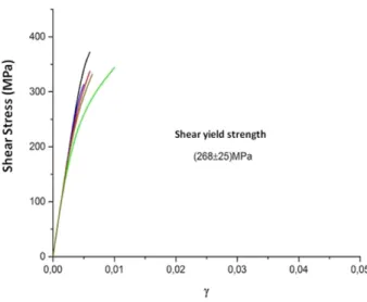
The screw spike is fastened to the wood sleeper using a torque applier machine. As there are also failures during the screw spike installation, a torsion test was applied to the SAE 1015 steel and the determined shear yield strength was 268 MPa. The shear stress–strain curve is presented in Fig.9.
Fig. 6.Thefirst proposed geometry discretized by hexahedral elements.
Fig. 7.Stress distribution on thefirst proposed geometry of screw spike. Computational simulation considering a normal tensile load of 15 kN applied on screw head.
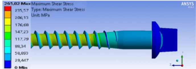
Thus, from the mathematical model built for the actually used geometry and mechanical properties of the screw, the stress distribution analysis was proposed by applying a 550 N·m torque to the screw spike head. It was observed that the highest shear stress was 265 MPa on the threads. Considering that the current screw spike has a shear yield strength of 268 MPa, it is possible to conclude that the 550 N·m torque induces a shear stress in threads that may be dangerously close to promote the component plastic strain.Fig. 10presents the computational simulation results obtained with ANSYS software.
4. Conclusions
The screw spike used in Brazilian railways and characterized in this work is manufactured by the SAE 1015 steel produced by hot metal forming. The steel microstructure is heterogeneous, typical of dynamic air cooling, and consists of ferrite and pearlite. The application of computational simulation models provided sufficient understanding of the cause of screw spikes' recurrent failures. It was concluded that the currently used geometry associated with the high service loading produces high stress values at the base of the threads, especially in the second thread region, where in an extreme case, it exceeds the yield strength of SAE1015 steel, leading to a localized plastic deformation that can fracture the screw due to either overload or fatigue.
The Neuber model was used to determine the stress concentration factors at the base of the threads for the different screw geometries proposed. A geometry that significantly reduces the stress on the base of the threads, by increasing the thread radius, has been proposed. This new geometry may improve the screw spike performance and avoid these recurrent failures without SAE1015 steel replacement.
Regarding the manufacturing process, the strain hardening curves and the stress concentration factors show that the cold rolling of the SAE1015 steel in the manufacture of screw spike threads would increase its yield strength and surface hardening, further improving performance. It is noteworthy that this process would be economically advantageous, since in addition to lower production cost, the same raw material could be maintained, without cost incensement.
The highest supported torque by the screw spike, without significant plastic strain during its installation, is 550 N·m applied to its head.
Table 2
Stress concentration factors calculated according to screw geometries and mechanical properties.
Current screw
Geometry A Geometry B
Without cold hardening
15% of cold deformation
25% of cold deformation
Without cold hardening
15% of cold deformation
25% of cold deformation
Yield strength (MPa) 449 449 620 665 449 620 665
t(mm) 4 3 3 3 4 4 4
r(mm) 3 3 3 3 8 8 8
P(mm) 12 12 12 12 12 12 12
γ 0.80 0.83 0.83 0.83 0.75 0.75 0.75
Kt 3 2.83 2.83 2.83 2.22 2.22 2.22
Kf 2.88 2.73 2.75 2.77 2.18 2.19 2.20
Kf* 6.3 5.97 6.03 6.06 4.77 4.80 4.81
Acknowledgments
The authors thank CAPES for the grant awarded to TOS in 2013 and to the VLI-FCA Company for supplying the materials.
References
[1] R.P. Fici, The Brazilian Railroads and the Recent Expansion to Central-West(PHD Thesis) Universidade Federal de São Paulo, São Paulo, 2007.
[2] M. Sánches, D. Wang, J. Briaud, C. Douglas, Typical geomechanical problems associated with railroads on shrink–swell soils, Transp. Geotech. 1 (4) (2014)
257–274.
[3] M.W. Babcock, J. Sanderson, Should shortline railroads upgrade their systems to handle heavy axle load cars? Transp. Res. E Logist. Transp. Rev. 42 (3) (2006) 149–166.
[4] L.F.M. Silva, Theoretical and Experimental Fundaments of the Railroads Mechanics and Proposition of a Maintenance System Applied to the Permanent Way(PHD Thesis) Universidade Federal do Rio de Janeiro, Rio de Janeiro, 2002.
[5] A. Ekberg, E. Kabo, Fatigue of railway wheels and rails under rolling contact and thermal loading—an overview, Wear 258 (7-8) (2005) 1288–1300. [6] L.B. Godefroid, G.L. Faria, L.C. Câdido, T.G. Viana, Failure analysis of recurrent cases of fatigue fracture in flash butt welded rails, Eng. Fail. Anal. (2015),http://dx.
doi.org/10.1016/j.engfailanal.2015.05.022.
[7] N. Ma, Z. Cai, H. Huang, D. Deng, H. Murakawa, J. Pan, Investigation of welding residual stress in flash-butt joint of U71Mn rail steel by numerical simulation and experiment, Mater. Des. (2015),http://dx.doi.org/10.1016/j.matdes.2015.08.124.
[8] Agência Nacional de Transportes Terrestres—ANTT. Evolução do Transporte Ferroviário. (acesso em 01 fev. 2014. Disponível em:http://ww.antt.gov.br). [9] NBR 8497: Metroferroviário—Tirefão, 2008.
[10] W.D. Pilkey, D.F. Pilkey, Stress Concentration Factors, John Wiley & Sons, New Jersey, 2008.
[11] D. Castagnetti, E. Dragoni, Stress Concentrations in Periodic Notches: A Critical Investigation of Neuber's Method, 52013 364–371. [12] R.L. Norton, Machine Design. An Integrated Approach, Prentice Hall, New Jersey, 2006.
[13] C. Esveld, Modern Railway Track, MRT Productions, 2001.
[14] G.H. Majzoobi, G.H. Farrahi, N. Habibi, Experimental evaluation of the effect of thread pitch on fatigue life of bolts, Int. J. Fatigue 27 (2005) 189–196. [15] W. Guo, H. Shen, H. Li, Stress intensity factors for elliptical surface cracks in round bars with different stress coefficient, Int. J. Fatigue 25 (2003) 733–741. [16] H. Neuber, Theory of Notch Stress: Principles for Exact Calculation of Strength With Reference to Structure Form and Materials, Washington, DC, USA, Office of
Technical Services, Department of Commerce, 1964.
[17] M.A. Megglioraro, A.C.Q. Miranda, J.T.P. Castro, Short crack threshold estimates to predict notch sensitivity factors in fatigue, Int. J. Fatigue 29 (2007) 2022–2031. [18] E. Dragoni, Effect of thread pitch on the fatigue strength of steel bolts, Proc. Inst. Mech. Eng. 211 (1997) 591–600.
[19] E. Dragoni, D. Castagnetti, Stress concentrations in periodic notches: a critical investigation of Neuber's method, Mater. Sci. Technol. 44 (2013) 364–371. [20] E. Fetullazade, H.K. Akyildiz, S. Saritas, Effects of the machining conditions on the strain hardening and the residual stresses at the roots of screw threads, Mater.
Des. 31 (4) (2010) 2025–2031.
[21] K. Kitayama, C.N. Tomé, E.F. Rauch, J.J. Gracio, F. Barlat, A crystallographic dislocation model for describing hardening of polycrystals during strain path changes. Application to low carbon steels, Int. J. Plast. 46 (2013) 54–69.
[22]J. Zhang, H. Ding, R.D.K. Misra, Enhanced strain hardening and microstructural characterization in a low carbon quenching and partitioning steel with partial austenization, Mater. Sci. Eng. A 636 (2015) 53–59.
[23] N. Tsuchida, T. Inoue, H. Nakano, T. Okamoto, Enhanced True Stress–True Strain Relationships due to Grain Refinement of a Low-carbon Ferrite–Pearlite Steel,
1602015 117–119.
[24] V. Llaneza, F.J. Belzunce, Study of the effects produced by shot peening on the surface of quenched and tempered steels: roughness, residual stresses and work hardening, Appl. Surf. Sci. 356 (2015) 475–485.