www.atmos-chem-phys.net/15/8459/2015/ doi:10.5194/acp-15-8459-2015
© Author(s) 2015. CC Attribution 3.0 License.
Global distributions of overlapping gravity waves in HIRDLS data
C. J. Wright1,2, S. M. Osprey3, and J. C. Gille2,4
1Centre for Space, Atmosphere and Ocean Science, University of Bath, Claverton Down, Bath, UK 2Atmospheric Chemistry Division, National Center for Atmospheric Research, Boulder, CO, USA 3Atmospheric, Oceanic and Planetary Physics, Department of Physics, University of Oxford, Oxford, UK 4Center for Limb Atmospheric Sounding, University of Colorado, Boulder, CO, USA
Correspondence to:C. J. Wright ([email protected])
Received: 17 October 2014 – Published in Atmos. Chem. Phys. Discuss.: 17 February 2015 Revised: 29 May 2015 – Accepted: 6 July 2015 – Published: 30 July 2015
Abstract. Data from the High Resolution Dynamics Limb Sounder (HIRDLS) instrument on NASA’s Aura satellite are used to investigate the relative numerical variability of ob-served gravity wave packets as a function of both horizontal and vertical wavenumber, with support from the Sounding of the Atmosphere using Broadband Emission Radiometry (SABER) instrument on TIMED. We see that these distri-butions are dominated by large vertical and small horizontal wavenumbers, and have a similar spectral form at all heights and latitudes, albeit with important differences. By dividing our observed wavenumber distribution into particular sub-species of waves, we demonstrate that these distributions exhibit significant temporal and spatial variability, and that small-scale variability associated with particular geophysi-cal phenomena such as the monsoon arises due to variations in specific parts of the observed spectrum. We further show that the well-known Andes/Antarctic Peninsula gravity wave hotspot during southern winter, home to some of the largest wave fluxes on the planet, is made up of relatively few waves, but with a significantly increased flux per wave due to their spectral characteristics. These results have implications for the modelling of gravity wave phenomena.
1 Introduction
Gravity waves (GWs) are a key component in our under-standing of the global atmospheric circulation, helping to de-termine the broad-scale structure of the middle atmosphere and driving atmospheric dynamics on all scales (e.g. Fritts, 1984; Holton et al., 1995; Nappo, 2002; Fritts and Alexander, 2003, and references therein). Vertically propagating GWs
carry a vertical flux of horizontal pseudomomentum (mo-mentum flux, MF), transferring it away from low altitudes and returning it to the mean flow at altitudes and locations far removed from the region of wave generation. Parameter-isations of these processes used for numerical weather pre-diction and climate models have significantly reduced circu-lation biases (e.g. Karoly et al., 1996; Alexander et al., 2010; Geller et al., 2013).
The propagation characteristics of GWs, such as their phase velocity and their direction, are difficult to directly measure from current almost-instantaneous satellite data. Nevertheless, these waves can often be effectively parame-terised using spatial information, such as their horizontal and vertical wavenumberskh=1/λh andkz=1/λz1. Key
pro-cesses such as Doppler shifting, critical-level wave filtering, and ducting act to redistribute wave energy and momentum in ways which are dependent on these spectral characteristics. Accordingly, a better knowledge of the wavenumber distri-bution of these signals in the real atmosphere could aid sig-nificantly in our understanding of the atmospheric system, providing necessary observational constraints for the GW pa-rameterisations which form a key component of climate and weather models (e.g. Kim et al., 2003; Song et al., 2007; Richter et al., 2010) and, perhaps more directly, in diagnos-ing the performance of current and future high-resolution
1We use this definition of wavenumber, with units of wave
models which attempt to simulate waves at the scales acces-sible to modern satellite instrumentation.
Recent advances in satellite instrumentation (e.g. Fritts and Alexander, 2003; Wu et al., 2006; Preusse et al., 2008; Alexander et al., 2010, and references therein) have made possible the direct detection and measurement of GWs on a global scale at resolutions previously unavailable, allowing for identification of their geographic distribution and their spectral characterisation. In this article, we use measure-ments from the High Resolution Dynamics Limb Sounder (HIRDLS) on NASA’s Aura satellite to produce a broad-scale assessment of the wavenumber distribution in the stratosphere and lower mesosphere throughout the calendar year 2007. Specifically, we use data derived using the Stock-well transform (ST, StockStock-well et al., 1996) as applied to at-mospheric temperature profiles; this technique has been used extensively for the detection of gravity waves in atmospheric data (e.g. Stockwell, 1999; Wang et al., 2006; Alexander et al., 2008; Wright, 2012; McDonald, 2012; France et al., 2012). Finally, we use these data to examine the variations between four “species” of gravity waves defined by their range of horizontal and vertical wavenumbers and analyse these independently, showing both similarities and differ-ences in their temporal and spatial behaviour.
Section 2 discusses the instruments used, Sect. 3 describes the analysis method, and Sect. 4 gives a brief summary of the most important limitations that apply to our results. Sec-tions 5 and 6 then discuss the observed one-dimensional and two-dimensional wave spectra in the global mean respec-tively, and Sect. 7 regional variations. Finally, Sect. 8 divides the observed wave population into species and discusses their variation.
2 Data 2.1 HIRDLS
Designed to measure high vertical resolution atmospheric ra-diance profiles, HIRDLS (Gille et al., 2003) is a 21-channel limb-scanning filter radiometer on NASA’s Aura satellite.
Shortly after launch in 2004 an optical blockage, believed to be a loosened flap of the Kapton®material lining the fore-optics section of the instrument, was found to obscure around 80 % of the viewing aperture. Consequently, major corrective work has been required to produce useful atmospheric data. Measurements of temperature, cloud, and a wide range of chemical species have now been successfully retrieved and made available for scientific analysis (Massie et al., 2007; Nardi et al., 2008; Kinnison et al., 2008; Gille et al., 2008, 2013; Khosravi et al., 2009).
One particularly productive area of research has been the detection and analysis of GWs (e.g. Alexander et al., 2008; Hoffmann and Alexander, 2009; Wang and Alexander, 2009; Wright et al., 2010, 2013; Yan et al., 2010; France et al.,
2012; Ern and Preusse, 2012). This would have been pos-sible with the original horizontal and vertical scanning mode of the instrument, but the closer along-track profile spacing made possible by the lack of horizontal scanning capabil-ity has allowed measurements to be taken at a higher hor-izontal resolution than originally planned, facilitating such research. Measurements are made in vertical profiles: around 5500 profiles are obtained per day, spaced approximately 70– 105 km apart depending on the scan direction (see Sect. 4.3) and scanning pattern used. Due to the optical blockage, mea-surements are taken at a significant horizontal angle,∼47◦, to the track of the satellite, as a result of which observa-tions cannot be made south of 62◦S and are not spatially co-located with other instruments on the Aura satellite.
V007 of the HIRDLS data set provides vertical tempera-ture profiles from the tropopause to∼80 km in altitude as a function of pressure, allowing us to produce useful gravity wave analyses at these higher altitudes. Measurements have a precision∼0.5 K throughout the lower stratosphere, increas-ing with height to∼1 K at the stratopause and 3 K or more above this, depending on latitude and season (Gille et al., 2013). Vertical resolution is∼1 km throughout the strato-sphere, smoothly declining to∼2 km above this.
Data are available from late January 2005 until March 2008, when a failure of the optical chopper terminated data collection. A variety of scanning modes were used until June 2006, after which the scanning mode remained constant until the end of the mission. Consequently, we examine here data from the calendar year 2007; this provides a complete year of data at a consistent horizontal resolution, but without biasing the results by including an additional fractional year. 2.2 SABER
In parts of this paper, we also use data derived from the Sounding of the Atmosphere using Broadband Emission Ra-diometry (SABER) instrument on NASA’s TIMED satellite to assess the methodology. A 10-channel limb-sounding in-frared radiometer, SABER, was intended primarily to mea-sure and characterise the mesosphere and lower thermo-sphere on a global scale, but also scans down into the strato-sphere, providing∼2200 vertical profiles per day with a ver-tical resolution of approximately 2 km (Mertens et al., 2009) and an along-track profile spacing alternating between∼200 and∼550 km depending on scan direction (in an equivalent manner to HIRDLS, discussed in Sect. 4.3 – see Fig. 1 of Ern et al., 2011, for a diagram illustrating the comparative scan-ning pattern of both instruments). Kinetic temperature pro-files cover the altitude range from∼15 to∼120 km (Mertens et al., 2009; Wrasse et al., 2008).
year, high northerly and southerly latitudes are only covered for 60 of every 120 days, in a 60-day on, 60-day off cycle, with coverage in the “off” hemisphere extending to 54◦and in the “on” hemisphere to 87◦. We use SABER version 1.07 temperature data for 2002–2012, with a precision of∼0.8 K (Remsberg et al., 2008); the longer period is possible due to the consistent profile-to-profile scanning pattern of the in-strument since launch, but provides a smaller total number of resolved wavelike features due to the coarser resolution of the data set.
3 Analysis
To detect gravity waves, we use the method of Alexander et al. (2008), as modified by Wright and Gille (2013). Briefly, we compute the daily mean background temperature and first seven planetary-scale wave modes at each height level using a Fourier transform in longitude separately for each 2◦ lati-tude band, and remove these from the data (Fetzer and Gille, 1994). This leaves temperature perturbation profiles from the surface to 80 km. Below clouds, the temperature data set re-laxes back to the GEOS-5 a priori data, and consequently we do not expect to detect meaningful gravity wave signals at these levels, but we include this information to provide some overage for the analysis; this may suppress detection of the longest vertical-wavelength waves in our analysis at tropical latitudes to some degree at the 20 km altitude level, and may lead to a slight low-biasing of wave amplitude at the lower altitudes of our analysis, but should not otherwise impact upon our results. We further add 20 vertical levels of zero-padding at each end of the vertical domain to reduce wraparound and Gibbs-ringing effects. We then interpolate onto a regular 1 km vertical scale, representative of the reso-lution of the instrument at most altitudes, and transform the profile using the Stockwell transform (ST, Stockwell, 1999). This returns, for each height and wavenumber considered, a phase and wave amplitude for any wavelike signals detected. For further discussion of this, see e.g. Sect. 2.2 of Alexander et al. (2008).
We next cross-multiply along-track adjacent profile pairs to compute complex co-spectra, from which we compute the co-varying temperature amplitudeT (kˆ z, z), and locate each
ˆ
T (kz, z) at which a distinct local maximum is observed in
the ST spectrum. We then apply the statistical significance test described by McDonald (2012), modified as described by Wright and Gille (2013), and require signals to be signifi-cant at the 99 % level. From this analysis we obtain, for each height level in each profile, an estimate for each statistically significant wavelike signal (hereafter simply “wave”) for the parameters Tˆ and kz. Since multiple above-noise spectral
peaks may exist in a profile at a given height, this method allows for the detection of overlapping wavelike signals, in contrast to many previous studies. For each of these signals, using the phase change between these signals1φi,i+1 and
profile separation1ri,i+1, we further compute and retain the
horizontal wavenumber
kh=
1 2π
1φi,i+1
1ri,i+1
(cycles per metre, cpm). (1) Values ofkzreturned from the analysis are quantised; these
values are “binned” into bins corresponding to each quan-tised value, and all bins are shown on all relevant figures. Values ofkh form a continuous spectrum and are binned in
all analyses into 50 bins base-10-logarithmically distributed across the range 10−7–10−5m−1. Changing the number of
bins inkh does not significantly alter the form of the
distri-bution; the value of 50 bins was chosen to provide a balance between data resolution and local data processing capabili-ties.
Finally, in some sections, we use momentum flux esti-mated from these measurements. Momentum flux is impor-tant in both the real and model worlds, both as a real-world mechanism which teleconnects sections of the atmosphere without mass transfer and in the model world as a property which when parameterised at the subgrid level helps to cor-rect for momentum and energy biases arising due to the lack of simulation of small-scale waves and related processes. This is calculated as (Ern et al., 2004)
Mi,i+1=
ρ
2
kh
kz
g
N
2 Tˆ
T
!2
, (2)
whereρis the local atmospheric density,gis the acceleration due to gravity,N is the buoyancy frequency, andT is the lo-cal mean atmospheric temperature. It should be noted that this expression only applies well under the midfrequency ap-proximation (i.e. the assumption thatN≫ ˆω≫f) for grav-ity waves, and does not take account of vertical shear or of re-flection (e.g. Sato and Dunkerton, 1997). The midfrequency approximation applies well to our data in most spectral re-gions, except for those at very high vertical and short hori-zontal wavenumbers.
(a)
HIRDLS−all
log
10(kz [cpm])
Number observed [x10
3]
20 km 30 km 40 km
50 km 60 km 70 km
−4.2 −4.1 −4 −3.9 −3.8 −3.7 −3.6 −3.5 −3.4 −3.3
0 50 100 150 200 250 300 350 400
16 14 12 10 8 6 5 4 3 2.5 2
Wavelength [km]
−4.2 −4 −3.8 −3.6 −3.4
0 100 200
(b)
SABER
log
10(kz [cpm])
Number observed [x10
3] 16 12 10 8 6 5 4 3 2.5 2
Wavelength [km]
(c)
HIRDLS−pk
log
10(kz [cpm])
Number observed [x10
3]
−4.2 −4 −3.8 −3.6 −3.4
0 100 200
16 12 10 8 6 5 4 3 2.5 2
Wavelength [km]
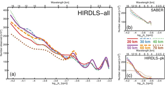
Figure 1. (a)Number of observed waves (all times, all locations), as a function of the log10vertical wavenumber. Solid coloured lines
indicate the number of observed waves at each wavenumber for six selected heights (key at centre right).(b)Equivalent results for SABER. Note that the 20 km line is omitted here due to poor data quality at this altitude.(c)Equivalent result for the HIRDLS-pk data set.
when used for other purposes; features of a large physical scale such that they would be detected in multiple profiles will inherently contribute more to area averages of physical parameters than features of a smaller physical scale, and this inherent repeated sampling to some degree therefore weights these features more strongly than smaller ones.
3.1 HIRDLS-pk
In Figs. 1 and 3, we compare our results to a data set com-puted using the same HIRDLS V007 data, but locating only the single largest-co-varying-amplitude peak at each altitude level of each profile. This reduces our data set to one al-most identical to Alexander et al. (2008), with minor differ-ences due to (i) applying the noise-comparison method of McDonald (2012), (ii) the use of a Fourier transform rather than a Stockwell transform to remove planetary-scale waves, and (iii) the data extending up to 80 km altitude. We refer to this data set as “HIRDLS-pk” and to the primary data set as “HIRDLS-all” where necessary to avoid ambiguity.
3.2 SABER
Figures 1 and 3 also compare our data to equivalent results computed using SABER. This analysis is methodologically equivalent to the main HIRDLS analysis method, with three differences: (i) due to the smaller numbers of usable profiles, we compute planetary waves based on a rolling 3-day mean of global temperature rather than individual days, (ii) data are interpolated to a 2 km vertical resolution rather than 1 km, and (iii) after Ern et al. (2011), we remove profile pairs sep-arated by more than 300 km. We refer to this data set as “SABER”.
4 Measurement limitations
Our measured results will not fully capture the true spectrum of wavelength data, due to the observational filter (Alexan-der, 1998; Preusse et al., 2000, 2008; Trinh et al., 2015) of the instrument and to other effects arising as a result of the analysis process. We discuss here the key limitations inherent in our measurements and analysis technique; Table 1 sum-marises these effects.
We describe here only the limitations applying to HIRDLS; a full description of the applicable limitations for SABER is omitted for brevity. Generally, such limitations are similar after allowing for the different instrument reso-lutions and weighting functions, and identical for the effects discussed in Sect. 4.4–4.7, with the exception of the specific boundary latitude values given in Sect. 4.4
4.1 Vertical resolution
For HIRDLS, the lower limit to measurable vertical wave-length λz in the stratosphere is ∼2 km (e.g. Wright et al.,
2011). This is imposed by the 1 km vertical resolution of the data, resulting from the radiometer channel detectors, low radiometric noise and the choice of vertical sampling (Gille et al., 2008), which result in narrow averaging ker-nels (Khosravi et al., 2009). This corresponds to an upper limit on vertical wavenumberkz=5×10⁻⁴cycles per metre
(cpm). Due to the increased vertical width of the averaging kernels at higher altitudes (Gille et al., 2013), this increases toλz∼3.5 km (decreases to 2.9×10⁻⁴cpm) at mesospheric
altitudes. We impose a lower limit ofkz=6.25×10⁻⁵cpm
(upper limit ofλz=16 km) in our analysis; the underlying
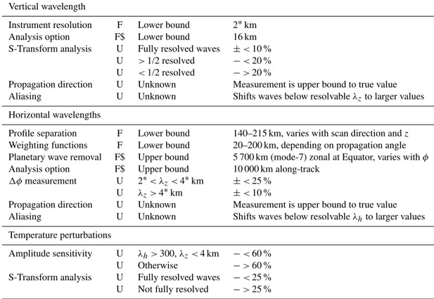
Table 1.Summary of errors in measurements due to analysis method. F indicates a fixed limit, U an uncertainty.∗indicates that the asterisked number approximately doubles above 60 km; $ indicates that this value is due to choices we have made rather than physical or methodological limitations.
Vertical wavelength
Instrument resolution F Lower bound 2∗km
Analysis option F$ Lower bound 16 km
S-Transform analysis U Fully resolved waves ±<10 %
U >1/2 resolved −<20 %
U <1/2 resolved −>20 %
Propagation direction U Unknown Measurement is upper bound to true value
Aliasing U Unknown Shifts waves below resolvableλzto larger values
Horizontal wavelengths
Profile separation F Lower bound 140–215 km, varies with scan direction andz
Weighting functions F Lower bound 20–200 km, depending on propagation angle
Planetary wave removal F$ Upper bound 5 700 km (mode-7) zonal at Equator, varies withφ
Analysis option F$ Upper bound 10 000 km along-track
1φmeasurement U 2∗< λz<4∗km ±<25 %
U λz>4∗km ±<10 %
Propagation direction U Unknown Measurement is upper bound to true value
Aliasing U Unknown Shifts waves below resolvableλhto larger values
Temperature perturbations
Amplitude sensitivity U λh>300,λz<4 km −<60 %
U Otherwise −>60 %
S-Transform analysis U Fully resolved waves −<25 %
U Not fully resolved −>25 %
4.2 Horizontal resolution
The 70–105 km separation between profiles in principle im-poses a maximum resolvablekhof 4.8–7.1×10⁻⁶cpm
(min-imum resolvableλhof 140–215 km) depending on the
scan-ning pattern used (see Sect. 4.3 for further details). However, limb-sensing techniques have very broad horizontal weight-ing functions, which imply a significant horizontal averag-ing. For HIRDLS, this is around 200 km in the line-of-sight (LOS) direction and 10 km in the direction perpendicular to this. Hence, whilst the instrument is in principle capable of detecting short waves propagating in a horizontal direction perpendicular to the LOS, waves propagating along the LOS shorter than∼200 km will not be detected regardless of the actual profile spacing for these profiles (Alexander et al., 2008). Adjacent profile weighting functions do not overlap.
In practice, waves with largekh will be much more
chal-lenging to detect. Preusse et al. (2000) and Sect. 2 of Preusse et al. (2002) discuss this for the CRISTA instrument, with broad applicability for all limb-sounding instruments includ-ing HIRDLS, and predict that a drop in sensitivity at large
kh will be observed. This decline in measured amplitude is
strongly related to the kz of the signal in question: at the
largest kh, waves with smaller kz will tend to be detected
with somewhat smaller amplitudes than an otherwise identi-cal wave with largerkz.
The minimum resolvable horizontal wavenumber is some-what harder to determine theoretically. For waves aligned perfectly in the zonal direction, where we filter out signals based on planetary waves of mode 7 or below, the mini-mumkhwill correspond to that of a mode-7 planetary wave,
i.e. 1.7×10⁻⁷cpm at the Equator and higher at higher lat-itudes. However, in practice, the satellite scan track will be aligned in the zonal direction only at the poles and in a meridional or near-meridional direction for most of its orbit, and wavelengths longer than this will not be filtered out in these directions. We impose a cutoff ofkh=1×10⁻⁷cpm
(λh=10 000 km) on our analysis; however, such a wave
would imply 1φi,i+1∼(2π/100) radians, which is likely
to be well below any practically resolvable phase difference between two profiles, and accordingly very small horizontal wavenumbers in our results should be treated with extreme caution both because of this and because they are likely to have a large relative angle of propagation (see Sect. 4.4 be-low), producing a measured value much smaller than the true horizontal wavenumber of the wave.
Some variation in the maximum resolvablekh exists due
scans of∼31 s duration each, followed by a 1–2 s space view before the next 27 scan pairs (Gille et al., 2013).
4.3 Scan duration
The high velocity of a low Earth-orbiting satellite such as Aura means that, while the scanning mirror physically rotates through the whole profile, a significant geographical distance will be traversed by the satellite. Figure 1 of Ern et al. (2011) illustrates this effect, as does our Fig. 4b.
We can make an estimate of the effect of this upon our measurements. Aura completes 14.6 orbits a day and HIRDLS takes around 15.5 s to perform a vertical scan. Ac-cordingly, in the time taken to perform a complete vertical scan, the HIRDLS measurement track will have advanced by
1X=
2π×R×14.6 24×60×60 ×15.5
m, (3)
where R is the radius of a small circle around the Earth offset by 47◦ from the great circle around the poles, R∼ 6.4×10⁶cos(47◦)m=4.3×10⁶m, giving a distance trav-elled during each scan of∼72 km.
A full vertical scan runs from the surface to a height of ∼121 km, and hence the horizontal distance along-track be-tween individual height levels (i.e. after the 1 km vertical in-terpolation) is approximately 0.6 km. Accordingly, between the 15 and 80 km levels, the tangent point of a measure-ment will differ horizontally by ∼40 km, producing a dif-ference in1ri,i+1 of as much as1X=55 % in some
pro-file pairs at high altitudes relative to the geolocation height at 30 km. This is a larger separation than the instrument weight-ing functions in the narrower direction, and is hence signifi-cant. We compensate for it in our analysis by scaling the pro-file separation distance1ri,i+1appropriately for each height
level before calculating kh andMi,i+1, but this means that
the along-track horizontal resolution limit varies with height due to the scan direction of the profiles. Figure 4d, discussed in greater detail below, illustrates this effect.
This scanning effect will in principle affect vertical wave-length measurements, since the vector of the instrument scan lies at ∼(90◦−arctan(1/0.6))=31◦ to the vertical. How-ever, this is compensated for in the retrieval, which splines the measured radiances onto a regular vertical grid.
The high velocity of the satellite allows us to consider ob-served waves as having been measured effectively instanta-neously (Ern et al., 2004).
4.4 Direction of propagation
Our measurements represent only the component of the sig-nal lying along the satellite’s travel vector. Due to the low probability of the horizontal wave vector lying along this di-rection, our measurements will tend to underestimate the true value of kh, especially when there is a large angle between
the true propagation direction and the measurement
direc-tion. If waves tend to propagate zonally rather than merid-ionally, this will particularly affect measurements when the satellite is travelling in a mostly meridional direction, i.e. near the Equator, and have the smallest impact when the satellite is travelling more zonally near the turnaround lati-tudes (∼62.5◦S and∼80◦N). This effect is seen strongly in our results, and is discussed where appropriate.
4.5 S-Transform limitations
Our S-Transform analysis method inherently introduces fur-ther errors into the analysis. A range of sensitivity studies us-ing perfect wave packets were carried out by Wright (2010), and can be summarised as follows. These limitations apply generally to S-Transform data.
1. Provided the signal is above the noise level of the data, the error on the measured temperature perturbation does not depend directly on the magnitude of the “true” tem-perature perturbation.
2. The error on the measured temperature perturbation is inversely proportional to the number of full wave cy-cles of the signal visible in the vertical direction: the greater the number of wave cycles, the more accurate the measurement. An insufficient number of wave cy-cles to fully resolve the signal will always reduce the measured temperature perturbation, and not increase it. 3. The error on the measured temperature perturbation de-pends upon the vertical wavelength of the signal; again, errors introduced in this way will only reduce the mea-sured signal strength.
4. The error in the phase difference measurement, and hencekh, due solely to limited vertical resolution, is less
than 25 % for wavelengths between once and twice the vertical resolution limit and less than 10 % above this. 5. The error in the vertical wavenumber measurement is
typically less than ∼10 %, provided at least one full cycle of the signal is observed; if less than one full cycle is observed, the measured vertical wavenumber will be smaller than the true value, by up to∼20 % for waves where only half a cycle is observed, and increas-ing rapidly below this level. This will especially affect long wavelengths at the top and bottom of the analysis, which will be edge-truncated and hence shifted down-wards in apparent wavenumber.
4.6 Aliasing
An important limitation is the ambiguity of phase cycle in our estimates of1φ; that is to say, we cannot know purely from our measurements whether the measured phase differ-ence of aζ between two adjacent profiles represents1φtrue, 1φtrue+2π,1φtrue+4π, etc. This is referred to as aliasing
(Preusse et al., 2002; Ern et al., 2004), and will cause us to underestimatekhfor large-wavenumber features in our data,
perhaps very significantly. The effect of this on our results will be to redistribute these aliased waves across the mea-sured wavenumber range. Wright and Gille (2013) suggest that a large proportion of the additional smaller-scale waves detected by our method may be aliased in this way.
If we assume (Ern et al., 2004) that such aliased waves have a random measured phase difference1φi,i+1, then this
will distribute them evenly across the measured kh space
(Eq. 1). In principle, a correction factor may be applied to account for this aliasing (e.g. Ern et al., 2004); however, such corrections make inherent assumptions about the spec-tral shape of the original wave distribution, and accordingly we do not use them here.
4.7 Momentum flux calculation
The derivation of Eq. (2) assumes that the waves under con-sideration can be described by the midfrequency approxima-tion. This has been shown by Ern et al. (2004) to account for around a 10 % difference between real and calculated values ofMi,i+1for the CRISTA instrument.
5 Global-mean wavenumber distributions 5.1 Vertical wavenumber
Figure 1 shows the global distribution of the number of ob-served waves, as a function of the base-10 logarithm of verti-cal wavenumberkz. Corresponding vertical wavelengths are
provided on the top axis of the figure as a guide.
We first consider Fig. 1a. This shows the distribution at six height levels. At all heights, we see a broadly similar dis-tribution, with larger numbers of observed waves at smaller wavenumbers, and a steady drop with increasing wavenum-ber. In particular, the number of observed waves drops by a factor of∼6 betweenkz=10−4.2and 10−3.5cpm.
Heights above 55 km (orange and brown lines) are trun-cated at a vertical wavenumber of 10−3.6cpm (4 km vertical wavelength) due to the reduced vertical resolution at these altitudes; the remaining lines continue to 10−3.3cpm (2 km vertical wavelength). This truncation is introduced because, although vertical features smaller than this are “detected” by the analysis, they are clearly spurious due to the nature of the retrieved product, the resolution of which drops by a factor of∼2 in this region.
Fewer small-wavenumber waves are observed at the 20, 60 and 70 km altitude levels; this is due to the proximity of the vertical ends of the data set at 80 and 15 km, which signif-icantly reduces the possibility of properly observing a long vertical wave here. We also observe four subpeaks, centred on wavenumbers 10−3.34, 10−3.47, 10−3.64, and 10−3.95cpm
(the last only weakly visible, very broad, and shifting with height value given is for∼50 km altitude).
High vertical wavenumber subpeaks
The subpeaks observed in Fig. 1a are markedly different from the surrounding distribution, and consequently do not ap-pear to be geophysical. Equivalently analysed SABER data (Fig. 1b) do not show any such subpeaks, with the exception of a subpeak at∼10−3.64cpm, which is very close to the
res-olution limit and thus may be due to aliasing of shorter waves into the observational filter of the instrument. The highest-wavenumber subpeak in the HIRDLS data is proportionately larger than the others, and may be partially due to this ef-fect. Additionally, analyses using high-resolution HadGEM analyses (not shown) sampled as HIRDLS data and analysed in the same way also show a distribution of the same form but without these subpeaks. Consequently, it is likely that the observed subpeaks are primarily non-geophysical. Figure 2 investigates this further.
Figure 2a shows, for a range of vertical wavelengths, the projection of a wave observed in the atmosphere at a range of heights onto the HIRDLS primary mirror elevation scan angle, computed as
RE+Ht=RScos(ǫLOS)=RScos(2ǫM) , (4)
whereREis the radius of the Earth,Ht the height of the in-strument scan tangent point above the surface,RS is the
or-bital height of the satellite relative to the centre of the Earth,
ǫLOS is the instrument scan angle, andǫM is the mirror
an-gle, which must be multiplied by 2 to include the reflection from the mirror when calculatingǫLOS. In particular, this
fig-ure shows that featfig-ures of wavenumberkz=10−3.95cpm, i.e.
λz∼9 km, will correspond to an elevation scan angle range
of ∼0.09◦, and that our other peaks at kz=10−3.64cpm,
kz=10−3.47cpm andkz=10−3.34cpm correspond to
inte-ger ratios of this wavelength (λz∼4.5, 3 and 2.25 km
re-spectively).
Figure 2b meanwhile shows the time variation of the peak centred at kz>10−3.64cpm, normalised to the value
of the distribution atkz>10−3.53cpm – at the latter point,
the distribution appears close to a linear fit from the higher wavenumbers, and is thus assumed to be broadly representa-tive of the “background” to the anomalous peaks. The black horizontal line shows the expected value of this normalised distribution atkz>10−3.64cpm if the data were interpolated
ef-0 0.05 0.1 0.15 0.2 20
30 40 50 60 70 80 90
1 2 3 4 5 6 7 8 9 10 11 12 13 14 15 16 17 18 19 20
Altitude [km]
Equivalent ∆ε
(a)
0 50 100 150 200 250 300 350 400
1 1.5 2 2.5 3
Ratio [’Bump’/’Background’]
Day of Year (2007)
30km
40km
50km (b)
−3.75 −3.7 −3.65 −3.6 −3.55 −3.5 60
80 100 120 140 160 180
(c) 50km 13% of profiles 3.2% of observed waves
kz [cpm]
Number observed x10
3
−3.75 −3.7 −3.65 −3.6 −3.55 −3.5 60
80 100 120 140 160 180
(d) 40km 5% of profiles 1.3% of observed waves
kz [cpm]
Number observed x10
3
−3.75 −3.7 −3.65 −3.6 −3.55 −3.5 60
80 100 120 140 160 180
(e) 30km 5% of profiles 1.3% of observed waves
kz [cpm]
Number observed x10
3
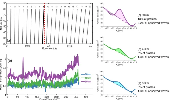
Figure 2. (a)Equivalent projection on the instrument primary mirror elevation angle of a feature of a wavelength indicated by numerical
values at the top of each line, as a function of altitude. Grey dashed line indicates approximate wavelength (in elevation angle space) of blockage-induced oscillations illustrated in Fig. 5 of Gille et al. (2008); bold line indicates nearest calculated wavelength to this angle. (b)Time series of the ratio between the observed number of waves at log10(kz)= −3.653 (peak of anomalous bump) and log10(kz)= −3.530 (trough between two peaks, where data approximate a linear fit to the distribution) for daily global-mean data at three height levels. Horizontal solid line indicates the ratio that would be observed if data were extrapolated linearly over the anomalous region.(c–e)Close-up illustration of the peak at log(kz)∼ −3.65 for three height levels, illustrating the difference between the feature at each height (solid line) and a linear fit across the region (dashed lines). Coloured shaded region indicates positive anomaly; grey shaded region indicates region of possible wave undersampling, discussed in the text.
fects. We see that, in general, the size of the feature co-varies at all three levels, with the amplitude of the feature increas-ing with height. Separate analyses (omitted for brevity) fur-ther show that the feature does not vary systematically as a function of latitude, height range of data supplied to the S-Transform analysis, or wavelet size used; thus, it is unlikely that the feature arises from the analysis methodology. Taken together, these two figures suggest a possible explanation in terms of the instrument blockage.
As shown in Fig. 5 of Gille et al. (2008), the uncorrected HIRDLS data from the instrument exhibit strong horizontal features in the measured radiance at a characteristic “wave-length” on the instrument focal plane corresponding to an el-evation scan angle∼0.09◦, assumed to be due to resonances in the Kapton blockage set up by contact with the mirror. As seen in Fig. 2a, this corresponds to an observed wavelength ∼9 km. The other observed peaks would then correspond to aliased near-multiples of this.
Validation exercises have previously suggested that this feature was successfully suppressed to below the level of the instrument noise by the correction and retrieval processing chain, but it is possible that some of this signal remains in the data. Since our gravity wave detection methodology (Sect. 3) examines the data for co-varying features in profiles, this will tend to select strongly for any such variation remaining after
processing, as the (uncorrected) blockage-induced signal will co-vary between profiles much more strongly than any true geophysical signal.
Figure 2c–e attempt to estimate the contribution to the ob-served spectrum arising due to this issue. Each panel shows, for the same three altitude levels as Fig. 2b, a zoomed-in re-gion of Fig. 1a, focusing on the anomalous peak centred at
kz>10−3.64cpm. In each case, we linearly interpolate across
transported by the “waves” they represent (see e.g. Figs. 5 and 8, discussed below).
Our results further suggest (Fig. 2c) that some real waves at close wavenumbers may be masked by these features. The purple shaded region shows our estimate of the positive anomaly (i.e. spurious additional waves) at this wavelength at 50 km altitude; the grey shaded region, meanwhile, shows an apparent deficit of observed waves at a slightly smaller wavenumber when compared to a linear fit. Since the de-tection method is based on the analysis of peaks in a spec-trum, it is thus likely that the spurious peaks in many profiles are “drowning out” the true spectral peaks at slightly smaller wavenumbers in profiles where such waves exist. This may particularly be the case at wavenumbers ∼10−3.85cpm. Here, we have comparatively few spectral points, and ob-serve a distinct “wiggling” of the obob-served spectrum: this is consistent with a spurious peak at 9 km wavelength affecting the true distribution around it to some degree.
Other methods of detecting gravity waves in HIRDLS data (e.g. Alexander et al., 2008; Ern and Preusse, 2012) have selected only for the one or at most two largest-amplitude signals in each profile, which may explain why this effect has not been noted previously. To test this, Fig. 1c illus-trates the results that would be obtained using the single-peak (HIRDLS-pk) method. We see no such anomalous sig-nal; this is partially due to the complete lack of signals at high kz, but the observed distribution includes the peak at
10−3.95cpm at which one of the peaks would be expected to occur, suggesting that in the majority of observed cases another, presumably geophysical, signal dominates over this effect. The features will also have been hidden in the previ-ous two studies using the current method, in Wright and Gille (2013) by the large bin size inkz at high wavenumbers and
in Wright et al. (2013) by the small momentum flux impact of this effect.
Since the majority of our following analysis focuses upon the observed wave spectrum decomposed as a function of bothkh andkz, it is difficult to remove these features. For
example, a simple downscaling of the number of observed waves in the regions centred on these peaks would be inac-curate, and hard to implement: in Fig. 5 (discussed below), we see that these peaks appear to spread across all horizontal wavenumbers rather than to be focused at a particular range, and thus any scaling-down of the number of observations at these vertical wavenumbers would be faced with the addi-tional task of identifying them in this second dimension. The time and height variation of the features (Fig. 2b) provides a further stumbling block to their removal. Finally, the tem-perature perturbation amplitudes of the signal are not eas-ily distinguished from the overall spectrum. Accordingly, we do not remove these data from our analyses, but instead in-clude them and address them directly where necessary. We do, however, attempt to mitigate the effect by only analysing data at vertical wavelengths shorter than 16 km; due to the spacing of output bins from the ST analysis, all bins at longer
vertical wavelengths will include at least one peak due to this effect, with no inter-peak gaps in the distribution allowing us to assess the relative contribution of the contaminating peaks. 5.2 Horizontal wavenumber
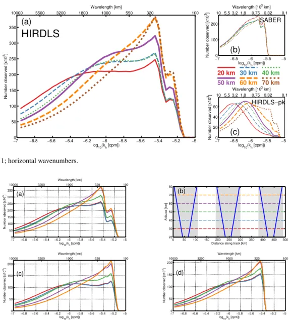
Figure 3 shows equivalent results for horizontal wavenum-berkh. We observe a distribution which rises as a function
of horizontal wavenumber. A flattening of the distribution is observed at intermediate wavenumbers,kh∼10−6.1–kh∼
10−5.6cpm; this appears to be due to the bias in observed
hor-izontal wavenumber at equatorial latitudes due to the merid-ional path of the satellite (Sect. 4.4), and is discussed further in Sect. 6. Aside from this flattening, the data otherwise rise consistently until a peak is reached atkh=10−5.35cpm.
Abovekh=10−5.35cpm, a discontinuity is observed, with
the absolute peak followed by a sudden drop and then by a secondary peak atkh=10−5.25cpm. This arises due to the
instrument scanning pattern (Sect. 4.3), and is explained by Fig. 4, discussed below.
A general trend is seen of the distribution shifting towards higherkhwith height; this will be discussed below.
Figure 3b and c show equivalent results for SABER and the HIRDLS-pk method. The HIRDLS-pk results show a dis-tribution falling off at horizontal wavenumbers greater than ∼10−6.7cpm at 20 km altitude, with the turning point in khincreasing with altitude; this suggests that the additional
waves contributed by the method of Wright and Gille (2013) may include significantly more short horizontal waves. Note, however, that it is difficult to ascertain the full effects of noise on our measurements. While the method is designed to mitigate against the inclusion of instrumental noise via the co-varying amplitude methodology and the noise-floor comparison, Ern et al. (2004) suggest that random fluctua-tions would peak at around 4×the horizontal sampling dis-tance, and increase with altitudes. Since we see these effects in all three data sets (HIRDLS, HIRDLS-pk and SABER), they may contribute to our distributions.
The SABER results, meanwhile, show a distribution with a form very similar to that of the primary HIRDLS results. This suggests that the anomalous blockage-induced peaks do not have a preferential apparent horizontal wavenumber, but are instead distributed across the whole observed wavenumber range.
High horizontal wavenumber discontinuity
Figure 4a shows the full observedkhdistribution,
(a)
HIRDLS
log10(kh [cpm])
Number observed [x10
3]
20 km 30 km 40 km
50 km 60 km 70 km
−70 −6.8 −6.6 −6.4 −6.2 −6 −5.8 −5.6 −5.4 −5.2 −5
50 100 150 200 250 300 350
10000 5500 3200 1800 1000 550 320 100
Wavelength [km]
−70 −6.5 −6 −5.5 −5
100 200
(b)
SABER
log10(kh [cpm])
Number observed [x10
3] 10 5.5 3.2 1.8 0.75 0.32 0.1
Wavelength [103 km]
(c)
HIRDLS−pk
log10(kh [cpm])
Number observed [x10
3]
−70 −6.5 −6 −5.5 −5
20 40 60
10 5.5 3.2 1.8 0.75 0.32 0.1
Wavelength [103 km]
Figure 3.As Fig. 1; horizontal wavenumbers.
Altitude [km]
Distance along track [km] (b)
0 50 100 150 200 250 300 350 400 450 500 20
30 40 50 60 70 80
log10(kh [cpm])
Number observed [x10
3]
(c)
−70 −6.8 −6.6 −6.4 −6.2 −6 −5.8 −5.6 −5.4 −5.2 −5 50
100 150 200
10000 3200 1000 320 100 Wavelength [km]
log10(kh [cpm])
Number observed [x10
3]
(d)
−7 −6.8 −6.6 −6.4 −6.2 −6 −5.8 −5.6 −5.4 −5.2 −5 0
50 100 150 200
10000 3200 1000 320 100 Wavelength [km]
log
10(kh [cpm])
Number observed [x10
3] (a)
−70 −6.8 −6.6 −6.4 −6.2 −6 −5.8 −5.6 −5.4 −5.2 −5 50
100 150 200 250 300 350
10000 3200 1000 320 100 Wavelength [km]
Figure 4. (a)Observedkh distribution for all observations, reproducing Fig. 3.(b)Illustration of instrument scanning pattern; blue lines
indicate sequential instrument scans, horizontal dashed lines indicate height levels shown in panels(a, c, d), and shaded (unshaded) regions indicated closely spaced (widely spaced) pairs.(c, d)Distributions for(c)closely spaced and(d)widely spaced profile pairs only.
of closely spaced (highlighted in grey) and widely spaced profile pairs. Since the measurablekhdepends strongly upon
the distance between profile pairs (Sect. 3), this imposes a different minimum observable wavelength for the closely spaced and widely spaced pairs.
To confirm this, Fig. 4c and d show, respectively, separate distributions for closely spaced profile pairs only and widely spaced profile pairs only. In both cases, we see a hard cutoff at the horizontal resolution limit, corresponding to the peak of each distribution. Since abovekh∼10−5.35 only closely
spaced profile pairs can contribute to our distribution, we see a sharp dropoff and secondary peak in the combined result.
To avoid this issue affecting our results, we omit widely spaced profile pairs from our analysis. This halves the num-ber of useful observations, but provides greater consistency
and a finer resolution limit without the need to correct for this effect.
6 Joint wavenumber analyses 6.1 Global mean
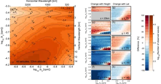
Figure 5a shows the distribution of observed waves as a func-tion of bothkh(horizontal axis) andkz(vertical axis), at the
Figure 5. (a)Global mean annual-mean distribution of the fraction of observed waves as a function of horizontal and vertical wavenumber at 32 km altitude.(b–f)differences from this distribution at five height levels, specified in the panel.(g–k)differences from this distribution for five latitude bands, centred on the latitude specified.
over a vast range of geophysical regimes, and accordingly is meaningful as a reference only.
We see that the observed numerical distribution is domi-nated by waves with small horizontal and vertical wavenum-bers, i.e. with long horizontal and vertical wavelengths, with the number of observed waves in bins in this region (bottom left to bottom centre) typically 2 or more orders of magni-tude above the numbers in the least-observed region at top left. This will at least partially relate to observational effects, rather than to the geophysical distribution of such waves; a wave with a longer wavelength in either direction is likely to have a larger physical extent, and is thus more likely to be observed in a measurement profile randomly located in the vicinity of the wave. Additionally, such waves are likely to induce larger temperature perturbations (Fig. 8b) and thus are more likely to be above instrument noise levels. Further-more, as shown by Fig. 4 of Preusse et al. (2002), the tem-perature perturbations of such waves will tend to be more easily detectable due to high instrument sensitivity. Duplica-tion effects are compounded in the horizontal direcDuplica-tion: as discussed above, it is highly non-trivial to distinguish be-tween the same horizontal feature in adjacent profiles, and consequently long horizontal waves may well appear in sev-eral profiles, particularly when the satellite is travelling in a similar direction to the wave vector. Future refinements of the analysis method will investigate this further, using methods based upon the Fourier uncertainty principle.
The smallest number of observed waves lies in the top left of the plot, i.e. large vertical wavenumber and small hori-zontal wavenumber. As discussed above, the paucity of ob-servations here in the vertical domain may well be due to random-sampling considerations; however, bias in observed horizontal waves would tend to increase rather than decrease the number of observed waves here, and detectability of their
temperature perturbations should be reasonable (although the amplitude of such waves may be low). As a result, the small number of waves observed in this region is likely to be a real effect, suggesting that the atmosphere may support compar-atively few short-vertical-long-horizontal-wavelength “pan-cake” waves.
We see the anomalous, presumably blockage-induced, spikes observed in Fig. 1 most strongly at top right; these do, however, extend across most of the horizontal range to at least some degree. Beneath these peaks, we continue to see a much higher number of waves than in the top left or bottom right, suggesting that even without the peaks this is a significant contributing region to the overall distribution. Finally, at bottom right, we see a region of few waves; this is consistent with the strongly reduced detectability at this combination of wavelengths. Detectability here should be by far the worst of any part of the 2-D spectrum; thus, the larger number of signals observed here than at, for example, the top left, may suggest that the atmosphere can support many short-horizontal-long-vertical-wavelength waves.
An apparent discrepancy is seen between our results and the HIRDLS-derived momentum flux wavenumber distribu-tions of Ern and Preusse (2012). There, a clear peak was seen in tropical waves atkh=10−5.75cpm andkz=10−3.90cpm.
to their analysis) atkh∼10−6.4cpm andkz≤10−4.2cpm in
our HIRDLS-pk distribution. The difference in kh peak
lo-cation arises due to the strong dependence of observed MF on wavenumber (Eq. 2). Part of the difference inkzpeak
lo-cation is explained by the slightly larger-kz waves observed
near the Equator (e.g. Fig. 5i and j) relative to other latitudes, but this cannot account for all of the differences, which may instead arise due to the very different analysis methods used. Subsequent panels of this figure (Fig. 5b–k) are shown as percentage differences from this 32 km global distribution, with colours representing the percentage difference in the proportion of total observed waves at a given (kh, kz). This
is a slightly complicated normalisation, but is chosen due to the small differences in visual appearance between un-differenced distributions; it should be noted that the distri-bution appears broadly identical at all heights when shown un-differenced2.
6.2 Height variations
Figures 5b–f show the difference between the observed dis-tribution at 32 km and that at five other height levels. Grey-shaded regions in individual panels indicate areas of the spec-tra which may experience edge truncation at that level.
We see two key trends, with increasing height leading to (i) larger horizontal and (ii) smaller vertical wavenumbers. The first such difference is clearly visible in Fig. 3 for all three data sets. The latter is harder to see in the absolute observed values seen in Fig. 1, and only becomes apparent when the data are normalised at each level individually; as discussed above, at least part of this change with height may be associated with noise effects. The change in vertical wave-length is consistent with previous observations dating back decades (e.g. Fritts, 1984, and references therein).
6.3 Latitudinal variations
Figures 5g–k show the differences from the global mean in Fig. 5a for the same analysis performed on specific 30◦ lati-tude bands centred on the latilati-tude indicated in the panel, all at the same 32 km altitude level. Note that the northerly limit to observations is at 80◦N, and thus that panel g only repre-sents the range 60–80◦N.
We see very clear differences, with a bias towards smaller horizontal wavenumbers near the Equator (between Fig. 5i and j) and towards larger horizontal wavenumbers at higher latitudes. As discussed in Sect. 4.4, this is at least par-tially due to the polar orbit of the instrument, which leads to the satellite travelling near-meridionally near the Equa-tor, combined with Coriolis parameter effects which allow a broader range of wave-intrinsic frequencies near the Equa-tor (Preusse et al., 2006). If we assume a zonal bias to the
2Compare e.g. Fig. 5g–k with Fig. 6α–ǫ, which show the same
data, with this normalisation in the former case and that used in Fig. 5a in the latter.
true wave field, observations here will tend to significantly over-measure the distance between phase fronts due to the geometry of the scan, and consequently significantly under-estimatekh. There is some difference in thekzdirection, with
smallerkzat higher latitudes and largerkznear the Equator,
but this effect is smaller than thekheffect; this is consistent
with e.g. Alexander et al. (2008), Yan et al. (2010) and Ern et al. (2011).
Aside from this, minimal differences are observed be-tween these distributions. This is largely due to thekheffect
drowning out such variation visually. To compensate for this, all following analyses will be normalised for latitude by com-paring only within a given latitude band or a given region.
7 Regional variations
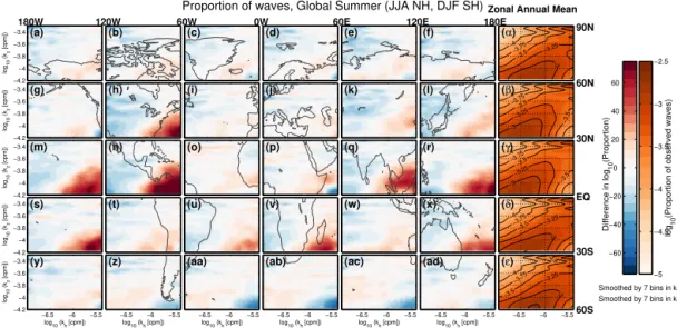
A large part of the remainder of this study will focus on re-gional variations in these above distributions. Figures 6–7 and 9–10 accordingly use a fixed set of regions, identical in each case. In each of these figures, each region (panels a–ad) is a 30◦latitude by 60◦longitude box, with boxes spanning from 60◦S to 90◦N and 180◦W to 180◦E. Note that data are not available poleward of 80◦N. Maps are plotted over these regions to aid interpretation; however, variations within each panel do not correspond to this subregional geography, but only to the distribution in the panel as a whole. Panelsα–ǫ, the rightmost column, will show zonal means for the corre-sponding latitude band.
Seasonal joint-wavenumber analyses
Figures 6 and 7 show the observed kh–kz distributions for
each of our geographic regions for global summer (JJA NH (Northern Hemisphere), DJF SH (Southern Hemisphere)) and winter (DJF NH, JJA SH) respectively. The panels are normalised in a similar way to Fig. 5b–k above, but with the differences being not from the annual mean global mean, but from the annual mean zonal mean at that latitude (shown identically in Figs. 6α–ǫ and 7α–ǫ). This allows us to fo-cus on variations other than the instrument- and Coriolis-parameter-induced variation in horizontal wavelength with latitude seen in Fig. 5g–k, which would otherwise dominate all panels. Analyses were also carried out for spring and au-tumn, but have been omitted for brevity as the variations they showed were much smaller than for summer and winter.
We see the largest relative variations at low latitudes and in the bottom right of each panel, i.e. lowkzand highkh. Since
−4 −3.75 −3.5 −3.25 −3 (α)
−6.5 −6 −5.5
−4 −3.75 −3.5 −3.5 −3.25 −3 (β)
−6.5 −6 −5.5
−4 −3.75 −3.5 −3.5 −3.25 −3 (γ)
−6.5 −6 −5.5
−4 −3.75 −3.5 −3.25 −3 (δ)
−6.5 −6 −5.5
−4 −3.75 −3.5 −3.5 −3.25 −3 (ε)
−6.5 −6 −5.5
log 10 (k z [cpm]) (a) −4.2 −4 −3.8 −3.6
−3.4 (b) (c) (d) (e) (f)
log 10 (k z [cpm]) (g) −4.2 −4 −3.8 −3.6
−3.4 (h) (i) (j) (k) (l)
log 10 (k z [cpm]) (m) −4.2 −4 −3.8 −3.6
−3.4 (n) (o) (p) (q) (r)
log 10 (k z [cpm]) (s) −4.2 −4 −3.8 −3.6
−3.4 (t) (u) (v) (w) (x)
log
10 (kh [cpm])
log 10 (k z [cpm]) (y)
−6.5 −6 −5.5 −4.2 −4 −3.8 −3.6 −3.4 log
10 (kh [cpm]) (z)
−6.5 −6 −5.5 log
10 (kh [cpm]) (aa)
−6.5 −6 −5.5 log
10 (kh [cpm]) (ab)
−6.5 −6 −5.5 log
10 (kh [cpm]) (ac)
−6.5 −6 −5.5 log
10 (kh [cpm]) (ad)
−6.5 −6 −5.5
−5 −4.5 −4 −3.5 −3 −2.5 −60 −40 −20 0 20 40 60
Proportion of waves, Global Summer (JJA NH, DJF SH)
60S 30S EQ 30N 60N 90N 180E 120E 60E 0W 60W 120W 180W
Zonal Annual Mean
Difference in log
10
(Proportion)
log
10
(Proportion of observed waves)
Smoothed by 7 bins in kh Smoothed by 7 bins in kz
Figure 6.(α–ǫ)Zonal mean annual-mean distributions of the fraction of total observed waves for each latitude, as a function ofkhandkz.(a–
ad)Equivalent distributions for each of our analysis regions in summer (JJA in the Northern Hemisphere, DJF in the Southern Hemisphere). Data are shown as differences from the corresponding zonal mean annual mean. A global map is overplotted for easy identification of geographic regions; note that the data shown in each panel are as a function ofkz andkh only, and are not related in any way to the geography at scales below that of the region box. All values at 32 km.
−4
−3.5
−3 (α)
−6.5 −6 −5.5
−4
−3.5
−3.25
−3 (β)
−6.5 −6 −5.5
−4 −3.5
−3.25
−3 (γ)
−6.5 −6 −5.5
−4
−3.75 −3.5
−3 (δ)
−6.5 −6 −5.5
−4 −3.75
−3.5
−3 (ε)
−6.5 −6 −5.5
log 10 (k z [cpm]) (a) −4.2 −4 −3.8 −3.6
−3.4 (b) (c) (d) (e) (f)
log 10 (k z [cpm]) (g) −4.2 −4 −3.8 −3.6
−3.4 (h) (i) (j) (k) (l)
log 10 (k z [cpm]) (m) −4.2 −4 −3.8 −3.6
−3.4 (n) (o) (p) (q) (r)
log 10 (k z [cpm]) (s) −4.2 −4 −3.8 −3.6
−3.4 (t) (u) (v) (w) (x)
log10 (kh [cpm])
log 10 (k z [cpm]) (y)
−6.5 −6 −5.5
−4.2 −4 −3.8 −3.6 −3.4
log10 (kh [cpm])
(z)
−6.5 −6 −5.5
log10 (kh [cpm])
(aa)
−6.5 −6 −5.5
log10 (kh [cpm])
(ab)
−6.5 −6 −5.5
log10 (kh [cpm])
(ac)
−6.5 −6 −5.5
log10 (kh [cpm])
(ad)
−6.5 −6 −5.5
−5 −4.5 −4 −3.5 −3 −2.5 −60 −40 −20 0 20 40 60 Proportion of waves, Global Winter (DJF NH, JJA SH)
60S 30S EQ 30N 60N 90N 180E 120E 60E 0W 60W 120W 180W
Zonal Annual Mean
Difference in log
10
(Proportion)
log
10
(Proportion of observed waves)
Smoothed by 7 bins in kh
Smoothed by 7 bins in kz
Figure 7.As Fig. 6 for global winter (DJF in the Northern Hemisphere, JJA in the Southern Hemisphere).
change of the QBO winds over the 6 months between Figs. 6 and 7. Examination of a longer period of time would help to elucidate this, but even the full 3 years of HIRDLS data are unlikely to provide a sufficiently long record to decou-ple this effect comdecou-pletely. Source changes are likely to be the dominant of the two factors due to the strong seasonality of convective activity in this region (e.g. Wright and Gille, 2011).
Smaller differences are seen at higher latitudes, and do not display such strong seasonal variation. In particular, at the highest latitudes, we often see an enhancement relative to the annual mean at many wavelengths in both summer and win-ter, i.e. large numbers in these seasons and low numbers in
autumn and spring (not shown). Due to this behaviour, these regions are discussed below, where whole-year time series are shown.
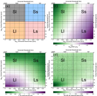
8 Relative variations of wave sub-species 8.1 Definitions and relative importance
evolution of these individual components of the distribution. Figure 8a accordingly divides the overall observed wave dis-tribution into four distinct subtypes, or species, defined by wavenumber: short-vertical long-horizontal (“Sl”, top left), short-vertical short-horizontal (“Ss”, top right), long-vertical long-horizontal (“Ll”, bottom left), and long-vertical short-horizontal (“Ls”, bottom right).
Figure 8b shows the mean temperature anomaly associated with eachkh–kzcombination, indicating that the largest
tem-perature perturbations are associated with species Ll. From this, one might initially conclude that waves of species Ll were the most important, due to their large amplitude – in particular, this implies a large potential energy per wave,
(1/2)(g/N )2(T /T )ˆ 2. However, a vitally important
geophys-ical quantity is the MF transported by the waves – in par-ticular, this is one of the key parameters used in weather and climate modelling. In the mid-frequency approximation, this can be characterised by Eq. (2) above. There are three key variable terms in this which we can derive directly from HIRDLS data:kh,kzandT /Tˆ , wherekzandkh combine in
the ratiokh/kz. For the waves we can observe with HIRDLS,
this ratio can vary over nearly 3 orders of magnitude, as shown in Fig. 8c. As a consequence of this, the observed momentum flux per wave, Fig. 8d, is almost entirely dom-inated by Ls waves, particularly those at the very largestkh
and smallestkz, which as shown by Figs. 6 and 7 represent
the bulk of the variability in our observations oncek–h varia-tions due to orbital geometry and/or the variation of the Cori-olis parameter with latitude are removed. Our results suggest, therefore, that variations in the number of observed Ls waves appear critically important to the variability of the global MF distribution in a much more fundamental way than the other three species.
As shown by Fig. 5, the global numerical distribution of observed waves is dominated by waves of species Ll and Ss. This numerical dominance of species Ll may be due in part to their larger mean temperature perturbations (Fig. 8b) and consequent easier detection in temperature data; how-ever, this clearly cannot be the whole reason, due to the rela-tively small mean temperature perturbations for species Ss. 8.2 Absolute and relative variations of observed species Figure 9 examines the time variation over the year 2007 for each of our four wave species, as a time series of the total number of observed waves per profile. The data exhibit sig-nificant day-to-day variability, and have been smoothed by 2 weeks to aid interpretation.
In general, the most-observed species is type Ss, with around 1.0–1.3 waves per profile (wpp) in most regions and at most times, whilst the least-observed species is type Sl, with typically∼0.4 wpp. The former type includes a signif-icant contribution from the anomalous subpeaks, which may contribute to the large number of observed signals, while the latter is difficult to detect due to limb-sounding sensitivity
Figure 8. (a)Diagram indicating the four species of waves we
de-fine and examine. In terms of wavelength, these are short-vertical, short-horizontal (Ss, top right), short-vertical long-horizontal (Sl, top left), vertical short-horizontal (Ls, bottom right), and long-vertical long-horizontal (Ll, bottom left). (b) Observed annual-mean global-annual-mean temperature perturbations per wave event,(c) ra-tiokh/kz, and(d)observed annual-mean global-mean momentum flux per wave event for analysed wavelength combinations. All val-ues at 32 km.
considerations (Preusse et al., 2002), which may explain the comparatively low number. However, this limitation applies more strongly to waves of type Ls, and thus cannot fully ex-plain the difference. The number of observed waves of the two long-vertical species, Ls and Ll, in general lie between these values, with both Ls and Ll varying between around 0.4 and 1.4 wpp over the course of the year.
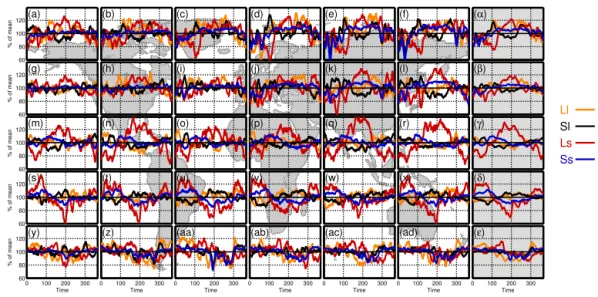
Figure 10, meanwhile, shows the same data, normalised such that the annual mean value for each species equals 100. This emphasises the variability of each species with re-spect to time, and shows that, while in some regions and at some times all four species can vary together, at others dif-ferent species can vary independently of each other, often with some apparent compensation between different species as one rises in observed frequency to take the place of an-other. The latter effect will be discussed further in Sect. 8.3.
Deviations from the mean are observed at Arctic latitudes in winter and spring, specifically between days 1 and 100 in Fig. 10c–f. The relatively low numbers during this time are consistent with filtering of waves by the polar vortex, and the variations coincide with vortex influences by large-scale planetary waves.
0 0.5 1 1.5
(a)
wpp
(b) (c) (d) (e) (f) (α)
0 0.5 1 1.5
(g)
wpp
(h) (i) (j) (k) (l) (β)
0 0.5 1 1.5
(m)
wpp
(n) (o) (p) (q) (r) (γ)
0 0.5 1 1.5
(s)
wpp
(t) (u) (v) (w) (x) (δ)
0 100 200 300 0
0.5 1 1.5
(y)
Time
wpp
0 100 200 300
(z)
Time
0 100 200 300
(aa)
Time
0 100 200 300
(ab)
Time
0 100 200 300
(ac)
Time
0 100 200 300
(ad)
Time
0 100 200 300
(ε)
Time
Ll
Sl Ls
Ss
Figure 9. (a–ad)Regional time series showing the number of observed waves per profile (wpp) for each species. Note that wpp are defined
as waves present at the analysis level, which does not necessarily correspond to the profile as a whole. Data have been smoothed by 2 weeks.
(α–ǫ)Zonal mean time series. Units of time are calendar day from 1 January. All values at 32 km.
60 80 100 120(a)
% of mean
(b) (c) (d) (e) (f) (α)
60 80 100 120(g)
% of mean
(h) (i) (j) (k) (l) (β)
60 80 100 120(m)
% of mean
(n) (o) (p) (q) (r) (γ)
60 80 100 120(s)
% of mean
(t) (u) (v) (w) (x) (δ)
0 100 200 300
60 80 100 120(y)
Time
% of mean
0 100 200 300
(z)
Time
0 100 200 300
(aa)
Time
0 100 200 300
(ab)
Time
0 100 200 300
(ac)
Time
0 100 200 300
(ad)
Time
0 100 200 300
(ε)
Time
Ll Sl
Ls
Ss
Figure 10.As Fig. 9 but normalised such that the annual mean for each species is equal to 100.
γ–δ. This has important consequences: as discussed above, this species is by far the dominant carrier of large momen-tum fluxes, and the large temporal variations of these species thus contribute significantly to the temporal variability of MF. In particular, we see large peaks in the observed number of Ls waves during monsoon periods in monsoon regions, i.e. Fig. 10n, p, q, r, γ in NH summer and Fig. 10t, u, v, x, δ in SH summer (Li and Zeng, 2002; Wright and Gille, 2011). This suggests that the large momentum fluxes previ-ously observed to be associated with the monsoon (Wright and Gille, 2011) are dominantly carried by Ls waves; the correlation between our Ls wave time series and outgoing longwave radiation (OLR) over the particularly intense mon-soon regions (panels q and r), for example, is∼ −0.7. This is consistent with previous work, e.g. Jiang et al. (2004) and
Ern and Preusse (2012). The absolute number of observed Ls waves is not especially low compared to other regions at the same latitude during the other parts of the year (e.g. Fig. 9m, o in NH summer), suggesting that the relatively low value during the other parts of the year are a baseline rather than a reduction in Ls waves due to other processes.
con-tinues downstream of the hotspot through Fig. 10ab–ad and round to Fig. 10y, leading to a very strong such reduction in the zonal mean (Fig. 10ǫ). Figure 9 emphasises that this is an actual reduction rather than a normalisation artifact. This suggests that the increase in MF observed during this period is not due to increased dominance of any one species, but instead due to a significant increase in MF per wave carried by all four types, dominating over a reduced absolute num-ber of waves. A possible alternative explanation could be that large-amplitude peaks in theT′(kz)distribution “drown out”
smaller peaks which would be visible in other seasons, lead-ing to an apparent reduction in the total number observed; however, the drop appears to apply to all four species, and this effect would therefore have to be extremely large to ex-plain the overall reduction.
8.3 Differences between generated and observed species
It would be tempting to conclude that the variation of the species we observe is due primarily to source mechanisms operating at tropospheric and near-surface altitudes. How-ever, while this may be the case in many places and times, we cannot generally assume this.
A particular example of a process which will lead to a wave being generated with one species but being observed as another is illustrated in Fig. 11, adapted from Nappo (2002). Here, we illustrate how critical-layer wind filtering and the consequent refraction of waves just below such a critical layer of gravity waves would lead to a wave observed at a low altitude with type L (i.e. long-vertical-wavelength) would be observed at a height nearer a critical level with type S (i.e. short-vertical-wavelength).
The wave initially propagates along a given group veloc-ity vectorvg1, with wavefronts as indicated on the diagram.
An observation taken here, indicated by the dashed oval, will measure a relatively long vertical wavelength due to the large difference in geometric height between the wavefronts, with some compression of the vertical wavefronts due to the ap-proaching critical level.
At some later time, the wave has propagated some distance and approaches a critical layer zc. As the wave approaches
this layer, the vertical component of the group velocityvg2
tends towards zero, causing the wavefronts to realign. Were the observation (dashed oval) to be taken here instead of at the first location, a much shorter vertical wavelength would be measured.
As a result, the HIRDLS observation will show it to in-stead be of type S in the second instance and type L in the first, despite having the same source. Furthermore, an obser-vation slightly higher in altitude will not observe the wave at all, consequently reducing the number of observed waves. Analogous processes could also operate in the horizontal direction (not illustrated), or could operate to take a wave packet completely out of our observational filter, causing it
z=z c z
x vg1
k1
vg2
k2
Figure 11.Diagram illustrating an example of a process whereby
wind shear would cause the same wave to be observed at two differ-ent vertical wavelengths. Adapted from Nappo (2002). See text for details.
to disappear from the results despite remaining present in the physical atmosphere.
Such processes could serve to explain at least some cases where we see a reduction of waves in one type and a compen-sating increase in waves of another type; in such situations, it may be the case that the generation mechanism has remained constant throughout, but wind layers have altered the wave properties before the point of observation. Many other simi-lar and dissimisimi-lar mechanisms may operate, and may operate multiple times on the same wave as it travels through the at-mosphere; we only include one example to illustrate this like-lihood. While our observed variations in the relative number of each wave may be indicative of source terms, there are many confounding geophysical mechanisms even assuming a perfect instrument.
9 Discussion and conclusions
In this study, we have presented an analysis of a full year of HIRDLS data using an overlapping gravity wave detection methodology, including a detailed description of the associ-ated caveats, and explained why our results and methodology differ from previous studies by allowing for the detection of multiple overlapping wavelike signals in a profile. We fur-ther identify a series of anomalous features in the observed data, and demonstrate that these most probably arise from the known effects of the HIRDLS launch anomaly, that the sig-nals produced by this anomaly rarely if ever dominate over the largest geophysical signals, and that they contribute at most 10–12 % of the observed signals, all of low amplitude.
We then considered the distribution of the number of ob-served waves as a function of bothkh andkz, in the global