Tribology in Industry
www.tribology.fink.rs
Traction Possibilities of Mining Railways with
Frictional Drives
F. Kazimierz
aa AGH University of Science and Technology, Cracow, Poland
A B S T R A C T Keywords:
Friction Traction Mining railways
Corresponding author:
F. Kazimierz
AGH University of Science and Technology, Cracow, Poland E-mail:fukaz@agh.edu.pl
Present market conditions prefer an implementation in mining some highly efficient coal longwalls, which must be insured with a supply of proper machines and equipment as well as working there men, mainly by suspended and floor(narrow-gauge) railways. A frictional contact of engine driving wheels with rails of these railways limits their traction possibilities in the essential way, particularly onto rails of increased slopes.
In the paper an analysis of traction possibilities of mining railways with frictional drives from the point of view of their operating on rail inclination, taking on consideration the different ways of thrust of driving wheels onto rail has been carried out. They were also given the dependences for the calculation of required frictional contact forces of wheels on rails and boundary track inclinations, which can be overcame by the railways with frictional drives.
© 2012 Published by Faculty of Engineering
1. INTRODUCTION
At present in coal mining there are such market conditions, which prefer the highly efficient longwall systems, which must be provide with supply of convenient machines and equipment as well as mining men , mainly due to suspended and floor running railways of frictional drives. An essential influence on traction possibilities and safety exploitation of these railways has the frictional contact (adhesion forces) of driving wheels with rails, particularly onto rails of increased slopes [1,2,3].
The scope of the paper covers an analysis of traction possibilities of railways with frictional contact taking onto consideration the different ways of thrust operation for driving wheels on rails as well as conditions of their adhesion. The
purpose of this analysis presents the given dependences for calculation of required frictional contact forces of engine driving wheels with rails and track inclination, which can be overcoming during the realization of haulage duties. One was also shown the technology ways which could increase the traction possibilities of railways with frictional drives, useful in their exploitation [5].
2. CONSTRUCTION SOLUTIONS OF UNDERGROUND RAILWAYS WITH FRICTIONAL DRIVES
According to the mining and geological conditions as well as kind of hauling loads two types of railways are used in underground
R
E
S
E
A
R
C
mining: the suspended and floor (narrow-gauge) railways [Fig. 1].
Fig. 1. View of railways with frictional drives: a) suspended railway; b) floor railway.
A haulage of more weight loads onto tracks of greater inclinations demands the big traction forces. For their production in construction solutions of these railways an equivalent driving wheel thrust on rails could be produced applying the following:
1. engine (tractor) weight or
2. operational system of constant thrust of
driving wheels on rails (e.g. hydraulic, spring ones) or also
3. automatic control system of thrust of driving wheels on rails depending on movement resistances of railway [1].
In the first case one of essential constraints in the implementation of conventional railways (adhesion ones) is a possibility of going only on negligible track inclinations (to about 2,5°), because with its increase the railway resistances rise and the thrust of driving wheels of engine on rails decreases, thus it also decreases the force of adhesion. The next two cases allow extending a range of gone inclinations but with the increase of track inclination the railway movement resistances rise as well as value of demanded
thrust of driving wheels. In consequences these drives on greater inclinations are becoming less effective, because of limited permissible single thrusts into wheel and rail contact.
Below the traction possibilities of railways for the above mentioned ways of accomplish of driving wheel thrust on rails according to α angle track inclination and conditions of their frictional contact, i.e. from the adhesion coefficient value Ψ have been analyzed.
3. ANALYSIS OF RAILWAY TRACTION POSSIBILITIES IN A CASE OF DRIVING WHEEL THRUST ON RAILS CAUSED BY THE ENGINE WEIGHT
In conventional railways as a hauling force the adhesion force of driving wheels toward rails produced by its weight has been utilized. On inclined track this force amounts:
F =ψ ⋅G⋅cosα. (1)
It results from the above dependence those in conventional railways at given value of G engine weight the force of adhesion depends on an angle of track inclination and adhesion coefficient. This coefficient depends on many factors, among others on kind of materials of the wheel-rail pair, conditions of their frictional cooperation (environment temperature, kind and stage of rail pollution, loading, velocity), and also on slip of driving wheel against a rail [1]. The adhesion coefficient dependence of wheel toward a rail from its relative slid (Fig. 2) has two different qualitative ranges:
1. elastic slid, where there is a good adhesion of wheel to rail (v≤νgr),
2. combined slip, where driving wheel can transfer into undesirable macroslip (v> νgr).
υ ψ
υgr
Fig. 2. Diagram of Ψ adhesion coefficient dependence from the u wheel slid relative velocity.
a)
Frictional drives ought to be design in such a way, that the upper part of adhesion curve should correspond to the frictional cooperation of wheel with a rail in the range of elastic slip.
o W dt dv g
Q k G k w
Q G
W=( + )⋅( ⋅cosα+sinα)+ '⋅ + "⋅ ⋅ + (2)
where k’, k’’ – of mass reduction coefficient of revolving parts into the engine and hauling draft of cars; t – time; Wo – additional resistances (i.e.
on arches).
The maximum track inclination, which can be overcame by the engine with draft of cars of Q weight one be obtained in stabile movement, so at v = const and Wo = 0. In such a case F = W
and from dependences (1) and (2) after transformations one obtains an equation:
α ψ
tg w n G
Q G
+ = = +
. (3)
from which a required weight of G engine amounts:
ψ α)
(w tg
Q
G= ⋅ + . (4)
and a single weight, so relative to the rail:
ψ α
tg w Q G
G
njg = +
+
= . (5)
From the dependence (3) one can calculate a α boundary angle of track inclination, which can be run by the railway amounts:
( w)
n arctg −
= ψ
α . (6)
Using dependence (6) the curves for assumed data have been done and presented in Fig.3.
0.1 0.2 0.3 0.4 0.5
0 5 10 15 20 25
α1( )ψ
α2( )ψ
α3( )ψ
ψ
n = 1
n = 2
[o] n = 3
Fig. 3. Curves of dependences α = α(ψ); α1at n = 1 (Q = 0); α2at n = 2; α3at n = 3; w = 0,05.
From the dependence (6) for assumed values ψ, n and w one can calculate the value of track
inclination angle, which the engine alone or with the draft of cars can still overcome.
In Fig. 4 there are diagrams given as the examples n(α) – w = 0,05 and ψ = 0,1; 0,2; 0,3; 0,4; 0,5 – from these one can denote the n parameter values at given α angle of track inclination. It is easy to find out that with the increase of value of α angle of track inclination. The railway traction possibilities expressed by the value of n parameter are fast diminishing and in the range of small inclinations α in essential way depend on coefficient values: ψ adhesion and w movement resistances values. Substituting into the (6) dependence n = 1 one can calculate the boundary values of track inclination angle, which can only overcame the engine alone (e.g. at Q = 0) i.e. at ψ=0,2 and w = 0,05 the boundary angle of inclination amounts α=8,53°.
0 5 10 15 20 25 30
0 2 4 6 8 10
n1( )α
n2( )α
n3( )α
n4( )α
n5( )α
1
α
Fig. 4. Diagrams of dependence n = n(α) for conventional railway (n1 at ψ= 0,1,n2 at ψ = 0,3, n4 at ψ= 0,4, n5 at ψ = 0,5, w = 0,05).
Figure 4 shows, that in such construction solution of friction drive a prevailing influence on railway hauling possibilities has the value of
ψ adhesion coefficient and α track inclination angle, but the range of possible inclinations to overcome by the railway is possibly little.
4. ANALYSIS OF RAILWAY TRACTION POSSIBILITIES IN A CASE OF CONSTANT THRUST OF DRIVING WHEELS ON RAILS
In a case of constant thrust of driving wheels on rails, at the Ns constant assign thrust of driving
wheels on rails (which can be controlled) Their constant adhesion force amounts:
F =ψ ⋅Ns. (7)
resistances expressed by the dependence (2), at v = const and Wo as well as additional
resistances caused with the Ns thrust force of
driving wheels on railsone obtains :
α α ψ sin cos ' + − = = + w w s N Q G s
. (8)
hence required Ns driving wheel thrust on rails
amounts: ' ) sin cos ( ) ( w w Q G
Ns −
+ ⋅
+ =
ψ α α . (9)
and a single thrust, e.g. relative to the railway weight : ' sin cos w w Q G N
njs s −
+ =
+ =
ψα α . (10)
In this case Ns thrust of driving wheels on rails
must be selected in such a way, that will ensure the correct frictional cooperation of driving wheels with a track in conditions of their less adhesion during the most weight hauling load on the most inclined track section.
From the dependence (8) the value of boundary angle of track inclination, which can still be overcame by the railway (Fig. 5) amounts:
+ − − + − + −
= ( ') 1]
) 1 ( ) 1 ( ' arcsin )
( 2 2
2 2 s w w w w w s w ψ ψ ψ
α (11)
0.1 0.2 0.3 0.4 0.5
0 5 10 15 20 25 30
α1(ψ)
α2(ψ)
α3(ψ)
α4(ψ)
α5(ψ)
ψ
[o] [o]
Fig. 5. Diagrams of dependence α = α(ψ) at α1 at s1= 1,2; α2 at s2 =2; α3 at s3 = 3; α4 at s4 = 4; α5 at s5 = 5; w = 0,05, α = α(ψ), w’= 0,005.
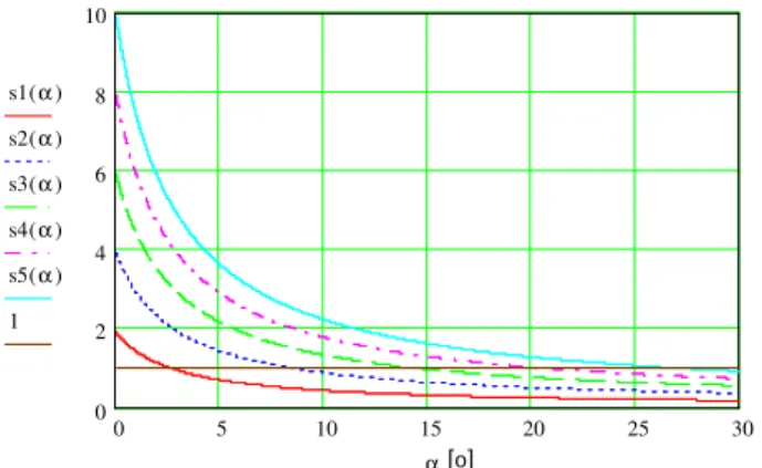
For assumed data the diagrams of dependence s = s(α) are presented in Fig. 6.
A quotient of n and s values expressed by dependences (3) and (8) amounts:
α α α α cos sin cos = + + = = tg w w s n r
and was presented in Fig. 7 as the α angle function.
0 5 10 15 20 25 30
0 2 4 6 8 10
s1( )α
s2( )α
s3( )α
s4( )α
s5( )α
1
α[o]
Fig. 6. Diagrams of dependence s = s(α) for railway of constant driving wheel thrust on rails (s1 at ψ = 0,1;
s2 at ψ = 0,2; s3 at ψ= 0,3; s4 at ψ = 0,4; s5 at ψ = 0,5;
w = 0,05, w’= 0,005).
5 10 15 20 25 30
0.8 0.85 0.9 0.95 1
r( )α
α [o]
Fig. 7. Diagram of r = r(α) dependence.
From Fig. 7 one can see that in the range of
α = 0 ÷ 30° angle value, the s parameter value is greater than n of 0 ÷ 15,5 %, what shows for greater of the same grade possibilities of overcoming of inclinations by the railway with a constant thrust of driving wheels on rails, comparing with this one, in which the thrust is accomplished by the engine weight.
5. ANALYSIS OF TRACTION POSSIBILITIES OF RAILWAYS IN A CASE OF AUTOMATION CONTROL OF DRIVING WHEEL THRUST ON RAILS
wheels in the less profitable conditions do not go into a macroslip. Due to this an enlargement of track inclination range, which can be overcame by the railway of such a drive, is possible. The F adhesion force of driving wheels pressed against a rail with the P force is expressed by dependence:
F =ψ⋅P
(12)
and at Ψ = const will change in proportional way as the P force change. Thus one ought to do the P automation control thrust force according to the required adhesion force. The F force is still difficult to use as a signal to wheel thrust control on rails, because its part is applied for the overcoming of resistances occurring into a driving wheel and rail contact zone.
So as a signal it is due to use a hauling force which can be treated as directly proportional to adhesion force and equal to the W railway movement resistances (without driving wheel movement resistances).
Assuming the W railway movement resistances as an initial quantity the process control of driving wheel thrust on rails ought to fulfill the following dependences [1]:
P=m⋅W (13)
where m – is a coefficient (ratio) of feedback track in automatic control system of driving wheel thrust on rails.
Simultaneously there is fulfilled an equation:
P w W
F= + ' (14)
where w’ is a coefficient (dimensionless) characterizing the resistances into the driving wheel and rail contact zone.
The equations (12), (13) and (14) describe a process of operation of hauling force by the system of elastic slid of driving wheels and define interdependence between the F, P and W forces. The decrease of the P force to 0 denotes a loss of contact of driving wheel contact with rails, what is inadmissible, so the equation (13) must have a shape:
P=m⋅W ≥m⋅N (15)
where N = (0,02), 0,05) Wmax is a given “initial
tension” in the system for a providing the driving wheels into a contact with rails, with the
W resistances equal or near to 0 (i.e. at the moment of starting, at passing from a starting to a braking).
From the dependences (13), (14) and (15) one obtains:
' 1
w m
− =
ψ (16)
It is shown from the dependence (13), that at the given maximum thrust of driving wheels on rails P = Pmax (permissible i.e. from resistance conditions of the wheel-rail pair) a usable hauling force equal to rail movement resistances amounts: W = Pmax/m.
If a mechanical efficiency of track feedback be near 1,0 the coefficient m one can observe as a hauling mechanism geometric ratio and its biggest force one can obtain, when the m coefficient takes possibly the less values, with which a correct adhesion of driving wheels to rails be continued in the less profitable conditions of their frictional cooperation. The such defined ratio m = mo insures a full
usefulness of adhesion force (thus W = Wmax) at
the P given maximum thrust of driving wheels on rails and such a solution of hauling mechanism we can accept as the optimum one. At the m > mo with an increase W there is the proportional increase of wheel thrust on rails and achieves Pmax at W < Wmax; when m < mo next the wheel slid will occur. These were presented in Fig. 8 [1].
Fig. 8. Ranges of frictional cooperation of wheel with rail according to the m parameter [1].
It results from the above consideration, that the m parameter is the basic value in a design of optimal frictional drives with the automatic control thrust of driving wheel thrust on rails. For the assignment of its values it is necessary a reliable knowledge of coefficient values ψ and w’ corresponding with cooperating frictional conditions of wheel with rail. A state of rail surface (pollution) has a deciding influence. On the basis of experimental
2 1 0
W2= Pmax/m W1=Pmax/m Wmax= (ψ-w’)Pmax Pmax
investigations carried out at the University of Science and Technology AGH in Cracow, Poland for the pair: wheel- rail ( cast steel – steel) one has obtained mo = 3,84 for dry rails, fine technologically and mo = 24,25 for wet rails, polluted by coal and stone dust.
One ought to take on consideration the fact, that in such a solution of railway drive construction, with a properly selected track ratio of feedback, theoretically there are not any limits of track inclination, which the railway has to overcome, but in practice it is limited by the Pmax force value, relatively great for a given track inclination. The maximum track inclination which could still overcome would be obtained at the fixed velocity of railway movement v = const and Wo= 0. From the construction point of view for the assumed P = Pmax value of driving wheel thrust on rails this inclination could be assigned applying the dependences (12), (15) and (16) from the equation:
α α ψ sin cos ' + ⋅ − = = + w w k P Q G
(17)
and a required P thrust of driving wheels on rails should amount:
' ) sin cos ( ) ( w w Q G k Q G P − + ⋅ + = + =
ψ α α (18)
The thrust related to the railway weight unit will amount: ' sin cos w w Q G P
njk −
+ = + = ψ α α (19)
and will has the same shape as in the case of constant thrust of driving wheels [dependence (10)].
Hence the maximum track inclination angle value, which could be overcome by the railway, according to the dependence (11) should have the shape: + − − + − + −
= ( ') 1]
) 1 ( ) 1 ( ' arcsin )
( 2 2
2 2 k w w w w w k w ψ ψ ψ
α (20)
thus in this case we should obtain the diagrams presented in Fig. 9, just the same as in Fig. 6.
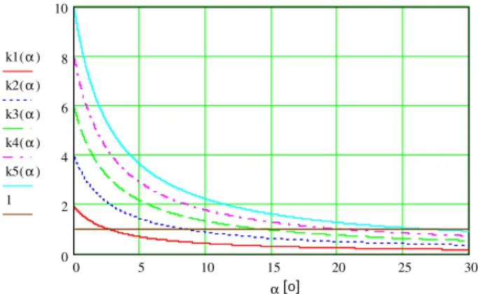
An ordinate k = 0,1 in crossing with relevant curves k(α) assign these values of α boundary angle where the thrust of driving wheels on rails is equal to the rail weight.
0 5 10 15 20 25 30
0 2 4 6 8 10
k1( )α
k2( )α
k3( )α
k4( )α
k5( )α
1
α[o]
Fig. 9. Diagrams of k = k(α) dependence for the railway with automatic control of driving wheel thrust on rails (k1 at ψ = 0,1; k2 at ψ = 0,2; k3 at ψ = 0,3; k4 at ψ = 0,4; k5 at ψ = 0,5; w = 0,05; w’ = 0,005).
As one can see from Fig. 9, at the given thrust of driving wheels on rails the adhesion coefficient value decides of track inclination values, possible to overcome by the railway. It is also shown in Fig. 9 that with the increase of α angle of track inclination required thrust of driving wheels on rail P = (Gl + Q)/k strongly increases
and in practice this is an essential limitation. However the giving great P thrust forces is connected with necessity of application of wheels of great dimensions (for do not extend admissible stresses into wheel with rail contact) or their important amount and highly resistant materials, what is rather complicated and raises the costs of construction of these drives. The diagrams of dependence of njk(α) unitary thrust for this way of driving wheel thrust producing on rail, with different adhesion coefficient values, were presented in Fig. 10.
0 5 10 15 20 25 30
0 1 2 3 4 5 6
njk1( )α
njk5( )α
α[o]
Fig. 10. Diagrams of njk = njk(α) dependence for the railway with thrust automatic control of driving wheels on rails (njk1 at ψ = 0,1; njk5 at
ψ
=0,5;w = 0,05 and w’ = 0,005).
rails with the weight equal to the weight of rail (k1=1), the value of boundary angle of track
inclination changes according to the curve
α1(ψ), and during the thrust equal of a half of rail weight (k2 = 2) according a curve α2(ψ) and so on. This diagram confirms that for the overcoming substantial inclinations at rather not great thrusts of driving wheels on rails, it is due to assure possibly great adhesion coefficient values of the pair of driving wheel – rail.
0.1 0.2 0.3 0.4 0.5
0 5 10 15 20 25 30
α1(ψ)
α2(ψ)
α3(ψ)
α4(ψ)
α5(ψ)
ψ
[o] [o] [o]
Fig. 11. Diagrams of α = α(ψ) dependence for a railway with automatic control of driving wheel thrust on rails (α1 at k1 = 1; α2 at k2 = 2; α3 at k3 = 3;
α4 at k4 = 4; α5 at k5 = 5; w = 0,05; w’ = 0,005).
In Fig. 12 one can see that the required single n1 thrust of driving wheel on rail increases with the increase of track inclination, and greatly decreases with the y increase of adhesion coefficient value.
0 5 10 15 20 25 30
0 1 2 3 4 5 6 7
njg1( )α
njg5( )α
njk1( )α
njk5( )α
α[o]
Fig. 12. Diagrams of nj = nj(α) unitary thrust dependence for railways with (njg) weight and (njk) automatically controlled thrust of driving wheels on rails at ψ1 = 0,1 i ψ5 = 0,5; w = 0,05 and w’ = 0,005.
6. CONCLUSIONS
From the analysis carried out in the paper as well as obtained diagrams have resulted essential conclusions, substantial for the
practice. First of all that of possibility of inclination overcoming by the railways with frictional driving decides the value of adhesion coefficient of engine driving wheels against rails. In the case of its low value , i.e. at ψ = 0,1 these railways can run onto horizontal level with the driving wheel thrust on rails equal to half of weight of the whole draft of cars, and in the case of thrust equal to the weight of railway onto the inclination of about 2,5°. However in the case of great value of adhesion coefficient, i.e. at ψ = 0,5 these railways can running onto tracks on horizontal level at the thrust of driving wheels on rail equal to 10 % of the whole weight of railway, and in the case of thrust equal to railway weight they can overcome the inclination amounting of about 24°.
Thus for the increase of traction ability of railways with frictional driving one ought to provide the good adhesion of their driving wheels against rails. The basic meaning of this aspect has an implementation of highly frictional and resistant linings of driving wheels (e.g. polyurethetanes ones) [4,6] as well as removal of pollutants from the working surfaces of run rails, due to the application of cleaning equipment and convenient treads on the surface of these linings. The increasing demands of mining haulage with use of frictional driving railways should motivate the carrying out of further investigations in this range.
LITERATURE
[1] K. Furmanik : Exploitation possibilities of mining railways with frictional driver, Tribologia, Vol. 217, No. 1, pp. 7-22, 2008 [in Polish].
[2] K. Furmanik: Selected aspects of safe braking of suspended railways, in: The 4th International
Conference “Work Safety of Transportation Equipment in Mining”, Ustroń, Poland, pp. 65-72, 2008. [in Polish].
[3] K. Furmanik, M.Prącik: Friction induced vibrations into suspended railway brake system, in: Simulation in Research and Development [Conference], Radom, Poland, pp. 214-221, 2008. [in Polish].
[4] K. Furmanik, P. Pytko, J. Matyga: Investigations of friction properties of selected polyurethane materials applied into railways drives,
[5] K. Furmanik, S. Pytko: Transportation possibilities of mine railways with frictional drives, in: The 7th International Conference “Work
Safety of Transportation Equipment in Mining”, Ustroń, Poland, pp. 220-230, 2011. [in Polish]. [6] A. Porąbka, M. Blicharski, J. Laska: Materials
applied into frictional drives and their investigation methods, Transport Przemysłowy i Maszyny Robocze, Vol. 16, No. 2, 2012 pp. 72-79 [in Polish].
List of chief denotations
F – adhesion force of engine driving wheels (tractor) onto rails, N
G – weight of engine, N
P – thrust force of driving wheels onto rails in automatic system control, N
Q – car draft weight hauling by an engine, N
W – railway movement resistances, N
v – railway running velocity, N
w – coefficient (dimensionless) of railway movement resistances, N
w’– coefficient (dimensionless) of movement resistance of driving wheels, N
α – track inclination angle against a level


![Fig. 8. Ranges of frictional cooperation of wheel with rail according to the m parameter [1]](https://thumb-eu.123doks.com/thumbv2/123dok_br/18243606.341472/5.892.461.806.788.910/fig-ranges-frictional-cooperation-wheel-rail-according-parameter.webp)