CURRENT WORKS
ALEJANDRO BERNAL ARANGO
"Dissertação para Obtenção do grau de Mestrado em Arte e Ciência do Vidro"
Supervisor
Richard Meitner
Co-supervisor
Nuno Paulino
Current Works
Copyright 2019
Alejandro Bernal Arango
Copyright
Faculdade de Ciências e Tecnologia and Universidade Nova de Lisboa have the perpetual right with no geographical boundaries to archive and publish this dissertation through printed copies reproduced on paper or digital form or by any other means known or to be invented, and to make it public through scientific repositories and allow its copy and distribution for educational purposes or research, not commercial, as long as credit is given to the author and editor.
Table of Contents Abstract
1. Introduction 2. Art and Science
2.1. Dharma Art and Hopeless Optimism 3. Fundamentals and Methodology
3.1. Glass
3.1.1. Vitreous Silica
3.1.2. Glass in Nature 3.2. Fulgurites
3.2.1. How are Fulgurites Created? 3.2.2. Lightning
3.2.3. How is Lightning Generated? 3.3. Electricity
3.3.1. Electrical Current
3.3.2. Electrical Voltage or Electrical Potential Difference
3.3.3. Electrical Resistivity 3.3.4. Electric Transformer 3.3.5. Electrodes
3.3.6. Electric Arc and Breakdown Voltage 3.3.7. Plasma
3.3.8. Glass Electrical Conductivity 4. Experimental Design
4.1. Initial Setup Design
i iii 1 2 3 4 4 5 6 9 9 10 10 11 11 11 11 12 12 13 14 15 16 16
Table of Contents
4.3. High Voltage MOT Power Suply 4.4. Ignition System
4.5. Flat Electrode
4.6. Circular Motion Printing 4.7. Silica Dough Extrusion System
4.8. Investigated Substrates for Artificial Fulgurites 4.8.1. Material Test
4.8.2. Portuguese Sands
4.8.3. Portuguese Sands with Analyzed Compositions 4.8.4. Silica Based Compounds
5. Results and Discussion
5.1. Artificial Fulgurites with Different Compositions 5.1.1. Material Test
5.1.2. Portuguese Sands Fulgurites
5.1.3. Portuguese Sands with Analyzed Compositions 5.1.4. Silica (SiO2) + Metal Oxides
5.2. Material Characterization 5.2.1. XRF Analysis 5.2.2. Raman Analysis
5.2.3. Natural Fulgurite Raman Analysis 5.3. MOT High Voltage Transformer
5.4. Circular Motion Printing 5.5. Silica Dough Extrusion System 6. Conclusions 7. Appendix 18 19 20 21 21 22 22 22 22 23 24 24 25 26 27 29 30 31 32 33 35 36 37 38 A.1
Abstract
This research work explores the relationship of Art and Science from the concept of Uncertainty. Uncertainty is the source of inspiration that drove the author to embark on a journey of discovery within two rather unknown fields to him, Glass and Electricity. The analogy made in this thesis between Glass and Electricity and Art and Science is a personal search for understanding the nature of the world, a dive into both the certainty of rational experimentation in the Scientific method, and the innate uncertain nature of experimentation in Art-making.
This work is in essence a mirror that reflects the nature of the author’s mind, making visible some interesting ideas, impossible dreams, failed attempts and small discoveries. But above all, it’s a story of personal resilience, the search for a meaningful ‘ground’ and the ‘connection’ between Art and Science.
In terms of practical goal, this study begins with fundamental considerations about how to achieve a new working method for Glass Printing formed from raw materials using controlled electric discharges.
1. Introduction
This study has its roots in various experiences I’ve had around the world, starting many years ago during a project carried out in the rainforest of Chocó, Colombia in Latin America. That rainforest is one of the most humid places on earth, where almost every day storms occur and lightning strikes. That project involved developing a simple manual to teach vulnerable communities to protect their houses and belongings from lightning strikes by grounding houses with a simple and economic system using metal wires. During that time, I developed a passion for lightning and the idea of using the enormous energy of such strikes to create vitreous fulgurites began.
Continuing my own journey of inspiration brought me to the Netherlands where I studied Industrial Design and became familiar with different materials and learned to work with them in traditional ways to develop my ideas. I then began an exploration of working with 3d modeling and 3d printing
technologies, realizing their immense potential for future developments in both the customization of production processes and the possibility to achieve very complex shapes, ones that are very difficult to obtain with traditional technologies. Finally, the road to discovery I had embarked on, brought me to Vicarte in Portugal. I was brought there by my interest in glass, a material that I had never explored before.
These three paths, electricity, 3d printing and glass as a material, merged into this thesis work that focuses on the exploration of electrically formed glass, attempting to define the ideal conditions necessary for the production of glass from raw materials, using a method of controlled electrical discharges through Carbon electrodes, high energy plasma and various different glass compositions. The study involves experimentation with several types of sand found in Portugal, and the attempt to replicate what a lightning strike would produce on those substrates. The experiments attempting to produce artificial fulgurites were also done using Silicon Dioxide powder, SiO2, with the introduction of
metal oxides which influence the colour and structural integrity of the samples. Ultimately, this thesis work constitutes my study of some different ways to apply electrical discharges to the substrates, with the aim to work towards defining and achieving a new process for printing glass.
2. Art and Science
The specific moment in which Glass was first synthesized by humans was not recorded by our ancestors, that moment goes back far before our reliably recorded time. After my experimentation making artificial fulgurites at Vicarte, one personal theory emerged. Could it have been that Glass created after a lightning strike on a sand deposit, and found by people in ancient times, was the true origin of the relation between humans and glass, and ultimately the origin of the noble process of making blown glass?
I have been deeply interested in the relationship between Glass and Humans. Similarly, to most of our ancient technological breakthroughs, glass as a material in Art and as a Scientific area of study, most likely began by trying to mimic a natural phenomenon. Although most of us believe that Glass “needs humans” to exist, there are several examples of glass that can be found in nature. I suggest the idea that the fulgurite was the beginning of this relationship. Glass and Humans, how to prove or disprove that a fulgurite was the trigger for an ancient human to start to connect the dots, figure out that a lightning strike hit and melted the ground and turned a cluster of sand into a hollow shape that could be used as a drinking vessel? And could molten glass be blown?
Could it be that this kind of discovery of a natural phenomenon, and the human inventions that it triggers, is the Mother of both Art and Science? I do believe that the process of thinking
philosophically, perhaps even poetically about what we witness fosters ideas that slowly become the seeds of more complex thoughts, and that in the end, those can grow and recombine, coming
eventually to form the laws of science and undisputable arguments that explain human nature and the nature that surrounds us.
But how does it all start? Through experience!
2.1. Dharma Art and Hopeless Optimism
For the purpose of this study and as an attempt to write about “Art’ i will refer to the concept of Dharma Art from the book ’True Perception’ written by Chögyam Trungpa, a Tibetan Buddhist
meditation master, poet and artist. Trungpa’s notion of dharma art is an approach to art as meditation, an attitude of directness and unselfconsciousness in creative work.
‘The purpose of dharma art is to try to overcome aggression. According to the Buddhist Vajrayana tradition, if your mind is preoccupied with aggression, you cannot function properly. On the other hand, if your mind is preoccupied with passion, there are possibilities. In fact, artistic talent is somewhat related to the level of passion, or heightened interest in the intriguing qualities of things. Inquisitiveness is precisely the opposite of aggression. You experience inquisitiveness when there’s a sense of wanting to explore every corner and discover every possibility of the situation. You are so intrigued by what you’ve experienced, what you’ve seen, and what you’ve heard, that you begin to forget your aggression. At once, your mind is at ease, seduced into greater passion’.[1]
In my artistic experimentation, I let things happen, impassioned about what to me are rather abstract concepts glass, electricity, art. Why do I do what I do? The more I thought about that question the more reasons I found not to do it! Maybe allowing myself to experiment with a concept that intrigued me was more powerful than trying to define who I am by what I do? I decided simply to carry on with my experiments without judgement, as my own artistic approach. This has links to a quote from the Glass artist and professor Michael Rogers, made during a very recent visit to Vicarte in 2019: "I'm very interested in what I might call the kind of idea of hopeless optimism. That is that, even though people will try to convince you that things are impossible, that you keep doing them anyway because you think someday it just might work out" - Michael Rogers.
This project that focuses on experimentation with my own understanding of art and Science, was inspired by that experience I had in the rainforest of Colombia, one of the most humid places on earth where it rains 300 days per year, I saw thousands of lightning discharges and dreamt of having an extensive field with lightning rods planted on different sands with various compositions in order to make a fulgurites plantation. What are the chances that this could happen? The probability that this kind of idea could become real is indisputably very low. For example, the probability for a person in the US of getting hit by a lightning strike this year, 1 in 1,042,000[2], So why worry about lightning protection then?, In fact, why creating art if the chances that someone understands exactly what the artist wants to express is likely as small as the odds of getting struck by lightning?. But we DO continue to make art. And for that reason, I come back to the concept of Dharma art in which Art is not showmanship, or having some talent that nobody else has, or doing something that nobody’s ever done before. Instead, the main point of dharma art is discovering, it’s a question of state of mind and a question of experiencing.
Although the chances of this project to be successful to achieve a working method for printing in glass, with my background and available resources, was extremely low, I’ve done it. For me this is both my art, and a scientific endeavor leading to discovery.
3. Fundamentals and Methodology
“Our virtues and our failings are inseparable, like force and matter. When they separate, man is no more” Nicola Tesla
3.1. Glass
Glass, has always been an inspiring material for me, transparent and opaque, liquid and solid, hot and cold, rigid and soft. From the Latin Glastum Vidro, also from the Latin Vitrum, It's hard to define from a philosophical and physical point of view what glass is. In any case, glass is a material that changed the world as we know it. For thousands of years glass has evolved with Man, no one is certain where, when or how man-made glass originated. For the purpose of defining a reference place and date, I refer to the book, The Glass Bathyscaphe by Alan Macfarlane and Gerry Martin
suggesting origins in the Middle East, in Egypt and Mesopotamia, and perhaps elsewhere as well. As to when this happened some estimates of the birth of glass place that between 3000 and 2000 BC, while others suggest hints of glazing on pottery as early as 8000 BC[3]. As to how, all is complete guesswork and we can only say that it was originally made by accident.
As James E. Shelby defines in his book Introduction of Glass Science and Technology, glass can be defined as ‘an amorphous solid completely lacking in long range, periodic atomic structure and exhibiting a region of glass transformation behavior’[4], no glass exhibits a long range, periodic atomic arrangement, This defines a glass and differentiates its structure, as being not the same as a crystal. Glass appearance and structure can be modified by changing its composition in many ways for instance, Leaded glass has an increased refractive index, which makes it appear to be more
brilliant,[5] and glasses which contain very high PbO concentrations have reflective indices in excess of 2.5. Opal glasses on the other hand can be formed by the addition of a few percent of NaF or CaF2
to the composition causing the formation of small crystals during the cooling[6] that is responsible for the milk-like transmission quality of these glasses. Thermal and electrical properties of glass can be changed with boron, color of glass can be changed with the addition of metals and metal oxides, Copper (Cu) red glazes are based on adding Cu into the glaze as an oxide and then exposing it to a reducing firing. If a sample of the glaze is drawn from the kiln at full heat would show at most, a light straw color and may only later turn red on cooling. The red is produced on cooling by crystals that come out of solution in the glaze.
3.1.1. Vitreous Silica
Vitreous Silica (i.e. 100% pure fused silica) is the most refractory glass in commercial usage. In addition to its refractivity, it has a high chemical resistance to corrosion (particularly to acids), a very low electrical conductivity, a near zero coefficient of thermal expansion, and good UV transparency. Because of the high cost of manufacture, due mainly to the very high temperatures needed to fuse pure silica, the commercial uses of vitreous silica are mostly limited to astronomical mirrors, optical fibers, crucibles for melting high purity silicon, and high efficacy lamp envelopes. In one technique, the glass is obtained by melting high purity quartz crystal sand at temperatures in excess of 2000. In a second technique, SiCl4 is sprayed into an oxy-hydrogen flame of water-vapour-free oxygen plasma.
Silica vapours deposit on a substrate and are consolidated subsequently at ~1800.[7] For this Thesis work Vitreous silica is very important, because by using SiO2 in its raw form, vitreous silica was
produced using electricity, i.e. resulting from the extreme high temperatures achieved with arc
induced plasmas, without the need to add other elements as fluxes to lower the melting point of SiO2.
Figure 2. Silicon Dioxide in Crystalline and Amorphous Forms.[8]
Silicon dioxide (SiO2), occurs naturally as quartz sand with a crystalline structure. When it is melted and quickly cooled, however, it forms glass, which is amorphous. (Figure 2) Glass is also rigid, but, unlike quartz, breaks into random fragments because its structure does not contain well-defined planes.[9]
3.1.2. Glass in Nature
Glass produced by nature is clearly a very inspiring phenomenon because it initiated the human desire to artificially produce glass. Christopher Merret[10] a scientist, physician, naturalist, metallurgist and glass-maker from the 17th century, also translated the book from the Florentine priest Antonio Neri, ‘L’Arte Vetraria’ or ‘The Art of Glass “ published in 1612, Merrett added 147 pages of his own[11], ‘Observation on the Epistle to the reader’, to the translation. In his words; ‘Glass is one of the fruits of the fire, which is most true, for it is a thing wholly of Art, not of nature, and not to be produced without strong fires.’[12]. In contrast to his 17th century point of view, at a time when science and alchemy were still difficult to distinguish from each other, we now know that glass is not only a human creation, but is in fact found in Nature and produced naturally. We find glass in Nature in multiple forms, shaped in incredible ways, those glasses in Nature have been used by humans since ancient times. For instance, Obsidian glass formed during volcanic flows, was employed during the Stone Age to make sharp cutting tools, used and traded by several societies around the world.
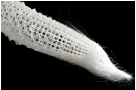
Euplectella (Figure 3) one of the most inspiring natural glass creations, are living creatures found at the bottom of the ocean, animals whose body structure is composed entirely of silica. The body structure of this natural living thing, resembles an artwork made with glass fibber threads.
Figure 3. The dried siliceous skeleton of the deep-sea glass sponge, Euplectella. Randolph Femmer, USGS. Public domain.[13]
Another living creature made of glass exist as Diatoms unicellular algae. These are the only organisms on earth with cell walls made entirely from silica. These amazing creatures in addition to constituting an inspiration to humans from Nature, are of extreme importance to the world's
ecosystem, it is estimated that diatoms contribute 40 - 45% of oceanic primary productivity, are responsible for 20% of global carbon fixation and oxygen production.[14]
Figure 4. Diatom. Division chrysophyta, 15 microns, Monterey Bay Aquarium [15]
Figure 5. Melosira sp.(left) and Launderia Annulata (right) Collected during the tara oceans expedition 2009-20012 Christian Sardet, Jennifer Gillette and Chris Bowler.[16]
It’s‘ difficult nearly impossible to tell at first glance whether this photographic image (Figure 5) of Diatoms is a scientific research publication, or shows highly decorative pieces in glass manufactured by humans.
The same can be said of the following image Tektites (Figure 6) are a special kind of glass created as the result of the impact of meteorites on the earth's surface.One of the most intriguing types of tektites are Moldavites which exhibit a green olive or blueish green colour, found in the south of Germany resulting from a meteor impact 15 million years ago.[17]
Figure 6.Moldavite from Besednice, Bohemia, Czech Republic, H. Raab [18]
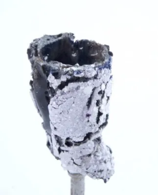
Finally, and in relation to this study, the most important type of natural glass, Fulgurites (Figure 7) are a natural occurring type of glass formed when lightning strikes the ground, fusing and vitrifying mineral grains[19], producing what is in fact, petrified lightning.
3.2. Fulgurites
3.2.1. How are Fulgurites Created?
A fulgurite is a glassy object that is made as a result of a cloud-to-ground lightning discharge. The term fulgurite comes from the Latin fulgur which means lightning.
The lightning peak temperature is considerably higher than the melting point of Silica, which is somewhere between 1600 and 2000 °C depending on moisture content. But whether or not silica sand melts and glass is produced depends, in addition to on other, not well-understood factors, on the lightning strike duration.
Some lightning strikes last (once contact with ground is made) less than a millisecond, others linger for a significant fraction of a second. Lightning current peaks are usually of the order of tens of kiloamperes, but occasionally may exceed 100 kA. The longer-lasting strike durations are typically in the range of tens to hundreds of amperes and it these that are thought to be responsible for producing fulgurites.[21]
As previously stated, quartz sand melts at temperatures between 1600 - 2000 °C depending on moisture content, and molten glass is then pushed to the periphery of the void. Subsequent relatively rapid cooling causes the glass to solidify.
A general condition for sand fulgurite formation appears to be the presence of a relatively dry dielectric such as when quartz sand lies over a more conducting soil layer or the ground water table, with the depth of the latter probably determining the limit for vertical extent of the subsequent fulgurite formation, exhibit chemical and morphological alterations caused by heating during the lightning strike. Fulgurites may vary in size, from < 1 cm up to several meters and many fulgurites are cylindrical or elongated conically.[22]
When lightning strikes sandy soil, (Figure 8) the air and moisture present in soil are rapidly heated, and the resultant explosion-like expansion forms the central tubular void.
3.2.1. Lightning
Greek myths held the god Zeus responsible for sending rain and lightning to earth; sometimes he aimed his thunderbolts at misbehaving mortals. According to the Navajo in the American Southwest, lightning sent by offended gods could, in addition to killing sheep or destroying the Navajo’s dwellings, cause disease. Whether regarded as the wrath of an angry god or an electrical discharge, lightning is a phenomenon feared equally by most peoples, ancient and modern. And for a good reason. [24] On average, about 100 lightning discharges occur every second on Earth, but only about one-third of them involve ground (others occur within the cloud, between clouds, or between cloud and clear air). The ground strikes potentially can make fulgurites, each cloud-to-ground lightning strike carries an energy of roughly 10# - 10$% Joules most of the lightning energy is spent producing thunder, hot air,
light, x-rays and radio waves, so that only a small fraction of the total energy is available at the strike point. The peak temperature of a lightning is of the order of 30,000 K, which is five times higher than the surface temperature of the Sun.[25]
3.2.2. How is Lightning Generated?
Lightning is a sudden electrostatic discharge, where the electrical potential of different regions of the atmosphere and earth are equalized.[26]
The equalization occurs thanks to the opening of current paths. These paths are created by the ionization of the molecules and atoms composing the atmosphere.[27]
This ionization only occurs at the breakdown voltage (see section 3.3.6) of the isolating media, in this case the atmosphere itself.
When the current traverses the ionized air and media through which the lightning travels, the air becomes superheated creating an ultra-fast expansion of the gases which in turn generates a shock wave which we call thunder.
When the current traverses the ground, the materials in the ground undergo extreme heating -due to the resistivity of the ground to the high current passing through it- as expressed in the following equation: (Joule heating or Ohmic heating) [28]
& = ( × +
,Where P is the power dissipated into heat, I is the current, and R is the resistance of the medium. All these three terms will be explained in the following sections.
When the temperature of the ground medium rises above its melting point, the lightning strike create what we call fulgurites. These are melted and reformed zones of the lightning-stricken medium where the temperature exceeded the local melting temperature.
3.3. Electricity
3.3.1. Electrical Current
Electrical Current is the movement of charged particles in one specific direction due to the electrical field, the charged particle can be an electron or a positive or a negative ion. The basic unit of electric charge is the Coulomb which corresponds to the charge of 6,25 × 10$1electrons.[29]. In electricity the
quantity of current is specified in terms of charge flowing per unit time.
2344567 (+) =
:;<=>? (@)ABC? (D)(I)=
(@)D,
The basic unit of current is called Ampere (A) equal to one Coulomb of charge flowing per second.[30]
3.3.2. Electrical Voltage or Electrical Potential Difference
Voltage is the electric pressure caused by the circulation of current, also known as the electromotive force (emf). A Volt (unit of potential difference and of electromotive force) is the potential difference between two points of a conducting wire carrying a constant current of 1 ampere, when the power dissipated between these points is equal to 1 watt.[31]
E=
FGD?HDB<I ?H?=>J K;<=>?=
L :=
M>.CO P.Q R3.3.3. Electrical Resistivity
Electrical resistivity is a fundamental property of a material that quantifies how strongly that material opposes the flow of electric current [32], the unit used to specify the value of resistance is the ohm (Ω), which is defined as the value of resistance that allows 1A to circulate when the tension is 1V.[33] Ohm's Law
2344567 (+)=
SGID<>? (S)T?QBQD<HK? (Ω)
I =
S T
3.3.4. Electric Transformer
A Transformer (Figure 9) is a device which transfers electric current from one circuit to another, usually by the principle of mutual induction. During this process, the frequency remains constant whereas the voltage can be increased or decreased as needed. The transformer requires alternating current to operate
This transfer of electricity occurs with the use of two coils. One known as the Primary Coil, connected to a source of alternating current. The other known as the Secondary Coil, and it is connected to an external circuit.
Figure 9. Circuit diagram of a transformer.[34]
3.3.5. Electrodes
Electrodes are electric conductors usually made of metal, used as either of the two terminals of an electrically conducting medium; it conducts current in and out of the medium, which may be an electrolytic solution as in a storage battery, or a solid, gas, or vacuum. The electrode from which electrons emerge is called the cathode and is designated as negative; the electrode that receives electrons is called the anode and is designated as positive.[35] Due to their ability to apply a voltage from one source to another medium, electrodes are extremely versatile and several different types have been created to meet a wide variety of needs.
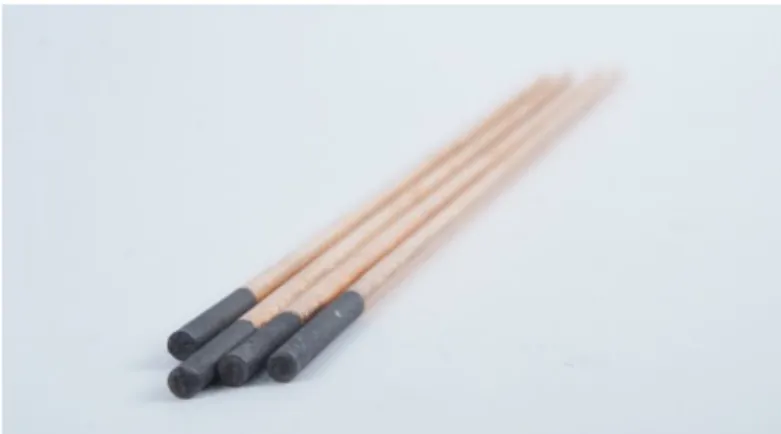
Electrodes are usually made of metallic compounds due to their high conductivity but they do not need to be metallic in all cases, there are several types of materials that can be used for electrodes, even glass electrodes that among other purposes, are used in neon lighting, exist. For the purpose of this thesis work Carbon electrodes (Figure 10) have been used due to the very high temperatures needed to melt glass.
One very common use of electrodes is in welding, which in principle is similar to the process used in this thesis to melt glass. One needs to apply a potential difference (voltage) between the two electrodes but it's also necessary that the current can flow through the electrodes owing to the need for a high current in order to increase the temperature to melt glass.
Figure 10. Graphite Copper coated, Gouging electrodes.
3.3.6. Electric Arc and Breakdown Voltage
An electric arc is the creation of current paths in a medium, commonly a gas. The current creates an elevation of temperature in the gaseous medium which produces a plasma and light emission. As in a lightning the initial path is created by the ionization of the molecules and atoms in the medium - occurring when the applied voltage exceeds the breakdown voltage. The fast acceleration of the newly freed charges increases the collision rate with neighboring molecules along the path of the accelerating charges. These collisions not only help free new charges and particles which will end up composing a plasma - but also increase the average kinetic energy of the particles and therefore the temperature of the medium. Because of this, there is a subsequent emission of light.
The breakdown voltage is the voltage at which the first electrons in an otherwise insulating material are freed. Thereby making the material conductive. The breakdown voltage of a gas can be
calculated using the following equation:
[36]
Where p is the pressure of the gas, d is the distance of the electrodes, and A, B and γsc are constants of
VWX the material. The breakdown voltage depends on many parameters of the material to which the voltage is applied. The distance between the electrodes is a very important parameter for the experiments conducted and named in this thesis because that distance determines for any given applied voltage what the electric field between the electrodes is. Using the simplified equation:
and knowing that the force that an electron would experience is
F = E.q
we can see how for a smaller distance, with a given voltage, the electric field is stronger and therefore the forces on the charges are also stronger, to the point that the applied electric force is stronger than the force from the nucleus that keeps the electrons in the atoms and molecules together.
As we already indicated, this is the process that occurs naturally in lightning but it can also be artificially created by applying high voltages across insulating media. E.g. gases - this is the basic underlying principle of the neon bulb - but also in solid materials.
3.3.7. Plasma
As we already saw when we can strip the electrons from the atoms, the charges are free and therefore constitute a different state of matter, with different properties than the original composing material used to create the plasma - Since the properties of matter are determined by the whole interaction of nucleus and electrons-. Plasmas are then a mixture of charges positive and negative which are not bound to each other. We can create these plasmas both by heating a material to very high temperatures, as in the case of the sun or in certain parts of a hot flame. Or we can also create a plasma by applying a strong electric field capable of stripping the electrons from the atoms, as in the process I researched. When the plasma is hot, that is, the components of the mixture are moving around at relatively high speeds and colliding with charged and neutral particles of the plasma mixture, so that on average all the particles have a high kinetic energy, these collisions and movements can result in the emission of light.
In our experiments we see light from the arc discharges evidencing the creation of plasmas as shown in Figure 11.
3.3.8. Glass Electrical Conductivity
Glass is mostly silicon dioxide which is a covalent compound that shares electrons from each of the constituent elements (silicon and oxygen) to bond those elements together as a compound, two atoms of oxygen for each atom of silicon. Some glasses have additions of ionic compounds, the conduction of electricity requires some free electrons that allow charge to move through the material. Electrons in covalent and ionic compounds in glass are too tightly bound to the molecule to conduct electricity. This is one of the reasons why glass is not good at conducting electricity and is considered an isolator.
At room temperature, glass can be viewed as consisting of a giant and continuous three dimensional network of silicon and oxygen atoms connected by strong covalent bonds. Interspersed between them are positively-charged sodium and calcium cations that are held in place by ionic bonds. They are bonded to charged oxygen atoms hanging off the silicon-oxygen chains that compose the network. Everything is held firmly in place because all the chemical bonds are so strong. This is what makes a glass overall a rigid material. The kinetic energy that all the atoms have is largely in the form of vibrations.[37]
If glass is warmed, some of the weaker chemical bonds break (those which are somewhat distorted because the glass has not formed into a regular, symmetrical, crystalline lattice). Thus, the glass begins to soften slightly. As the temperature is increased further, the next weakest bonds break, and the glass becomes still softer. At some point, the structure has collapsed to the extent that the positively charged cations (Na+, K+, Ca++, Fe+++, etc.) can break free and become mobile. This means that they can move through the softened glass. The motion of the charged species constitutes electrical conduction and redox reactions can then occur at the electrodes that are imposing the electric field. As the glass becomes hotter, it becomes more fluid (its viscosity decreases) and the ions can move more readily. Thus, in contrast to metallic conductors, the conductivity of the softened glass increases with temperature, instead of decreasing.[38] As seen in the following table. Glass has a resistivity of about 790 Ωm at a temperature of 1500 oC.
4. Experimental Design
The experiments carried out in this thesis are meant to explore the conditions necessary for the development of a method that would allow electrically formed glass to be formed in a controlled way. The idea is to find a novel and fast way to form glass using electricity. This results in a process where no flux is needed, by using an electrical transformer that produces high energy plasma which delivers sufficiently high temperatures so that there is no need for lowering the melting temperature of SiO2
with fluxes.
The use of high current in glass forming was studied, followed by experimentation with high voltages. When using a system of high current and low voltage the necessity for physically joining the
electrodes in order to overcome the breakdown voltage and create the arc, resulted in a drawback of the system. It is relatively more difficult and dangerous to operate the system by hand i.e. manually moving the electrodes together to cause the arc, instead of a on/off system which is made possible when using high voltage, so that experimentation with a high voltage transformer was then indicated .
4.1. Initial Setup Design
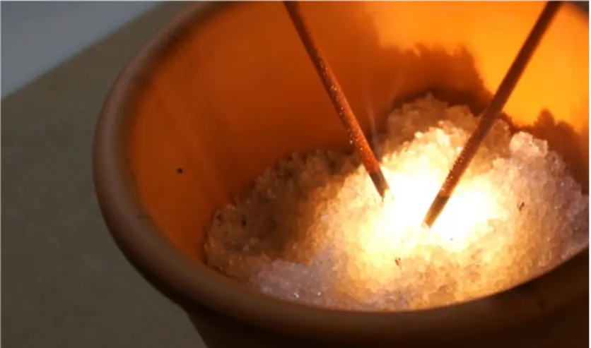
The first step in the experimental Design was to become an “art-researcher”, i.e. to develop my own machines exploring Art and Science by using my previous experience and knowledge to learn, and to develop my own methodology. I developed a functional set up that would allow me to melt silica powder in a directed fashion, (Figure 12) exploring with my own hands the possibilities of the technique I employed an electrical transformer used for welding, and carbon electrodes creating a process which generates enough heat through a plasma arc to melt diverse silica- based compounds creating vitreous structures.
The initial set up consists of a welding transformer CEVIK CE-K140T with an output Tension of max, 48 Volts, and a regulated current field between 60-140 Amps [40]. The electrodes I employed are Gouging electrodes,Copper coated Graphite electrodes of 4 mm diameter by 250 mm in length commonly used in the metal industry for cutting, removing welding defects, making holes, welding inspection, and removing over-welded parts [41]. The choice to use graphite electrodes was made because Carbon sublimes in a carbon arc which has a temperature of around 5800 K (5,530 °C or 9,980 °F).[42] Carbon remains solid at higher temperatures than the highest-melting-point of metals
e.g. tungsten. In this set up I used a terracotta ceramic plant pot resistant to high temperatures to contain the different substrates used for this experiment.
Because of the very high temperature reached, it was not possible for me to measure the arc’s temperature with the available equipment, (IMPAC infrared thermometer which measures
temperature in a range between 150℃ to 1800℃). In order to have an estimate of the temperature reached with the transformer at the tip of the electrodes during my experiments, I assumed an arc temperature varying between 2482℃ and 3594℃ (Licoln Electric).[43] from literature.
Figure 12. Initial set-up.
4.2. Arc Displacement
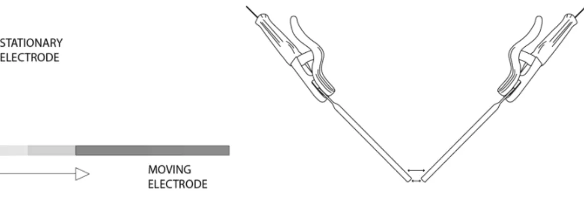
Following the experimental design, and once a working setup was achieved It became possible to experimentally explore the effect of the plasma arc in Silica powder, those experiments focused on the different currents it was possible to obtain from a welding transformer with a range between 60 to 140 A, in correlation with variable movements of the electrodes (Figure 13) in the substrate and the time the arc could expand to form artificial fulgurites.
Figure 13. moving electrodes.
This procedure once initiated, demonstrated that it was first necessary to touch the electrodes with each other inside the substrate in order to generate the plasma Arc. Once this happened and the electrons could flow freely across the substrate, the electrodes were slowly pulled apart from each other in order to melt the various compositions I tested.
Continuing the experimentation with electrically formed glass, once the procedure allowed for making artificial fulgurite samples, I investigated the result of employing different materials and silica-based compositions to research possibilities this technique for glass manufacture. (section 4.8.)
4.3 High Voltage MOT Power Supply
As explained in section 4.2. when using a high current - low voltage source, the procedure to create fulgurite begins by making contact between the electrodes the physical contact of the electrodes allowing to overcome the breakdown voltage and start the arc through which the high current is transported. Although such a system allows the quick formation of pieces of glass with a determined form by hand directly from the sand, it has the drawback that it is difficult to automate, because the starting procedure requires touching the electrodes, then separating and maintaining a given distance between them during the melting of the glass. Although it is possible to digitally steer the mechanism the ideal set up is one where the arc can ignite by itself despite the distance between the electrodes this is possible by employing a high voltage power supply instead. For this reason, I then tried to imagine and create a different setup where the voltage used would be higher than the breakdown voltage without the need to change the electrode interspace.
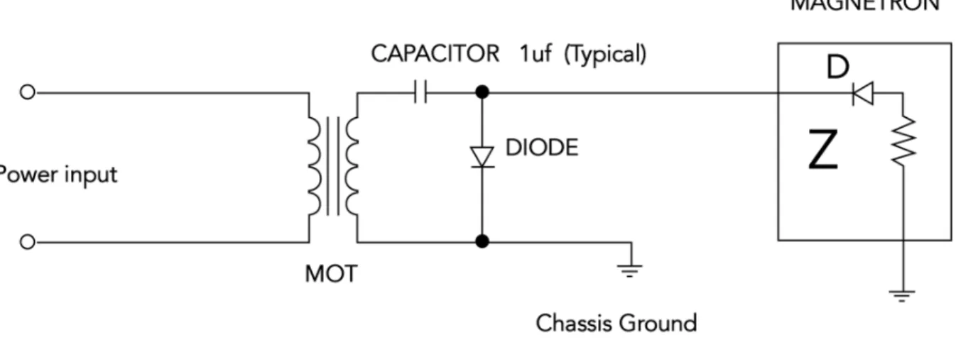
For this second setup I used a MOT (Microwave Oven Transformer) in order to achieve a high Voltage across the samples. A MOT used in conventional microwaves can deliver an output voltage ofbetween 1800 - 2800 volts (average ~ 2200 volts) [44] for the purpose of this experiment the circuit
of a microwave had to be modified. (Figure 14 -15)
Figure 14. This is a scheme of the basic high voltage power supply circuit found inside the typical microwave oven.[45]
Figure 15. Modified MOT.
In order to use the MOT as the power supply for glass-forming, the above circuit was modified removing the
Magnetron, while maintaining the security features of the microwave for safety reasons.
4.4. Ignition System
The ideal system is to have an ignition for the arc at a high enough voltage to break down the
resistance of air between the electrodes at a distance of 5 mm. For this purpose, a system (Figure 17) with a small high voltage generator of 3kV was employed in conjunction with the high current
transformer system as shown in the following diagram.
Figure 17. Ignition system.
transformer and the high voltage generator, it was necessary to add to the circuit a series of transistors to be able to work with both high current and high voltage at the same time. Commercial transistors are built to handle either high voltage or high current It was therefore necessary to use a special type of transistor known as IGBT, but these transistors are prohibitively expensive so that it was not possible for me to investigate that system. Therefore, a method of physically joining the electrodes to create the plasma arc was adopted in the following experiments,
4.5. Flat Electrode
Electrodes are used to deliver the electrical power to the sample. Both the shape and the composition of the electrodes determine the electrical power output required. For the purpose of this study, carbon electrodes were used. Because the idea is to achieve a system that allows for mechanizing the procedure, a test with a flat graphite electrode was undertaken. The theory is that by conducting the electricity from a moving cylindrical shaped electrode across a flat electrode, it may be possible to ‘draw’ shapes on the substrate.
Two tests, one with high current at 120 A and 42 V, and a second one with high Voltage ~ 2200 V and 0,5A were carried out on a silica substrate layered on top of the flat electrode. (Figure 18)
4.6. Circular Motion Printing
In order to begin a test for mechanizing the system of printing with electrically formed glass a system to print in a circular way was tested as shown in the Figure 19. The system consists of a biaxial mechanism allow whereby the electrodes to remain stationary while rotating the substrate under them and at the same time varying the vertical distance between the electrodes and substrate. In this way, I attempted to print a cylindrical form in glass.
Figure 19. Circular motion 2 axis print system.
4.7. Silica Dough Extrusion System
In the previous experiments it was noticed that an increase in moisture was conducive to inducing the plasma arc in the substrate,resulting in increased conductivity and better results. For that reason, a procedure for extruding a paste mix of silica and water through a thin nozzle was tested. (Figure 20) The idea behind this procedure is that by depositing a thin extrusion of Silica paste between the electrodes, perhaps the balling up of melted glass attached to the electrodes observed in previous experiments could be avoided.
4.8. Investigated Substrates for Artificial Fulgurites
4.8.1. Material Test
Sample 1.a - Sand Sample 2.a - Perlite
Sample 3.a - Pure Silica
Sample 4.a - Furnace Glass
Sample 5.a - Borosilicate Glass
Sample 6.a - Recycled Bottle Glass
4.8.2. Portuguese Sands
Samples of sand collected in different locations within Portugal were tested for making artificial fulgurites using 140 Amps and 42 Volts, creating an arc of 10 seconds for each sample following the procedure described in section 4.2 the experiment was repeated 3 times for each sample.
Sample 1.b - Pantes de Maiorca Sample 2.b - F.Roz Cetari Sample 3.b - Aldeia Viçosa Sample 4.b - Couveia Mangualde Sample 5.b - Taveiro Coimbra Sample 6.b - Barragem da Aguieira Sample 7.b - Termas de Felgueiras Sample 8.b - Moinho Almoxarife Sample 9.b - Ratoeira Celorico Sample 10.b - Porto da Carne Sample 11.b - Vale de Canas 1 Sample 12.b - Vale de Canas 2
Sample 13.b - Praia Fluvial de Ribamondego Sample 14.b - Vale do Rossim
Sample 15.b - Pereira do Campo Montemor
4.8.3. Portuguese Sands with Analysed Compositions
Sample 1.c - Monte Redondo Sample 2.c - Alhadas
Sample 3.c - Praia da Vieira Sample 4.c - Agueda
4.8.4. Silica Based Compounds
Sample 1.d - Silica and Cobalt Oxide (SiO2 + CoO)
Sample 2.d - Silica and Chromium Oxide (SiO2 + Cr2O3)
Sample 3.d - Silica and Manganese Oxide (SiO2 + MnO2)
In order to maintain structural integrity of the samples, all the specimens listed above were annealed with the annealing temperatures used at Vicarte for the soda-lime glass used in their furnace. The samples I produced were held at 485°C for 2 hours, going down to 370°C in 5 hours, holding at 370°C for 45 minutes and finally lowering to 30°C in 4.5 hours.
5. Results and Discussion
5.1 Artificial Fulgurites with Different Compositions
When the plasma is created in the substrate, the arc will stop if the electrodes are moved away from each other rapidly. But when they are moved from each other more slowly, the arc can be maintained at a greater distance. This results from the effect of electrical conduction in glass as seen in (Table.1). The electrical conductivity of glass is proportional to its temperature, so that the longer the plasma arc acts on the sample, the higher its conductivity, allowing for bigger artificial fulgurites.
Electrons flow across the substrate until the resistivity becomes so high that they cannot flow
anymore (Figure 21). That variable is what limits the size of the artificial fulgurite formed, so that it can be experimentally determined which substrate is more conductive.
Figure 21. Sand Artificial fulgurite made with 120 A.
Figure 22. View Inside Hollow Sand Artificial Fulgurite 120 A.
The fulgurites produced were hollow (Figure 22) as are natural fulgurites described in the section 3.2.1. That results from the presence of moisture inside the sand, so that the vapours expand “bubble-like” shape very similar to the forms created when blowing glass.
5.1.1. Material Test
Samples of different glassy substrates were made using the method of arc displacement at 120 A 42 V for 15 seconds for each sample.
Figure 23. Material Test Samples.
The results achieved with tests made with different materials (Figure 23) resulted in interesting vitreous shapes of different characteristics: Borosilicate, Furnace Glass, Perlite and Recycled Bottle Glass, which were already glassy structures before the experiment, melted when exposed to the plasma arc. Fused together in solid forms, Perlite was very plastic while the rest of samples were relatively stiff when manipulating the electrodes inside them. Borosilicate manifested as a good material to “draw- with”, showing promise as the choice for a future printing method.
The samples made with Sand and Silica powder are hollow inside, just as natural fulgurites are. The sand sample had more structural integrity than the sample made only with SiO2, which had paper-thin walls.
5.1.2. Portuguese Sands Fulgurites
Artificial fulgurites made with Portuguese sands using the method described in section 4.2 (120 A 42 V - 15 Sec arc) (Figure 24).
5.1.3. Portuguese Sands with Analyzed Compositions
Figure 25. Sand fulgurites with composition.
Analyzing the structure of the fulgurites formed using sands from 1.c Agueda, 2.c Alhadas , 3.c Monte Redondo and 4.c Praia da Viera shown in Figure 25 demonstrated that while applying the same Current 120 A and voltage 42V and using the same production method (section 4.2), the samples made with sand from Agueda were comparatively smaller in size and weight than the other samples. Sample 4.c made with sand from Praia da Viera formed a larger fulgurite. It is hypothesized that conductivity of this sand is higher than that in the sands used for samples 1.c, 2.c, 3.c.
Figure 26. Density Sand Fulgurite Samples with Composition.
Analyzing the density of the samples 1.c, 2.c, 3.c and 4.c, (Figure 26) the sample made with sand from Praia da Viera (sample 4.c) has the highest density; 1,48x10⁻³kg/m3. It is the sample that has formed the highest amount of Glass compared to the other samples. In relation to its composition (Figure 25) sample 4.c has the highest concentration of SiO2, c.q 94%, and also has the highest
content of CaO at 0,93% It could be that the amount of Calcium influences conductivity of the substrate, leading to the electrical formation of more glass. This relation between calcium concentration and the size of the electrically formed sand fulgurite should be further studied. The sample made with sand from the region of Agueda sample 1.c, has the lowest density of all 4 samples analyzed with an estimated density of 1,3x10⁻⁴kg/m3, compared to the other samples 2.c Alhadas at 3,9x10⁻⁴kg/m3 and 3.c Monte Redondo at 4,3x10⁻⁴kg/m3. In terms of composition the most noticeable differences, that might explain why the sample (Agueda 1.c) formed the least glass, are that 1.c presents the lowest percentage of SiO2 with 92,2% and the higher presence of Al2O3 with
5,1% of its total composition that could be one factor that affects the formation of glass by this method of electrically formed glass, further investigation needs to be carried out.
5.1.4. Silica (SiO
2) + Metal Oxides
Figure 27. Samples (SiO2 + Metal Oxides).
The samples made with SiO2 combined with Cobalt, Manganese and Chromium oxides (Figure 27)
resulted in artificial fulgurites similar in terms of structure distribution, the 3 samples are hollow fulgurites. the 3 samples 1.d, 2.d and 3.d presented thicker walls than when using only SiO2.
When Cobalt oxide is used the samples are thicker than when only using SiO2, SiO2 + Cr2O3 and SiO2 + MnO2, it appears that adding Cobalt oxide (CoO) increases the conductivity of the substrate,
allowing for more glass formation. This effect was also observable during the process of forming the fulgurite, the arc lasted longer and was easier to extend.
In figure28 can be seen that the inner part of the fulgurites present a glassy surface, the SiO2
samples appeared very transparent. As expected, the Cr2O3 composition resulted in a green glass,
MnO2 purple and CoO in cobalt blue glass.
Silica and cobalt oxide gave the best results for artificial fulgurites, resulting in very structurally stable samples of greater thickness.
5.2. Material Characterization
In all samples made with the copper coated carbon electrodes, it was noticed that the result samples present a red pigmentation most likely due to Copper presence in an oxidized state. [46]
By employing copper coated electrodes metallic copper Cu0 forms colloidal aggregates manifesting the red color of copper Ruby[47] on the samples.
Figure 29. Red colour in SiO2 Sample.
All samples made presented red pigmentation, likely due to the presence of copper in the coating of the carbon electrodes. For this reason an x-ray fluorescence analysis was made on a sample of only Silica powder (SiO2) in composition, searching for copper. In order to confirm the hypothesis of Copper being the element that attributes the red ruby pigmentation to the sample a XRF Analysis was made to one sample of only SiO2 in composition (Figure 29). As well as to the Raw material used for
the experiment, with the expectation that copper would not be indicated in the analysis made to the Silica powder (SiO2) sample.
5.2.1. XRF Analysis
A sample of an artificial fulgurite made with SiO2 presented red pigmentation, likely attributable to the
presence of copper in the coating of the carbon electrodes. For this reason, an X-ray fluorescence analysis was made on this sample produced, looking for copper. To compare results an XRF analysis on the silica used for the production of the sample was made, (Figure 30) in the expectation that copper would not be indicated in the substrate material.
Figure 30. XRF SiO2 Sample and Raw Material.
Through X-ray fluorescence analysis carried out on one sample of SiO2 powder subject to a high
current electric discharge in comparison to the Raw Material used, it was determined that there is an absence of copper in the Raw material. Confirming the hypothesis that the red colour found in all samples resulted from the presence of copper as a constituent of the coating of the carbon electrodes.
The XRF analysis made to the ‘pure’ SiO2 sample (figure 30) show the presence of other elements,
Ca, K, Ti, Al and Fe, this ‘contamination’ was somehow expected because the silica powder used as raw material was silica sold commercially for making art molds. As a result of the production process for that material, there is no certainty that it is pure Silica. Another possibility is, contamination during the production process of the samples I made. These were made in an art workshop environment, one subject to many sources of contamination.
5.2.2. Raman Analysis
A Raman spectroscopy analysis was made of three samples produced following by the procedure developed in chapter 4.2.
Samples with composition, SiO2, SiO2 + CoO, SiO2 + Cr2O3, were analyzed (Figure 31) looking for
silica amorphous bands and possible quartz bands that were expected to have been synthesized due to the high temperatures reached with the plasma induction on the samples.
Spectra were collected using a Jobin Yvon-Labram 300 spectrometer, a 532 nm laser, a 50x objective and a power of 0.35 mW.
Figure 31. Raman SiO2, SiO2 + CoO, SiO2 + Cr2O3
In the collected spectra (Figure 31) there is no evidence of structural differences between the samples, given that the addition of metal oxides to the silica matrix is less than 2% of the total compositions in all samples.
Figure 32. Raman SiO2, Amorphous Silica.
The spectra taken from the SiO2 sample was normalized and compared to the database for
Amorphous Silica,[48] (Figure 32) evidencing that the sample produced, matches exactly the database spectra. The wavelength bands indicated through this analysis at, 447, 494, 607, 809 are
characteristic of amorphous silica [49] and demonstrates the absence of crystalline structures.
5.2.3. Natural Fulgurite Raman Analysis
Out of curiosity to compare the previous analysis made of the artificial fulgurites, a Raman spectroscopy analysis was made of a naturally produced sample of a real fulgurite specimen of unknown origin (borrowed from professor Mário Ventim Neves, Área Disciplinar de Energia FCT) (Figure 33). The spectra (Figure 34) taken from the sample was normalized and compared to the database for Crystalline Silica[50], evidencing that the sample produced, matches the database spectra with a band at 464Z[ \$characteristic of SiO2 in quartz form[51]. The presence of quartz structures i.e. crystalline structure in the fulgurite can be due to the very high temperatures the fulgurite was subjected to during its process of formation. One another possibility is, that because to avoid damaging the specimen, the sample taken from the fulgurite to carry out the analysis was from the outside crust, that part of the fulgurite retained the crystalline structure characteristic of quartz. As can be seen in the image figure 33, the crust appears to be covered in sand that had fused to the inner core, and this would explain why the spectra show Raman bands that indicate the presence of quartz. Further analysis should be made of the inner core of the fulgurite sample to look for the presence of amorphous silica structure.
5.3. MOT High Voltage Transformer
Figure 35. MOT Experiment.
When using the MOT transformer for a long period (more than 10 minutes) the transformer overheats due to high current output. The transformer must therefore be turned off and allowed to cool to avoid damaging it. This type of transformer won't allow for a continuous printing system, i.e. automated production.
The method followed and described here, allows for a very easy start, because the high voltage approximately 2.2Kv with a distance of about 2 mm between the electrodes, is enough to exceed the breakdown voltage of air, thus generating an arc without the need to physically touching the
electrodes, making it a safer procedure for a future glass printing system.
The result of the print obtained is uneven, the consistency of the thread produced by this method is not yet constant (Figure 35) due to a balling up of the substrate that melts between the electrodes. This results in a sequence of printed balls, which then causes the plasma arc to jump from ball to ball, therewith finding the easiest conductive path for the electrons to flow.
With the method employing a High Voltage MOT transformer with an average output voltage of 2.2Kv and 0,5 A it was found that clearer glass was produced when compared to the samples produced using high current.
When employing the high voltage method, the electrodes have to be kept at a shorter distance from each other, because of the low current available from the transformer 0.5 A, therefore the space between becomes so small that, when sliding the electrodes through the substrate glass forms and clusters in between the electrodes, creating increased resistance to electron flow.
5.4.
Circular Motion Printing
Figure 36. Circular Motion Printing sample SiO2 Powder.
The continuity of the print using a method of circular motion printing with a high current transformer, with an output of 120 A when applied on SiO2 powder results, in a continuous print of hollow nature
(Figure 36). The moisture naturally present in the substrate, when subjected to the high current plasma arc results in vapours that expand the printed surface, producing a hollow structure as occurred in the previous experiments of artificial fulgurites production.
The high viscosity of the molten glass results in an increased difficulty to move the electrodes across the powder.
Interspacing of the screw thread used within the mechanism to rotate lift and lower the substrate, shown in Figure 19 needs to be matched to the size of the print in order to print 3D.
5.5. Silica Dough Extrusion System
Figure 37. Clear Sample Vitreous Silica 1 cm
The trial to print wet silica SiO2 with a ‘dough consistency”, extruded through a thin nozzle ‘syringe,
explained in section 4.7, with a high voltage MOT power supply with an output of approx. 2.2Kv resulted in a very transparent high-quality vitreous silica print. (Figure 37)
The continuity of the printed thread was more stable than in previous attempts. This trial resulted in a small 1 cm consistent print.
6. Conclusions
-The experiments undertaken and described here, allowed me to electrically form vitreous silica from SiO2 powder in a very fast and inexpensive way, with no need for a flux. Using an electrical
transformer produces high energy plasma which can deliver sufficiently high temperatures so that there is no need for lowering the melting temperature of SiO2 with fluxes.Further study in this method
is indicated, given the importance of vitreous silica for the industry, due to its properties and functional efficacy. Further experimentation could result in the development of a system to print complex shapes which are now difficult to obtain with current techniques, in a fast and cost-effective way.
-Through the experiment that involved forming artificial fulgurites made with several sands collected from different regions of Portugal it was possible to demonstrate in small scale, the otherwise very unlikely result of a lightning strike in any and all of these regions.
-By employing copper coated electrodes, metallic copper Cu0 forms colloidal aggregates manifesting the red color of copper Ruby on all samples made with this the method. This may perhaps constitute an affordable way to obtain Ruby red in glass.
-Electrically forming glass from silica SiO2 in powder form alone, and with the addition of metal oxides
SiO2 + CoO, SiO2 + Cr2O3, using a current of 120 - 140A and 42 V results in the formation of amorphous silica with variations in colours but not in structure. Crystalline structures do not form when the method described in this thesis is followed.
-The presence of higher amounts of Calcium oxide CaO in the composition of the substrate could affect the formation of glass reducing the efficiency of the plasma arc. Further study would need to be carried out to verify this theory.
-It appears that adding Cobalt oxide (CoO) increases the conductivity of the substrate forming more glass during the experiments, resulting in thick glass walls, and thereby more structurally stable samples. Further study should be undertaken.
-When applying a system of two parallel electrodes to induce a plasma arc in a SiO2 substrate, the
viscosity of the molten glass once the substrate begins to fuse, represents a difficulty for mechanizing the system. The glass formed tends to ball-up and stick to the electrodes, inhibiting controlled printing. For future development I suggest the design of new electrodes that allow an increase in the
interspace distance, and thereby avoid the agglomeration of the substrate, so that the plasma arc can form the glass in the desired way.
-The test employing a stick carbon electrode on top of a flat carbon electrode covered with the substrate attempting to print on a flat surface, does not work correctly. Trials were made with both; (high current / low voltage) and (high-voltage/ low current), and in both scenarios, these tests were unsuccessful, because the arc was not constant. This, I concluded, was due to the flatness of the electrode, making the electric field lower since that field becomes distributed over a larger area. Because the electrical field determines the ionization of the atoms in the atmosphere and in the glass, being smaller, the arc was less constant and did not allow for drawing shapes on the substrate. -The use of high current in glass forming, effects the fusing of SiO2 powder rapidly. The glass is most
purposes, for example in producing art works, the ‘opaque quality’ of the glass may not at all be a problem. And the cost-effectiveness of this method, if interesting forms are achieved with it, already indicates fruitful results. Further tests are needed to determine the correct Amperage for the transformer in order to avoid burning the glass.
-For future development of a printing system, the method developed where Silica SiO2 powder high in
moisture in a dough consistency is extruded through a thin nozzle between the carbon electrodes, seems indicated. That procedure avoids the clumping together of the substrate, and with a high-voltage transformer, a successful clear vitreous vilica print was achieved (Figure 37).
-This work allowed me to gain far more understanding in the areas of glass and electricity. In order to develop a thesis focused on electrically formed glass I had to understand the variability of electricity behaviour when high voltages are applied since most of the experiments that I carried out were extremely dangerous. The danger aspect of this thesis although In some ways presented an obstacle to obtain better and faster results, allowed me to focus in every movement and experiment made. Learning to be meticulous and patient. It also served me to realize the vast possibilities of ‘playing’ within the fields of Art and Science, I learnt from an individual perspective to not follow the already established path of glass making but rather open my mind to new possibilities that can eventually become novel developments.As a person who comes from a previous study in Industrial Design the scientific world and its methods seemed very intriguing to me, throughout this experience In Vicarte and this Thesis work I had the chance to position myself within these two worlds, Art and Science, I’ve realized I'm neither an Artist or a Scientist, I'm somewhere in between, an explorer of possibilities, an inventor who will always be inspired by nature and by good people.
7. Appendix
FINAL EXHIBITION “CURRENT WORKS”
USALMA Galeria 2nd floor (Rua da Cerca 21, 2800-050 Almada)
8. Bibliography
1. Trungpa. Chogyam, “True Perception”, Shambhala, Kindle Edition, p. 378.
2. NLSI National Lightning Safety Institute, www.lightningsafety.com/nlsi_pls/probability.html, Retrieved 2019-04.
3. Mcfarlane. Alann & Martin, Gerry, “The Glass Bathyscaphe”, Profile Books, Kindle Edition. 4. James E. Shelby, “Introduction of Glass Science and Technology”, The Royal Society of Chemistry, p.3, 1997.
5.James E. Shelby, “Introduction of Glass Science and Technology”, The Royal Society of Chemistry, p.90, 1997.
6. James E. Shelby, “Introduction of Glass Science and Technology”, The Royal Society of Chemistry, p.214, 1997.
7. Arun K. Varshneya, “Fundamentals of Inorganic Glasses”, The Society of Glass Technology, p.2, 2006.
8. (Figure 2), Silicon Dioxide in Crystalline and Amorphous Forms,
www.ndt-ed.org/EducationResources/CommunityCollege/Materials/Structure/solidstate.htm, Retrieved 2019-04.
9. Center for NDE. Iowa State University, Resource Center,
www.ndt-ed.org/EducationResources/CommunityCollege/Materials/Structure/solidstate.htm, Retrieved 2019-04.
10. The Royal Society. "Christopher Merrett Biographical Information"
www.collections.royalsociety.org/dserve.exe?dsqIni=Dserve.ini&dsqApp=Archive&dsqCmd=Show.tcl &dsqDb=Persons&dsqPos=0&dsqSearch=(((text)=%27Christopher%27)AND((text)=%27Merrett%27)) , Retrieved 2019-04.
11.. Koinm. AJ, “Christopher Merret's Use of Experiment ,Notes”, R. Soc. Lond, p. 23, 2000. 12. Merrett. Christopher, “Observation on the Epistle to the reader”, in The Art of Glass. 1662. 13.(Figure 3), The dried siliceous skeleton of the deep sea glass sponge, Euplectella,
Randolph Femmer, USGS. Public domain,
www.usgs.gov/media/images/glass-sponge-euplectella-sp-0,Retrieved 2019-04. 14.The Microbiology Society,
www.microbiologysociety.org/publication/past-issues/real-superheroes/article/diatoms-glass-dwelling-dynamos.html, Retrieved 2019-04.
15.(Figure 4), Diatom. Division chrysophyta, 15 microns, Monterey Bay Aquarium,
![Figure 2. Silicon Dioxide in Crystalline and Amorphous Forms. [8]](https://thumb-eu.123doks.com/thumbv2/123dok_br/19217403.961091/11.892.258.637.489.830/figure-silicon-dioxide-crystalline-amorphous-forms.webp)
![Figure 4. Diatom. Division chrysophyta, 15 microns, Monterey Bay Aquarium [15]](https://thumb-eu.123doks.com/thumbv2/123dok_br/19217403.961091/13.892.197.696.108.389/figure-diatom-division-chrysophyta-microns-monterey-bay-aquarium.webp)
![Figure 7. Fulgurite, specimen from the Grand Erg de Bilma, Niger,10in height [20]](https://thumb-eu.123doks.com/thumbv2/123dok_br/19217403.961091/14.892.343.549.625.1073/figure-fulgurite-specimen-grand-erg-bilma-niger-height.webp)
![Figure 8. Fulgurite formation. [23]](https://thumb-eu.123doks.com/thumbv2/123dok_br/19217403.961091/15.892.271.621.810.1092/figure-fulgurite-formation.webp)