Abstract— Fiber-To-The-Home (FTTH) technology has been significantly implemented in access networks, providing very high data rates transmission and a variety of digital content to subscribers. It involves an optical cable link being installed between the building entry point and each subscriber with the Multiple Dwelling Units (MDUs), i.e. flats and apartments. In other words, optical cable has to lie fairly straight to carry a strong signal, since typically is necessary to bend, twist and turn the lines in and out of tight corners without degrading the link connection. In this paper we propose the use of Hollow-Core Photonic Crystal Fiber (HC-PCF) for FTTH applications. It is presented an experimental analysis of the macrobending effects in a HC-PCF based on a comparison with traditional fibers and by following the ITU-T G.657B standard recommendations. We observe this fiber, with only 6.5 m core, is bending loss insensitive, even at extremely small bending radius of 2 mm, in which it presents a loss of only 0.58 dB.
Index Terms—Fiber-To-The-Home, Photonic Crystal Fibers, Hollow-core (HC-PCF), Optical fibers and Bending loss.
I. INTRODUCTION
Photonic Crystal Fibers (PCFs),also known as microstructured fiber, has changed the ways of light
guidance within the fibers and opened new perspectives in the optical fiber technology[1-3]. These
fibers have a periodic wavelength-scale microstructure running along their length. Their core and
two-dimensional photonic crystal can be made from several geometries and materials, allowing light to be
guided thorough different mechanisms with a huge range of wavelengths, extending to the terahertz
regions [1].
Hollow-Core Photonic Crystal Fibers (HC-PCFs) are based on a periodic array of air holes in silica
glass cladding[4,5]. Unlike conventional fibers, in which light is guided by total internalreflection, in
a HC-PCF light is confined into a hollow core with low loss due to Photonic Bandgap(PBG) effect[4].
HC-PCFs have been shown very interesting for several scientific and technological areas, such as
development of gas-based devices [6], delivery of megawatt pulses [7], and generation of frequency
Applicability of low macrobending loss
hollow-core PCF to FTTH applications
D. G. Lona, H. E. Hernández-Figueroa
Departamento de Microondas e Óptica – DMO – FEEC – UNICAMP, Campinas – SP, Brazil. [email protected]
Arismar Cerqueira S. Jr., G. Stefanini
Faculdade de Tecnologia – FT – UNICAMP, Limeira – SP, Brazil. [email protected]
H. L. Fragnito
combs [8].Moreover, HC-PCFsallow light to be guided into core with low bending loss [9,10].In this
work, we evaluate the applicability of these fibers to FTTH networks according to the ITU G.657B
standard [11] by measuring its macrobending loss for very small bending radius and comparing its
performance to traditional single-mode fibers.
II. FIBER-TO-THE-HOME APPLICATIONS
Nowadays, the networks traffic is growing at speed never seen before. Current technologies provide
low cost solutions with high data rates that were previously not possible. However, most networks are
based on Asymmetric Digital Subscriber Line (ADSL), Hybrid Fiber-Coaxial (HFC) and wireless
technology. These technologies will not able to support future bandwidth demand due your physical
limitations, such as higher attenuation as frequency increase for more bandwidth. In addition, the
future broadband networks needs to offer triple-play solution.
The FTTH technology is becoming a reality for most people around the world, since it represents a
cost-effective solution for providing broadband services using optical fibers. These networks achieve
very high data rates with long distances, reaching up to20 km between customer and central office,
delivering data service, voice and video [12].
The increase FTTH deployment around the world in last year’s creates a new optical fiber area:
bend insensitive single-mode fiber [13]. These fibers are used to solve bending losses in installation
process. Furthermore, they can reduce the network costs and improve system performance [14].The
optical fiber experiences a series of bends during the installation process, mainly in Multiple Dwelling
Units (MDUs) in-home wiring, in which bending radius could reach up to 5mm [14].
Recently reports shows that to offers a robust FTTH network with a satisfactory performance the
bend insensitive fiber must accomplish 0.1dB/turn of optical loss at this bending radius [14].
However, standard single-mode fiber has an optical loss of 20dB/turn at this scenario, implying a
reduction factor of 200 [15] and making it a real challenge.
Therefore, several fiber design shave been proposed in order to solve this problem, such as:
reducing mode field diameter [16], depressed cladding [17], hole-assisted [18] and trench cladding
[15, 19]. The reduce mode field design is inefficient showing an optical loss of 2 dB/turn at 5 mm
bending radius [16]. Furthermore, the geometric change in core switches cutoff frequency,
zero-dispersion wavelength and slope zero-dispersion fiber parameters, not meeting the ITU-T G.652
requirements [15, 16]. F. Wu et al proposed to create a low index layer around the core, known as
depressed cladding design [17].This design offers a quiet more flexibility in set the fiber parameters.
However, it has the same performance as reducing mode field at 5 mm bending radius [17]. On the
other hand, the hole-assisted technique provides better performance than previous ones, staying near
the bending loss requirements. Otherwise, the most issue in this fiber design is the manufacturing
process because it is not suitable for delivering high fiber volume for FTTH deployments [18].
achieves 0.1dB/km optical loss at 5 mm bending radius [19]. Additionally, it is compatible with the
ITU-T G.657and G.652standards and can be manufactured using standard Outside Vapor Deposition
(OVD) [15].
Finally, the photonic crystal design uses 2D periodic array of air holes to allow light guidance with
especial properties that is impossible to obtain in conventional fibers, such low attenuation, bending
insensitive, high power levels and flat dispersion [1]. Moreover, up to date, there is no experimental
results showing Hollow-Core Photonic Crystal Fiber (HC-PCF) performance for FTTH applications.
For effectively employ HC-PCF in FTTH networks is also important that splice loss between it and
already installed optical fiber kept as low as possible. Theoretically, SMF-28 and HC-PCF splicing
could reach up to 0.48 dB [20]. Although, using a conventional splicer and optimized parameters
optical loss of 1.48 – 2.01dB were obtained with only one arc discharge [20]. However, these values
can be improved by mitigating splice parameters, multiple discharge arcs and combining fibers with
same core diameters [20].
FTTH applications use the Wavelength Division Multiplexing (WDM) technology. WDM
technology implies multiple channels in a single fiber, in which combined to optical amplifiers results
in extremely high optical powers, generally located at MDUs [14]. In these installations, as the level
of optical power and the radius of curvature increases a fiber degradation effect occurs, as know
fusion effect, in which optical power is converted in thermal heat, reducing network lifetime. It was
also observed that for 5 mm bending radius in SMF-28 the maximum optical power where fusion
effect does not overcome bending loss is 1.7W [21]. However, HC-PCF will not suffer this problem
due your PBG guidance, in which can works with power levels up to megawatts [7].
III. HOLLOW-CORE FIBER
Hollow-core PCFs [1, 4] rely on a 2D photonic crystal formed by an array of air holes, which are
generally present at as high as 90% air-filling factor. Total Internal Reflection (TIR) is not possible in
this case, since the cladding index (mixture of pure silica and air) is higher than the air core index [5].
Light guidance is attained by coherent Bragg scattering, where light at wavelengths within
well-defined stop bands is prohibited from propagating in the photonic crystal cladding and is confined to a
central defect. Only certain wavelength bands are confined and guided down the fiber. Each band
corresponds to the presence of a full two-dimensional PBG in the photonic crystal cladding. For this
reason, these fibers are called Photonic Bandgap Fibers (PBGFs), in which light is guided in a
low-index core by the PBG effect.In PBGFs, the photonic crystal cladding acts as a mirror and more than
99% of the optical power is located in the air and not in glass [5]. Therefore, light with wavelengths
corresponding to the bandgaps cannot escape the core and so is guided along the fiber with low loss
[1]. Theoretically, the minimum attenuation in conventional optical fibers is 0.15dB/km, whereas in
HC-PBGF is only 0.1dB/km, making it strong candidate to future telecommunication networks.
eases production of hollow-core fiber [21].
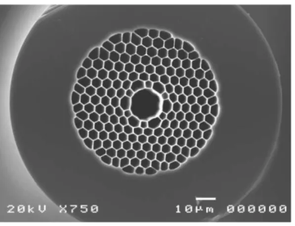
We have used a HC-PCF with a core formed by the omission of seven unit cells which presents no
sign of surface modes interactions within the bandgap. The photonic crystal cladding of this thin core
wall fiber has a pitch Λ = 6.7 m and an air filling fraction of ~ 96%, giving rise to a photonic
bandgap centered approximately at 1550 nm [22]. Furthermore, this fiber has a very low nonlinear
coefficient than conventional solid fibers,approximately three orders of magnitude less [23], due the
nonlinearity index of air is lower than silica or doped silica. This low nonlinearity combined with low
dispersion makes it ideal fiber to deliver and manipulate ultra-short pulses [24, 25] or optics sensorial
applications [26]. A scanning electron microscopy (SEM) image of fiber with thin core wall is shown
in Fig. 1.
Fig. 1. Hollow-core PCF.
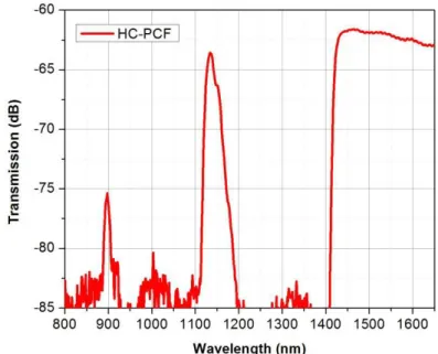
In order to measure the fiber PBGs, a white light source with tungsten filament, has been coupled to
the HC-PBGF and the output was analyzed using an Optical Spectrum Analyzer (OSA). Fig. 2 shows
its transmission spectrum for a fiber length of 200 m. One can observe there are three well-defined
transmission bands with low loss. In this work we concentrate our analysis in the range of 1535-1575
nm, which corresponds to C-Telecom band.
The minimum attenuation of HC-PCF is 15dB/km and remains below over 50 db/km more than 300
Fig. 2. Transmission Spectrum.
IV. EXPERIMENTAL SETUP
The experimental setup, shown in Fig. 3, was based on the following pieces of equipment: a
tunable External Cavity Laser (ECL), XYZ positioners, some objective lenses, tubes of different
diameters and a powermeter. The opticaloutput power from ECL source was 9 dBm.
Fig. 3. Experimental setup for measuring macrobending loss.
In order to measure the macrobending loss, we have twisted our fiber around some glass tubes and
observe the measured at the power meter before and after the bending. The tube diameters used for
this experiment were: 32, 20, 15, 12, 10, 7 and 4 mm. It was not possible to analyze the macrobending
loss for diameter of less than 4 mm because of the vey fiber air-filling fraction that usually leads to
break it. With the purpose of comparison, curves with the same diameter were made using a standard
SMF-28 fiber.
V. RESULTS
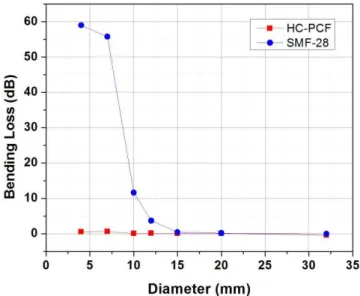
Initially, ECL wavelength was set to 1550 nm; the measurements of bending loss shown in Fig. 4.
For SMF-28 fiber, we observe there is a minimum curvature radius that allows light guidance into the
fiber core. When the critical radius is overcome, the guided mode escapes to the cladding in
guidance even for a very small bending radius, giving rise to extremely low macrobending loss.
Fig. 4. Measurmeents of macrobending losses.
HC-PCF has overcome the performance of SMF-28 for all bending diameters bellow 15 mm. For
instance, for a diameter of 12 mm, SMF-28 presents a bending loss of 3.7 dB, whereas the proposed
HC-PCF provides a loss of only 0.11 dB. Furthermore, it was a loss of only 0.58 dB for a bending
diameter of 4 mm, bending radius of 2 mm, whereas in SMF-28 loss reached up to 58.98 dB. A CCD
camera has also been used to optimize the fiber coupling and obtain near field image of hollow-core
fiber output at 1550 nm with minimum bending radius of 2 mm, as shown in Fig. 5. It is clear that the
light is entirely confined to PCF core.
Fig. 5. Near field at 1550 nm for 2 mm bendingradius.
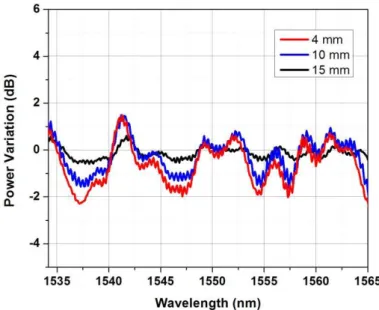
Finally, it was used an Amplified Spontaneous Emission (ASE) from an Erbium-Doped Fiber
Amplifier, as a broadband source to evaluate possible bandgap variations due to macrobends in
HC-PCF. These results are displayed in Fig. 6.The induced macrobends on the fiber can causes changes in
the photonic crystal. We observed as the bending diameter increase, insignificant shift appears on the
spectrum, since the guidance is slightly affected at certain wavelengths by only a few dBs in power.
Such power variations is more sensitive at the center bandgap edges, where the highly loses are
Fig. 6.Power variation for different bending diameters.
VI. CONCLUSIONS
According to ITU-T G.657 standard, developed by Study Group 15, approved and introduced in
December 2006 there are two categories in single-mode optical fiber design for access networks,
which are the G.657A and G.657B [11]. The G.657B pattern is the most strictness; so we used it to
evaluate the performance of the proposed fiber. In this standard, the minimum loss acceptable is 0.15
dB at 10 mm bending diameter at 1550 nm. Under these conditions, the proposed hollow-core fiber
showed a loss of only 0.09 dB. Furthermore, a bending loss of only 0.58 dB at 4 mm was reached and
for values more than 12 mm there were not significant losses.
As conclusion, the HC-PGBF can be applied for FTTH solutions since it overcoming the straight
requirements from ITU-T G.657B. Moreover, this fiber demonstrated power penalties below 3 dB
over 1535-1575 nm range even at strictness bends and showed that can be a solution for fusion effect
at MDUs. This fiber also can also be efficiently applied in tiny sensing devices with multiple radius of
curvature [10].
ACKNOWLEDGMENT
The authors would like to thanks Jonathan Knight from the University of Bath for providing the
fiber used in the experiments. Moreover, the authors also wish to acknowledge the financial support
from CAPES and FAPESP under CePOF and FOTONICOM contracts.
REFERENCES
[1] ArismarCerqueira S. Jr., “Recent progress and novel applications of photonic crystal fibers”, Rep. on Progress in Physics, vol. 73, no.
2, Jan. 2010.
[2] P. St. J. Russell, “Photonic crystal fibers,” Science, vol. 299, no. 5605, pp. 358–362, Jan. 2003.
[3] J. C. Knight , “Photonic crystal fibres,” Nature, vol.424, pp. 847–851, Aug. 2003.
[4] R. F. Cregan, B. J. Mangan, J. C. Knight, T. A. Birks, P. St. J. Russell, P. J. Roberts and D. C. Allan, “Single-Mode Photonic Band
Gap Guidance of Light in Air”, Science, vol. 285, pp. 1537-1539, Set. 1999.
[5] P. J. Roberts, F. Councy, H. Sabert, B. J. Mangan, D. P. Williams, L. Farr, M. W. Mason and A. Tomlinson, “Ultimate low loss of
[6] D. M.-Hernández, V. P. Minkovich, J. Villatoro, M. P. Kreuzer, and G. Badenes, “Photonic crystal fiber microtaper supporting two
selective higher-order modes with high sensitivity to gas molecules” Appl. Phys. Lett.93, Aug. 2008.
[7] D. G. Ouzounov, F. R. Ahmad, D. Müller, N.Venkataraman, M. T. Gallagher, M. G. Thomas, J.Silcox, K. W. Koch, and A. L. Gaeta,
“Generation of Megawatt Optical Solitons in Hollow-Core Photonic Band-Gap Fibers” Science vol. 301, no. 5640,pp. 1702-1704, Sep.
2003.
[8] F. Couny, F. Benabid, P. J. Roberts, P. S. Light, M. G. Raymer, “Generation and Photonic Guidance of Multi-Octave
Optical-Frequency Combs” Science vol. 318, no. 5853, pp. 1118 - 1121, Nov. 2007.
[9] J. Shephard, W. MacPherson, R. Maier, J. Jones, D. Hand, M. Mohebbi, A. George, P. Roberts, and J. Knight, “Single-mode mid IR
guidance in a hollow-core photonic crystal fiber” Optics Express, vol. 13, no. 18, pp. 7139-7144, Sep. 2005.
[10]Y.-J. Rao, M. Deng, T. Zhu, and H. Li, “In-Line Fabry-Perot Etalons Based on Hollow-Core Photonic Bandgap Fibers for
High-Temperature Applications”, J.Lightw. Tech., vol.17, no. 19, pp 4360-4365. Oct. 2009.
[11]ITU, ITU-T Recommendation G.657.
[12]H. A. Hmida, G. C. Cordner, A. Amer and F. F. Shalan, “FTTH Design and Deployment Guidelines for Civil Work, Fiber Distribution
and Numbering”, OFCNFOEC 2006, Mar. 5-10, 2006.
[13] R. E.Wagner, J. R. Igel, R. Whitman, M. D. Vaughn, A. B. Ruffin, andS. Bickham, “Fiber-based broadband-access deployment in the
UnitedStates,” J. Lightw. Technol., vol. 24, no. 12, pp. 4526-4540, Dec. 2006.
[14]D. Z. Chen, W. R. Belben, J. B. Gallup, C. Mazzali, P. Dainese, T. Rhyne, “Requirements for Bend Insensitive Fibers for Verizon’s
FiOS and FTTH applications”, OCFNFOEC 2008, San Diego, CA, Feb. 24-28, 2008.
[15]M.-J. Li, P. Tandon, D. C. Bookbinder, S. R. Bickham, M. A. McDermott, R. B. Desorcie, D. A. Nolan, J. J. Johnson, K. A. Lewis,
and J. J. Englebert, “Ultra-Low Bending Loss Single-Mode Fiber for FTTH”, J. Lightw. Tech., vol. 27, no. 3, pp 376-382, Feb. 2009.
[16]ITU, ITU-T Recommendation G.652.
[17]F. Wu et al., “A new G.652D, zero water peak fiber optimized for lowbend sensitivity in access networks,” in IWCS 2006, Providence,
RI,Nov. 12–15, 2006.
[18]K. Nakajima, K. Hogari, J. Zhou, K. Tajima, and I. Sankawa, “Hole-assistedfiber design for small bending and splice losses,” IEEE
Photon.Technol. Lett., vol. 15, no. 12, pp. 1737-1739, Dec. 2003.
[19] S. Matsuo, M. Ikeda, and K. Himeno, "Bend-insensitive and low-splice-loss optical fiber for indoor wiring in FTTH," in OFC 2004,
Los Angeles, CA, Feb. 22, 2004.
[20]L. Xiao, M.S. Demokan, W. Jin, Y. Wang and C.-L. Zhao, “Fusion Splicing Photonic Crystal Fibers and Conventional Single-Mode
Fibers: Microhole Collapse Effect”, J. Lightw. Tech., vol. 25, no. 11, pp 3563-3574, Nov. 2007
[21] P. S. André, A. M. Rocha, B. Neto, A. Martins, M. Facão, J. L. Pinto, A. L. J. Teixeira, R. N. Nogueira, M. J. Lima, G. Incerti, D.
Forinand G. T. Beleffi, “OpticalFiberBendingLimits for OpticalFiberInfraestrutures”, IEEE AFRICON 2009, pp. 1-3, Sept. 23-25,
2009.
[22]R. Amezcua-Correa, F. Gérôme, S. G. Leon-Saval, N.G.R. Broderick, T. A. Birks and J. C. Knight, “Control of surface modes in low
loss hollow-core photonic bandgap fibers”, Opt. Express, vol. 16, no. 2, pp. 1142-1149, Jan. 2008.
[23]M. Welch, R. Amezcua-Correa, F.Gérôme, S. Renshaw, and J. Knight. “Tailoring the Nonlinear Response of Hollow-core Photonic
BandgapFibres”, WSOF 2008, São Pedro, São SP, Brazil, Aug. 20-22, 2009.
[24]J. Shephard, J. Jones, D. Hand, G. Bouwmans, J. C. Knight, P. Russell, and B. Mangan, “High energy nanosencond laser pulses
delivered single-mode trough hollow-core PBG fibers.”, Opt. Express, vol. 12 , no. 4, pp. 717-723, Feb. 2004.
[25]F. Luan, J. Knight, P. Russell, S. Campbell, D. Xiao, D. Reid, B. Mangan, D. Williams, and P. Roberts, “Femtosecond soliton pulse
delivery at 800 nm wavelength in hollow-core photonic bandgap fiber” Opt. Express, vol. 12, no. 5, pp. 835-840, Feb. 2004.
[26] S. H. Aref, R. Amezcua-Correa, J. P. Carvalho, O. Frazão, P. Caldas, J. L. Santos, F. M. Araújo, H. Latifi, F. Farahi, L. A. Ferreira,
and J. C. Knight, “Modal interferimeter based on hollow-core photonic crystal fiber for strain and temperature measurement”, Opt. Express, vol. 17, no. 21, pp. 18669-18675, Oct. 2009.