Antimicrobial Biomaterials for use as Dialysis
Catheters
Inês Silva Borges
Integrated Master in Bioengineering Branch of Molecular Biotechnology
Supervisor: Dr Inês Gonçalves (i3S)
Co-supervisor: Dr Fernão Magalhães (LEPABE-FEUP)
The work described in this thesis was conducted at:
I3S/INEB - Instituto de Investigação e Inovação em Saúde; Universidade do Porto
LEPABE/FEUP - Laboratório de Engenharia de Processos, Ambiente, Biotecnologia e Energia; Universidade do Porto
The work described in this thesis was financially supported by:
Project POCI-01-0145-FEDER-007274 (Institute for Research and Innovation in Health Sciences); Project POCI-01-0145-FEDER-006939 - Laboratory for Process Engineering, Environment, Biotechnology and Energy – LEPABE and NORTE‐01‐0145‐FEDER‐000005 – LEPABE-2-ECO-INNOVATION, funded by FEDER funds through COMPETE2020 - Programa Operacional Competitividade e Internacionalização (POCI) and Programa Operacional Regional do Norte (NORTE2020), and by national funds through FCT - Fundação para a Ciência e a Tecnologia; and Project PTDC/CTM-Bio/4033/2014 (NewCat - New biomaterials to prevent infection associated with dialysis catheters), funded by FEDER funds through COMPETE2020 - Programa Operacional Competitividade e Internacionalização (POCI) – and by national funds through FCT - Fundação para a Ciência e a Tecnologia.
Se podes olhar, vê. Se podes ver, repara.
i
Acknowledgments
Acabam assim 5 anos de muitas aventuras, muitas aprendizagens, muitas descobertas, muitos encontros e desencontros. Enfim, um período cheio de muitos, de demasiados e de q.bs. Um período muito rico. Rico essencialmente de pessoas. E é a essas pessoas que tenho que agradecer. Obrigada principalmente aos “amores que ficam para a vida”, sem vocês isto não tinha piada nenhuma. São essencialmente vocês que ficam, e ficam para sempre.
Tenho que agradecer aos meus orientadores, Dr Inês Gonçalves e Dr Fernão Magalhães, a quem devo este trabalho e todo o apoio e disponibilidade demonstrados. Obrigada pela oportunidade. Em especial à minha orientadora, à fantástica Inês Gonçalves. Se eu já a admirava antes, esse sentimento só se multiplicou nestes últimos meses.
Um grande obrigado ao Artur Pinto que me ensinou tudo. À Patrícia Henriques, à Diana Paiva que contribuíram diretamente e me ajudaram imenso.
Aos meninos do E-146 que tornaram muito mais divertido trabalhar naquele laboratório, obrigada pelas risadas e boa disposição.
Um agradecimento especial a toda a equipa do nBTT- Nanobiomaterials to control infection and thrombus formation. Obrigada Fabíola, Cláudia, Catarina, Maura por se mostrarem sempre disponíveis e por terem de aturar as minhas dúvidas. Aos coleguinhas mais novos e com quem partilhei tantas frustrações, tantas risadas, foi muito bom termo-nos uns aos outros. Micaela, Diana e Luís, muito obrigada! Obrigada especialmente na ajuda com as experiências megalómanas. Desejo-vos o melhor no vosso futuro, vai correr tudo bem! A verdade é que tudo se torna mais fácil quando estamos rodeados pelas pessoas certas e eu tive imensa sorte, porque conheci e trabalhei com pessoas espetaculares.
Obrigada às minhas karatecas por também terem de levar com as minhas frustrações e me ajudarem a livrar de energias negativas e estar sempre no meu melhor.
Finalmente, um grande obrigado à minha família. Só sou o que sou hoje graças ao vosso apoio, compreensão e acompanhamento. Pai, mãe e Miguel, vocês são essenciais e imprescindíveis para eu dar o melhor de mim e procurar ultrapassar-me a cada obstáculo.
iii
Abstract
End-stage renal disease is a worldwide public health problem with an increasing incidence and prevalence. The population affected needs to perform kidney transplant or, in most of the cases, dialysis for the rest of their lives as a process to remove waste and excess water from the blood. Dialysis catheters are an immediate and effective lifeline for dialysis patients however they are associated with a greater risk of infection and hospitalization. Dialysis catheter-related infections are a serious public health issue that can result in endocarditis or peritonitis, which can lead to sepsis and death.
So far, the existing strategies to convey antibacterial properties to catheter materials are not fully effective or present significant disadvantages. Therefore and since the number of dialyzed patients and bacteria resistance to antibiotics are increasing, catheter-related infections will became an even more alarming problem in the near future. As such, the design of a new biomaterial for the development of antimicrobial catheters is a striking need.
Since graphene discovery, graphene-based materials (GBMs) have excited researchers from several different areas. Biocompatibility and antimicrobial properties are particular goals when it comes to the biomedical and biological applications of GBMs and materials containing GBMs.
This work focused on the antibacterial potential of GBMs, in particular graphene nanoplatelets, for the development of a material for catheter production to prevent the infections that occur due to bacteria adhesion and growth on the catheter surface. Polyurethane (PU) is the polymer most commonly used for catheter manufacture and the modification of its surface was therefore studied on the course of this work. Specifically, a commercially available form of graphene nanoplatelets grade M (GNP-M) was investigated for the first time to confer antibacterial properties to PU. The effect of nanoplatelets size and oxidation was also studied, using GNP with two different sizes: GNP-M5 and GNP-M15, which have 5 µm and 15 µm average lateral size, respectively. For biomaterials development, two different strategies were explored: i) polyurethane composites with GNP as nanofillers and ii) GNP-containing coatings on PU. The antibacterial properties of the produced materials, namely non-oxidized and oxidized GNPs powders, PU/GNP composites and PU/GNP coatings, were tested towards Staphylococcus epidermidis bacteria.
Oxidation of GNP was successfully performed and antimicrobial studies showed that oxidized GNPs have stronger antibacterial activity than non-oxidized GNPs and that smaller particle size improves the antibacterial properties. PU/GNP composites produced by melt-blending showed a good dispersion of GNPs in the polyurethane matrix but no significant modification of the surface, with few GNPs exposed in a planar orientation and mostly covered with polymer. Antibacterial assessment confirmed that the GNPs present at the surface of the composites were not sufficient to effectively contact bacteria and no effects were detected on bacteria attachment, metabolic activity or viability. Finally, GNP-containing coatings were produced by dip coating and different GNP concentrations and PU:GNP ratios were tested. It was demonstrated that good dispersions and solvent evaporation are critical factors to fabricate uniform and homogeneous coatings. The PU/GNP-M and PU/GNP-Mox coatings produced showed increased GNPs exposure at the surface comparing with the melt-blending composites. Oxidized GNP induced higher antibacterial effect towards S. epidermidis than
iv
non-oxidized forms, either through anti-adhesive or bactericidal activity, depending on the GNP concentration used.
Overall, this work demonstrates the potential of using GBMs as nanomaterials to confer antibacterial properties to PU, and hence as a promising strategy to produce a biomaterial for catheter production with reduced risk of infection.
v
Table of contents
ACKNOWLEDGMENTS ... I ABSTRACT ... III TABLE OF CONTENTS ... V FIGURE LIST ... VII TABLE LIST ... XI ABBREVIATIONS AND SYMBOLS ... XII
CHAPTER I: MOTIVATION AND AIM ... 1
1. MOTIVATION AND AIM ... 1
2. STRUCTURE OF THE DISSERTATION ... 2
CHAPTER II: LITERATURE REVIEW ... 3
1. DIALYSIS CATHETERS: AN OVERVIEW ... 3
2. CATHETER-RELATED INFECTION ... 4
2.1 Staphylococcus epidermidis ... 5
3. HEMODIALYSIS CATHETERS: MATERIALS AND MANUFACTURING ... 6
4. GRAPHENE-BASED MATERIALS (GBMS) ... 7
5. ANTIMICROBIAL ACTIVITY OF GBMS ... 9
5.1. Non-functionalized GBMs ... 9
5.2. Functionalized GBMs ... 19
6. COMPOSITES CONTAINING GBMS ... 24
6.1. PU/GBMs Composites ... 25
7. ANTIMICROBIAL ACTIVITY OF COMPOSITES CONTAINING GBMS ... 26
7.1. PU/GBMs Composites ... 27
CHAPTER III: MATERIALS AND METHODS ... 31
1. MATERIALS PRODUCTION ... 31
1.1. Graphene Nanoplatelets (GNPs) Powders ... 31
1.1.1. Graphene Nanoplatelets (GNPs) ... 31
1.1.2. GNPs Oxidation ... 31
1.1.3. GNPox Dispersions Stability ... 32
1.2. GNPs-containing Materials ... 32
1.2.1. Polyurethane (PU) ... 32
1.2.2. PU/GNP Composites by Melt-Blending ... 32
1.3. PU/GNP Coatings by Dip Coating ... 33
1.3.1. Glass coverslip as substrate... 33
1.3.2. PU film as substrate ... 34
2. MATERIALS CHARACTERIZATION ... 35
2.1. X-ray photoelectron spectroscopy (XPS) ... 35
2.2. Scanning electron microscopy (SEM) ... 36
2.3. Water Contact Angle ... 36
2.4. Stereomicroscopy ... 36
2.5. Thermogravimetric (TG) analysis ... 37
2.6. Rubbing test ... 37
3. ANTIBACTERIAL PROPERTIES ... 37
3.1. Bacteria Strains and Growth Conditions ... 37
vi
3.3. Antibacterial assessment ... 38
3.3.1. Planktonic Bacteria ... 39
3.3.2. Adherent or Sessile Bacteria ... 40
CHAPTER IV: RESULTS AND DISCUSSION ... 43
1. GNP-M DRY POWDERS AND CHEMICAL OXIDATION ... 43
2. ANTIBACTERIAL ACTIVITY OF GNP AND GNPOX DISPERSIONS ... 45
3. PU/GNPCOMPOSITES ... 47
3.1. Antibacterial Properties of PU/GNP composites ... 51
4. PU/GNPCOATINGS ... 54
4.1. PU/GNP-M coatings on glass coverslips ... 54
4.2. PU/GNP-M coatings on PU films ... 57
4.3. Antibacterial Properties of PU/GNP coatings ... 64
CHAPTER V: CONCLUSION AND FUTURE WORK ... 71
1. CONCLUSION ... 71
2. FUTURE WORK ... 72
REFERENCES ... 73
vii
Figure List
Figure 1. The three types of vascular access: arteriovenous fistula (A), arteriovenous graft (B)
and venous catheter (C).The arrows illustrate the direction of the blood flow. In the first case (A), needles and tubes are inserted in the AV fistula, while in the second case (B) they are inserted in the tube that connects the vein with the artery. Adapted from Diseases, 20148. ... 3
Figure 2. Structure of an hemodialysis catheter6. ... 4
Figure 3. Staphylococcus clusters5. ... 5
Figure 4. Synthesis of polyether-based polyurethanes Pelletane® and Tecothane®. Adapted
from Ma et al.7. ... 7
Figure 5. Tecothane® thermoplastic polyurethane (TPU) pellets. ... 7 Figure 6. SEM images of E. coli after incubation with saline solution without GO (a), and with
GO dispersion (40 μg/mL) for 2 h (b). Adapted from Liu et al.9 ... 17
Figure 7. Differences between the structures of gram-positive and gram-negative bacteria. .. 17 Figure 8.The melt compounder (A) and injection moulder (B) used to produce PU/GNP-M
composites by melt blending. ... 33
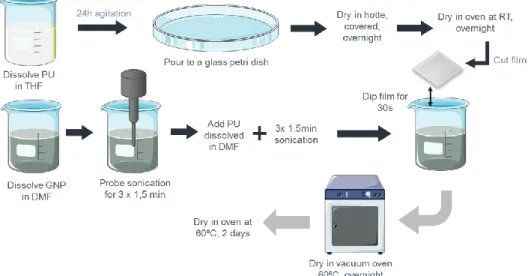
Figure 9. Schematic of glass coverslips dip-coating into PU/GNP solution. The marks the time points where thermogravimetric analysis (TGA) was performed. ... 33
Figure 10. Schematic of PU films dip-coating into PU/GNP solution. ... 34 Figure 11. Schematic representation of the essential steps of the antibacterial assessment. (A)
Inoculation of the samples and placement of cover film; (B) Bacterial suspension held in intimate contact with the sample’s surface by the polypropylene (PP) film for 24 h at 37°C. ; (C) Detachment of the PP film and further analysis of the bacteria present in the supernatant and bacteria adherent to the surface. ... 39
Figure 12. SEM images of dry powders of GNP-M5, GNP-M15 and their oxidised forms GNP-M5
oxidised by the MHM and by the Marcano’s method, and GNP-M15 oxidised by the MHM. Sharped and folded edges are indicated by red and yellow arrows, respectively. Each row corresponds to magnifications of each material at 1 000 ×, 20 000 × and 50 000 × (scale bar = 100 µm, 5 µm and 2 µm, respectively). ... 43
Figure 13. XPS spectra fitting for the core level C 1s of GNP-M5 (A), GNP-M15 (B) and GNP-M5
oxidised by the Modified Hummers Method (C) and Marcano’s method (D). Table shows content of C 1s chemical groups resulting from XPS spectra fitting (E). ... 45
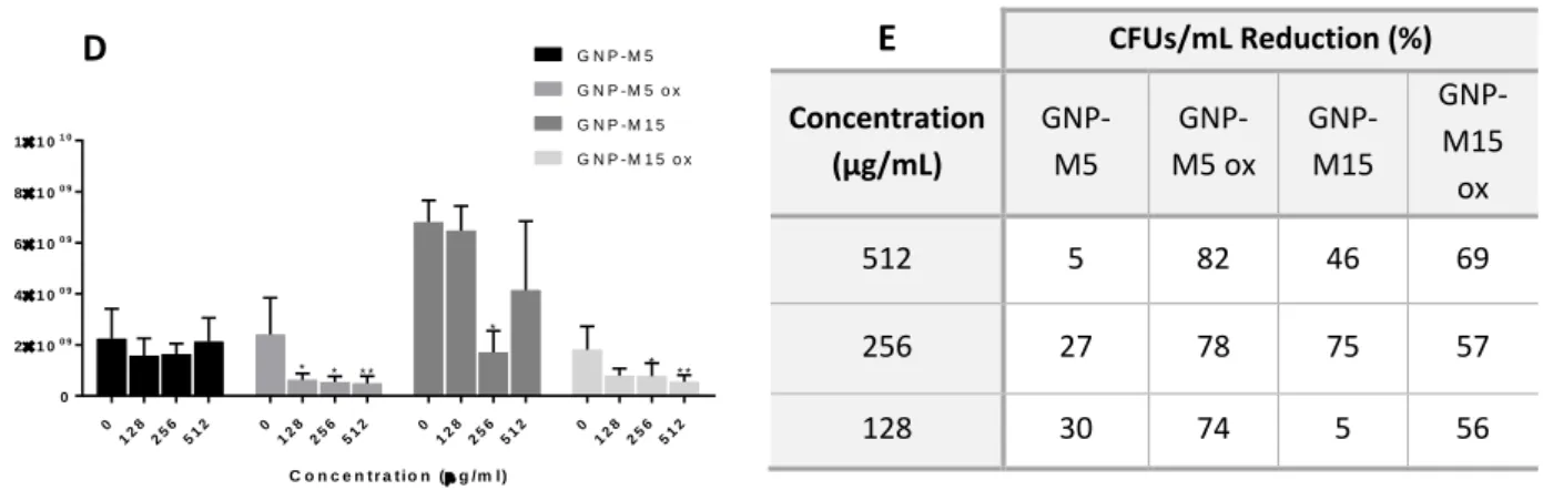
Figure 14. S.epidermidis metabolic activity cultured for 24h with GNP-M5 and GNP-M5 ox (A),
GNP-M15 and GNP-M15 ox (B) aqueous dispersions. Metabolic activity reduction calculated as percentage of the control (bacteria without GNPs) (C). Bacteria viability for all dispersions (D). CFU reduction calculated as percentage of the control of the bacteria grown without GBMs (E). For the metabolic activity data and CFUs/mL the statistical tests performed were the one way ANOVA and Kruskal Wallis (P < 0.05), respectively. *, *****, and **** statistically significant different from control (0 µg/mL) (p ≤ 0.05, p≤0.01, p≤0.001 and p≤0.0001). ... 47
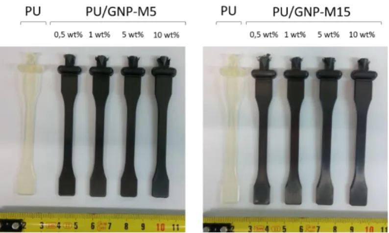
Figure 15. Digital pictures of the PU/GNP composites produced by melt-blending. ... 48
viii
Figure 16. PU and PU/GNP-M5 composite SEM images at different magnifications. Lower
magnification (1 000×) pictures were taken to see both the surface and the transversal fracture (Surface + Matrix) while higher magnification (10 000×) pictures were taken to the transversal fracture to analyse the composite matrix (Matrix) and to the composites’ surface (Surface). Additional pictures with higher magnifications were taken when GNP was found exposed at the surface of PU/GNP-M5 1 wt% (I-1, 40 000×)) and PU/GNP-M5 10wt% (1, 40 000×, and O-2, 60 000×). Red arrows indicate the presence of GNP. (Scale bar = 100 µm, 10 µm, 2 µm and 1µm for 1 000×, 10 000×, 40 000× and 60 000× magnifications, respectively). ... 48
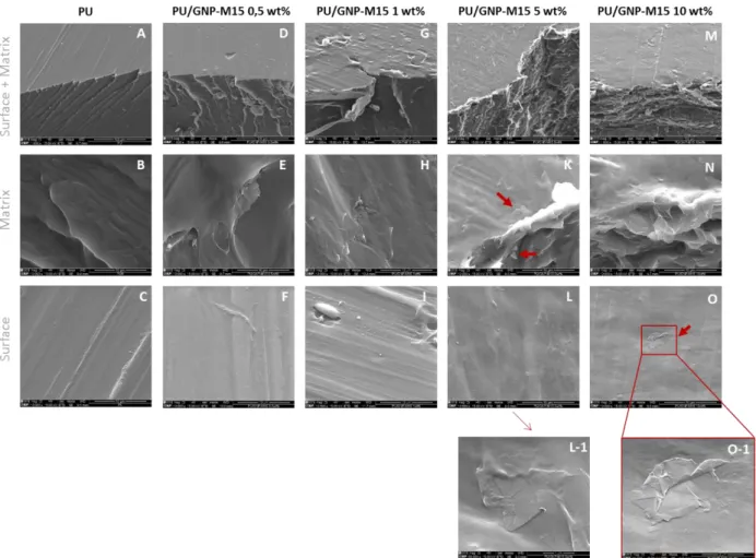
Figure 17. PU/GNP-M15 composite SEM images at different magnifications. Lower
magnification (1 000×) images were taken to see both the surface and the transversal fracture (Surface + Matrix) while higher magnification (10 000×) images of the transversal fracture show the composite matrix (Matrix) and the composites’ surface (Surface). Additional images with higher magnifications were taken when GNP was found exposed at the surface (L-1, 60 000× and O-1, 40 000×). Red arrows indicate the presence of GNP. (Scale bar = 100 µm, 10 µm, 2 µm and 1µm for 1 000×, 10 000×, 40 000× and 60 000× magnifications, respectively). .. 49
Figure 18. Water contact angle measurement for PU (control), PU/GNP-M5 and PU/GNP-M15
composites obtained by melt-blending. Statistic test performed was Kruskal Wallis and * indicates statistically significant different from control (PU) (p ≤ 0.05). ... 50
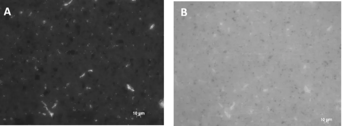
Figure 19. Representative fluorescence pictures of PU/GNP-M5 0,5 wt% stained with
propidium iodide (PI) (A) and Syto9 (B). Magnification of 40×. ... 51
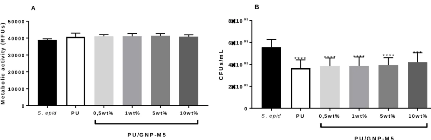
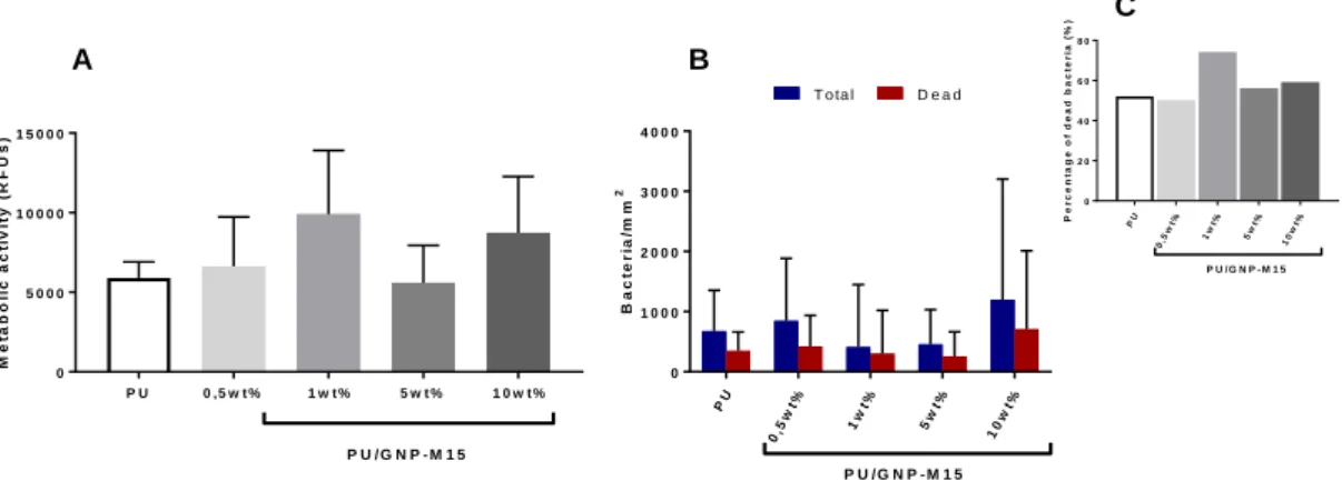
Figure 20. Planktonic Bacteria. Metabolic activity (A) and cultivable bacteria counting (B) of
planktonic S.epidermidis cultured with PU/GNP-M5 composites. Statistical analysis of CFUs/mL performed with one-way ANOVA and Metabolic Activity with Kruskal Wallis tests. Statistical difference (****) was only observed comparing with the CFUs/mL value of the control of S.epidermidis cultured on PP film (p ≤ 0.0001) ... 52
Figure 21. Adherent Bacteria. Metabolic activity of adhered bacteria (A) and comparison
between the total and the dead adhered bacteria (B) on PU/GNP-M5 composites produced by melt-blending. Figure C represents the percentage of dead bacteria. No significant differences were detected. ... 53
Figure 22. Planktonic Bacteria. Metabolic activity (A) and cultivable bacteria counting (B) of
planktonic S.epidermidis cultured with PU/GNP-M15 composite. Statistical analysis of CFUs/mL performed with one-way ANOVA and Metabolic Activity with Kruskal Wallis tests and differences between samples are indicated with * (p ≤ 0.05), ** (p≤0.01) and *** (p≤0.001). 53
Figure 23. Adherent Bacteria. Metabolic activity of adhered bacteria (A) and comparison
between the total and the dead adhered bacteria (B) on PU/GNP-M15 composites produced by melt-blending. Figure C represents the percentage of dead bacteria. No statistically significant differences were detected. ... 53
Figure 24. Pictures of the PU/GNP composite coatings on glass coverslips (scale bar represents
3 mm for all images). ... 55
Figure 25. Thermogravimetry analysis of PU/GNP coatings obtained on glass coverslips before
and after vacuum drying. ... 55
Figure 26. SEM images of PU and PU/GNP coatings on glass coverslips. In the lower
magnification (1 000×) images the interface between the coating and the glass coverslip is visible (A, D, G, J and M). Higher magnification (10 000×) pictures were taken to the coatings’
ix matrix (B, E, H, K and N) and surface (C, F, I, L and O). Yellow arrows indicate the presence of GNP and blue squares indicate observed bubbles at the surface. (Scale bar = 100 µm and 10 µm for 1 000×, and 10 000× magnifications, respectively). ... 56
Figure 27. Energy-dispersive X-ray spectroscopy (EDS) was performed at different areas of the
PU/GNP-M5 and PU/GNP-M5 ox coatings’ surface on glass. Blue arrow indicates the presence of sulphur (S). Pictures B, C and D represent the EDS spectrums of zones Z1, Z2 and Z3 of the PU/GNP-M5 coating (A), respectively. While pictures F and G represent the EDS spectrums of zones Z1 and Z2 of the PU/GNP-M5ox coating (B), respectively. ... 57
Figure 28. SEM images of PU/GNP coatings applied on PU obtained from extrusion-injection
molding method. In the lower magnification (1 000×) pictures the interface between the coating and the PU is visible (A, D, G and K). Higher magnification (10 000×) pictures were taken to see in detail the coatings’ matrix (B, E, H and L) and surface (C, F, I, J and M). Pictures I and J are from the same PU/GNP-M15 coating but in zones that present distinct topography. Yellow arrows indicate the presence of GNP. (Scale bar = 100 µm and 10 µm for 1 000× and 10 000× magnifications, respectively). ... 58
Figure 29. 2 wt%, 5 wt% and 10 wt% (left to right) GNP dispersions after 2h settling: GNP-M5 in
THF (A) and DMF (B); GNP-M5 ox in THF (C) and DMF (D); GNP-M15 in THF (E) and DMF (F); GNP-M15 ox in THF (G) and DMF(H). ... 59
Figure 30. 2 wt%, 5 wt% and 10 wt% (left to right) GNP dispersions after 1 day settling:
GNP-M5 in THF (A) and DMF (B); GNP-GNP-M5 ox in THF (C) and DMF (D); GNP-M15 in THF (E) and DMF (F); GNP-M15 ox in THF (G) and DMF(H). ... 59
Figure 31. Images of the different samples obtained: PU film produced by casting and PU
coating on PU film (control), PU/GNP-M5 (A) and PU/GNP-M5 ox coatings (B) on PU film ... 59
Figure 32. SEM images of the PU film produced by casting, PU coating on PU film (control) and
PU/GNP-M5 coatings on PU film at different GNP concentrations and PU:GNP ratios tested. Pictures at 1 000× (picture 1), 10 000× (picture 2) and 25 000× (picture 3) magnifications were taken. Blue arrow indicates GNP partially covered with polymer and yellow arrow pints to GNP transversely oriented. (Scale bar = 100 µm, 10 µm and 4 µm for 1 000×, 10 000× and 25 000× magnifications, respectively). ... 61
Figure 33. SEM images of the PU film produced by casting, PU coating on PU film (control) and
PU/GNP-M5ox coatings on PU film at different GNP concentrations and PU:GNP ratios tested. Pictures at 1 000× (picture 1), 10 000× (picture 2) and 25 000× (picture 3) magnifications were taken. (Scale bar = 100 µm, 10 µm and 4 µm for 1 000×, 10 000× and 25 000× magnifications, respectively). ... 62
Figure 34. Water contact angle measurement for PU film obtained by casting, PU coating,
PU/GNP-M5 (A) and PU/GNP-M5 ox (B) coatings applied on PU casting film. Statistic test performed was Kruskal Wallis and statistically significant differences are indicated with * (p ≤ 0.05), ** (p≤0.01), *** (p≤0.001) and **** (p≤0.0001). ... 63
Figure 35. Circular samples (14 mm diameter) obtained by cutting the dip-coated squares with
a puncher. A- PU coating and PU/GNP-M5 1mg/mL 1:2, 0.5 mg/mL 1:1, 0.5 mg/mL 1:2, 0.5 mg/mL 1:4 and 0.25 mg/mL 1:2 coatings from left to right. B- PU coating and PU/GNP-M5 ox 1mg/mL 1:2, 0.5 mg/mL 1:1, 0.5 mg/mL 1:2, 0.5 mg/mL 1:4, 0.25 mg/mL 1:1 and 0.25 mg/mL 1:2 coatings from left to right. ... 64
x
Figure 36. Planktonic Bacteria. Metabolic activity and cultivable bacteria counting of
planktonic S.epidermidis cultured on PU/GNP-M5 coatings on PU. Statistical analysis of CFUs/mL performed with one-way ANOVA and Metabolic Activity with Kruskal Wallis tests and differences are indicated with * (p ≤ 0.05), ** (p≤0.01) and *** (p≤0.001). ... 65
Figure 37. Adherent Bacteria. Metabolic activity of adhered bacteria (A) and comparison
between the total and the dead adhered bacteria (B) on PU/GNP-M5 coatings on PU. Figure C, is a zoomed Figure B and excluding the controls PP film and TC coverslips to better compare the PU/GNP-M5 coatings with neat PU coating. The percentage of dead bacteria for each sample is described at D. Statistical analysis performed with Kruskal Wallis test and differences are indicated with * (p ≤ 0.05), ** (p≤0.01), *** (p≤0.001) and **** (p≤0.0001). ... 65
Figure 38. Planktonic Bacteria. Metabolic activity and cultivable bacteria counting of
planktonic S.epidermidis cultured on PU/GNP-M5ox coatings on PU. Statistical analysis of CFUs/mL performed with one-way ANOVA and Metabolic Activity with Kruskal Wallis tests. Statistically significant differences are indicated with * (p ≤ 0.05) and ** (p≤0.01). ... 67
Figure 39. Adherent Bacteria. Metabolic activity of adhered bacteria (A) and comparison
between the total and the dead adhered bacteria (B) on PU/GNP-M5ox coatings on PU. Figure C, is a zoomed Figure B and excluding the controls PP film and TC coverslips to better compare the PU/GNP-M5 coatings with neat PU coating. The percentage of dead bacteria for each sample is described at D. Statistical analysis performed with Kruskal Wallis test and differences are indicated with * (p ≤ 0.05), ** (p≤0.01), *** (p≤0.001) and **** (p≤0.0001). ... 68
xi
Table List
Table 1 - Effects of GBMs aqueous dispersions on bacteria. ... 12
Table 2 - Effects of GBMs films on bacteria. ... 15
Table 3 - Effects of GBMs composites on bacteria. ... 28
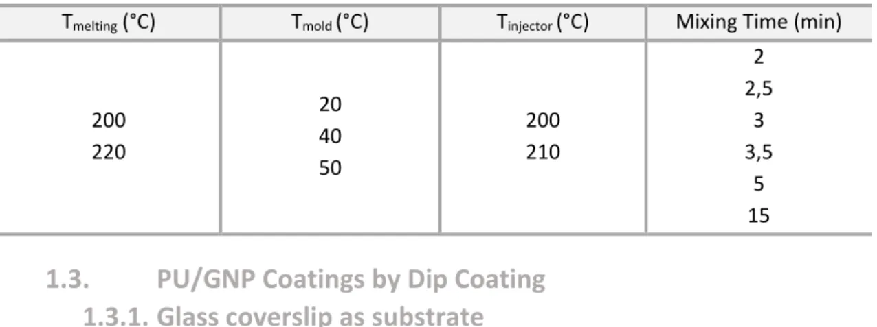
Table 4 - Different parameters tested for melt compounding optimization. ... 33
Table 5 – The different GNP concentrations and PU:GNP ratios tested to produce coatings on PU films. ... 35
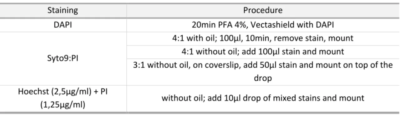
Table 6 – Different conditions and stains tested for adherent bacteria viability assessment. .. 40
Table 7 - Surface atomic composition (%) of the GNP-M5, GNP-M15, GNP-M5 oxidised by the MHM and GNP-M5 oxidised by the Marcano’s method calculated from high-resolution XPS spectra. ... 45
xii
Abbreviations and Symbols
AVF - arteriovenous fistula AVG - arteriovenous graft BB - brilliant blue
BP - benzylpenicillin
BSA - bovine serum albumin CD - β-cyclodextrin
CF - carbon foam
CFUs - colony-forming units CRB - catheter-related bacteremia CS - chitosan
CVD - chemical vapor deposition DI - deionized water
DMF - dimethylformamide EDS - energy-dispersive X-ray
spectroscopy
FGO - functionalized GO
FGt - functionalized few-layered graphite FLG - few-layer graphene
G - graphene
GBMs - graphene based materials GNPox - oxidized graphene
nanoplatelets GNPs - graphene nanoplatelets GNs - graphene nanosheets GO - graphene oxide GSH - glutathione Gt - graphite HD - hemodialysis
IONPs - iron oxide nanoparticles IPA - isopropanol
LB - Langmuir–Blodgett MBC - Minimal Bactericidal
Concentration
MDG - methanol derived graphene MHM - modified Hummers method MIC - Minimal Inhibitory Concentration NLf - native lactoferrin NPs - nanoparticles NRC - nanorod composite NWs - nanowires PBS - phosphate-buffered saline PD - peritoneal dialysis
PDDA - poly (diallyldimethylammonium
chloride)
PE - poly(ethylene) PEG - polyethylene glycol PEI - polyethyleneimine
PET - polyethylene terephthalate PHGC - polyhexamethylene guanidine
hydrochloride
PI - propidium iodide PLA - poly (lactic acid) PLL - poly-L-lysine PNIPAM - poly(N-isopropylacrylamide) PP - polypropylene PPC - poly(propylene carbonate) PS - polystyrene PU - polyurethane PVA - poly(vinyl alcohol) PVDF - polyvinylidene fluoride PVK - polyvinyl-N-carbazole PVP - polyvinyl pyrrolidone RFUs - relative fluorescence units rGO - reduced graphene oxide ROS - reactive oxygen species SEM - Scanning electron microscopy SOD - superoxide dismutase
TCC - tunneled cuffed catheter
TCF - transparent conductive film (TCF) TGA - Thermogravimetric analysis THF - tetrahydrofuran
TSA - Trypticase Soy Agar TSB - Trypticase Soy Broth
TTP - tetradecyl triphenyl phosphonium
bromide
TWEEN - polyoxyethylene sorbitan
laurate
XPS - X-ray photoelectron spectroscopy
1
CHAPTER I:
Motivation and Aim
1. Motivation and Aim
Hemodialysis (HD) represents the most widely adopted therapy for patients with end-stage kidney disease. However, hemodialysis patients suffer from higher rates of morbidity and mortality, particularly due to vascular access-related problems. The challenge for the dialysis catheters is to find strategies to face its essential problems, involving infection and thrombosis. This has been subject of extensive research and developments have been made but research community has not achieved the so desirable goal, yet. Several strategies are currently being adopted but the results are still far for us to say that a solution has been created.
Meanwhile, since its recently discovery in 2004, graphene has changed the way we look to materials and has been conquering numerous fields. Is has blown away scientist with its outstanding properties. From batteries to solar panels, from clothes to sensors, from new composite materials to DNA transporters, from drug delivery to antimicrobial surfaces, everything can be improved with the use of graphene. Is seems that it can lead us to where we dare to go and to what our imagination makes us dream about. The interaction between graphene, or more generally graphene-based materials (GBMs), and biological systems is being intensively studied to give insights to the effects of GBMs on bacteria, mammalian cells, animals, and plants. In 2010 the antibacterial properties of GBMs were explored for the first time and since then a growing number of reports have described GBMs as antimicrobial nanomaterials. Several factors affect their activity such as the materials’ concentration, physical and chemical properties, and there is still a lot of controversy on the mechanisms of action. As materials with low mammalian cell cytotoxicity, increased antimicrobial properties and low cost caused by the cheap raw material, GBMs may become an ideal material in biomedical applications, namely biomedical devices and implants.
GBMs have been thought as a straightforward and economic approach to confer bactericidal properties to the most commonly used dialysis catheters. Thereby, incorporation of GBMs on the polymer used for catheter construction can improve the antimicrobial properties of dialysis catheters and consequently, GBMs may prevent catheter-associated infections. This was the purpose of this investigation and the motivation to access whether GBMs really represent a new revolution in the antimicrobial materials field as it has been verified in so many and distinct areas.
The objectives of this study were to prepare polymer surfaces containing GBMs and evaluate their antibacterial properties. The polymer used was polyurethane, since it is the material most commonly used for catheter production, and the GBMs used were commercial graphene nanoplatelets (GNPs). The effect of nanoplatelets size and oxidation was also studied, using GNP with two different sizes: GNP-M5 and GNP-M15. GNPs dispersions were also evaluated in terms of antibacterial properties. As it was known from the start this was not a straightforward study. Several difficulties were found and had to be overcome, and different strategies were assessed to reach a solution that had the potential to effectively work as an antibacterial material for catheter development.
2
2. Structure of the Dissertation
Chapter II – Literature Review aims to contextualize the problem assessed, including social and economic problems related to hemodialysis, as well as a more detailed review on catheter development, materials and manufacturing. There is also information on catheter-related infection and the microorganisms more associated to this health problem. The chapter ends with an extensive review on the state of art on graphene-based materials (GBMs) directed to their antimicrobial application and studies with bacteria.
In Chapter III - Materials and Methods the materials used and the experimental procedures are described in detail. It includes production, characterization techniques and biologic testing of the different materials produced. Starting from GNPs oxidation and antibacterial assessment of the powders aqueous dispersions. Followed by the two different approaches conducted for polymer modification: first the production of PU/GNP composites by melt-blending, in which GNPs are physically embedded in a PU matrix, and secondly the application of a GNP containing coating onto PU surfaces by dip-coating. In particular it was known that the orientation and exposure of the nanosheets was an important aspect on surfaces, being an essential factor for the bacterial toxicity of GBMs. Thereby, the material production methods were evaluated to optimize the exposure of GNPs on the polyurethane surface.
Results obtained and their consecutive discussion can be found in Chapter IV – Results and Discussion. This chapter is divided by the different materials produced: powders, composites and coatings. And in each section, the results from the characterization techniques and the antibacterial activity assessments performed for each type of material are described and discussed.
Finally, in the last chapter, Chapter V, the conclusions taken from this work are described and future work is also discussed.
3
CHAPTER II:
Literature Review
1. Dialysis Catheters: an Overview
Chronic kidney disease is a worldwide public health problem with an increasing incidence and prevalence, poor outcomes, and high cost 10. The number of patients with end-stage renal
disease is growing worldwide and the mortality of this patients is 10-20 times higher than that in the general population 11. Renal replacement therapy is essential for maintenance of life for
those with end-stage renal disease, which can be performed in two different modalities: dialysis and kidney transplantation 12.
Dialysis is the process to remove waste and excess water from the blood. There are two types of dialysis: hemodialysis (HD) and peritoneal dialysis (PD). While HD filters the blood outside the body allowing it to flow through a dialyzer, PD uses the lining or peritoneum of the abdominal cavity to filter blood inside the body through a draining process 13. The most
common is hemodialysis, but peritoneal dialysis is also performed and regarded as very promising since patients can benefit from the treatment at home without the need to travel to a healthcare center14. Catheters are soft tubes used in both types of dialysis6. As such, dialysis
catheters are an immediate and effective lifeline for dialysis patients and their use is steadily increasing. In HD, the site from where the blood is removed and returned is called the vascular access. HD differs in the type of vascular access which include the arteriovenous (AV) fistula (AVF, a connection between an artery and a vein) and the AV graft (AVG, a looped plastic tube that connects an artery to a vein) both more appropriate for long-term use; and the central venous catheter, which can be either temporary or a permanent tunneled catheter (Figure
1)15. The type of vascular access seems to have a significant influence on survival and studies
Figure 1. The three types of vascular access: arteriovenous fistula (A), arteriovenous graft (B) and venous catheter
(C).The arrows illustrate the direction of the blood flow. In the first case (A), needles and tubes are inserted in the AV fistula, while in the second case (B) they are inserted in the tube that connects the vein with the artery. Adapted from Diseases, 20148.
4
report AVF having the highest long-term patency and the lowest infection and complication rates 16; 17; 18.
The HD catheter is tunneled since it is placed under the skin instead of directly inserted into the vein. Most catheters have one or two cuffs, which are intended to stabilize catheter placement and minimize bacterial migration through the skin into the body. Non-cuffed tunneled catheters are used for emergencies and for short periods (up to 3 weeks) and are responsible for 90% of catheter-related bloodstream infections19. Tunneled cuffed catheters
(TCC) (Figure 2) are recommended for long-term, when an AV fistula or graft has been placed but is not yet ready for use, or when there are no other options for permanent access (such as when a patient’s blood vessels are not strong enough for a fistula or graft)20, and their use is
associated with a substantially greater risk of infection, hospitalization and mortality compared to the use of an AVF17. Tunneled catheters induce a risk of bacteremia in patients 10 times
higher than when AV fistulas or grafts are used21. Up to 30% of hospital admissions in
hemodialysis patients are related to vascular access complications, and include infection and thrombotic occlusion17; 22. These complications result in the removal or replacement of up to
50% of all catheters, contributing to the substantial medical costs attributable to vascular access23. Therefore, the existence of a dialysis catheter that minimizes these complications can
yield many patient and social benefits20.
2. Catheter-Related Infection
Catheter-related infections have as source the patient’s own skin flora and, can be introduced extraluminally via skin or intraluminally via the catheter hub19.
Epidermal commensal bacteria can migrate along the external surface of the catheter, starting from the skin insertion or, alternatively, inside the catheter
lumen and spread further along the subcutaneous tunnel to the inner cuff and, subsequently, to the peritoneum or the endocardia (depending on the place of catheter insertion), resulting in tunnel infection and peritonitis or endocarditis, respectively 24. Bacteria can also adhere to
the catheter material itself, forming a protective glycocalix biofilm and possibly causing luminal infections which are far more severe and difficult to treat 25; 26. Biofilms are frequently
observed on PD catheters, with Staphylococci and Pseudomonas spp. being the most frequently recovered Gram-positive and Gram-negative species, while fungi are rarely observed25.
Catheter-related bacteremia (CRB) is associated mostly to Gram-positive organisms (52– 84%)27, with Staphylococcus epidermidis being responsible for 40-50% of the episodes,
followed by Staphylococcus aureus (10-20%). Gram-negative species, especially Pseudomonas
aeruginosa, Stenotrophomonas sp., and Acinetobacter baumannii, are recovered in one-third
of the cases. While fungus, in particular Candida sp., are less common (≤10% of the cases)27; 28; 29. Bacteremia is the most alarming and clinically relevant event in the setting of
catheter-related infections, because of its rate of occurrence and its potential to lead to sepsis26. Thus,
there is an urgent need to develop a catheter surface more resistant to microbial colonization
5 and hence with improved antimicrobial properties. Amongst the different strategies that are being tested, up to now only antiseptic-impregnated dressings and catheters, and catheter coatings such as antibiotics, have been proven efficient to prevent catheter related infections19; 20; 28; 30. However, antiseptics and antibiotics can induce bacteria resistance as a
consequence of their prolonged use26 and loose efficiency along time due to leaching28.
Nanomaterials emerge as a strategy with interesting opportunities to overcome those problems. Apart from scalability, low cost, and versatility, such materials offer advantages related to resistance, lower toxicity to the environment than traditional antibiotics, as well as longer duration31. As such, a common approach to prevent the attachment and proliferation of
microbes on surfaces has been to functionalize or coat the surface with antimicrobial nanomaterials, such as silver nanoparticles (Ag NPs)32, titanium oxide (TiO
2) NPs33 and carbon
nanotubes (CNTs)34. In particular, graphene and graphene-based materials (GBMs) are
nanomaterials with increasing interest and potential in its antimicrobial properties31.
2.1 Staphylococcus epidermidis
As mentioned, Gram-positive bacteria are responsible for most of the catheter-related infections, with Staphylococcus epidermidis on the lead, justifying the use of this species as the bacterial model of the present work. S. epidermidis is a Gram-positive biofilm-forming bacteria, producing extracellular polysaccharides (also known as glycocalix, capsule or slime) when growing on a surface35. It
belongs to the genus of Staphylococci characterized by cluster-forming cocci, usually forming grape-like clusters (Figure 3)5. And, as member of the
coagulase-negative Staphylococci group, differentiates from other species, such as S.aureus, due to its inability to produce the exoenzyme coagulase (enzyme that converts fibrinogen to fibrin and leads to the coagulation of blood plasma)36. Coagulase-negative Staphylococci are
microorganisms that naturally habit on human skin and mucous membranes and represent therefore part of our endogenous flora37.
S. epidermidis is the most common cause of nosocomial infections and also the main
responsible for many coagulase-negative infections developed outside a hospital environment37. Moreover, the most important group of infections caused by this bacteria are
infections on foreign bodies, such as catheters and any implanted devices36; 38. It is responsible
for 22% of the intravenous catheters infections in the USA39. Besides, its naturally high
resistance to antimicrobials make them subject of great concern when it comes to medical device infections, particularly when they form biofilms. This microorganism develops biofilm in two stages: initially through cell-surface interactions, followed by the formation of the biofilm which involves cell-cell interactions plus cell aggregates formation35; 40. S. epidermidis
invasiveness ca be explained by the high level of genetic diversity between its strains40; 41. The
main parameters that governs bacterial adhesion to surfaces, such as catheters, is the hydrophobicity of the bacterial cell surface together with the electrostatic interactions and Van der Waal’s forces between the bacteria and the material’s surface36; 40.
6
3. Hemodialysis catheters: materials and manufacturing
Catheters are made of medical grade materials, which means that the materials have been approved for use in medical applications42. The catheter material must not promote blood
plasma coagulation, damage proteins, enzymes or any of the blood cells, cause hemolysis or initiate platelet release reaction38; 43. For this application, and for a number of other biomedical
applications, the biomaterial is polymeric. The most commonly used polymers are polyurethane (PU) and silicone. Silicone was for a long time the standard material for catheter construction because of its biocompatibility and because it is soft and flexible6; 38. However it
has too low stiffness and limited tensile strength44. Silicone catheters have also a higher risk of
infection due to various factors, including its rougher surface topography compared to PU, which leads to more bacterial adhesion45. With the development of biomaterials technology
PU has taken over silicone in catheter production.
Polyurethane is a thermoplastic elastomer and the ability to manipulate its characteristics during the manufacture process makes it a very interesting material in the medical device industry. Thermoplastics are made by the copolymerization of two or more monomers: one providing the hard (crystalline) polymer segment that acts as a thermally stable component and determines the plastic properties, and the second monomer providing the elastomeric or “elastic” properties44. In particular, PU is the reaction product of three components:
diisocyanates, long-chain polyols (generally a polyester or polyether) and short-chain diols (called the chain extenders). The hard polymer segment consists on the combination of diisocyanate with short-chain diol, and the soft segment consists on the polyols44; 46.
PU is a tough elastomer, flexible and with very good blood-compatible properties38. It has
much higher tensile strength than silicone (3-10 times higher) and it’s easier extruded. Catheters made of PU can be designed to have very thin walls, making it possible to have catheters with increasing inner lumen while maintaining the outer diameter and, thus, increasing blood flow rates42. A very interesting and useful characteristic of PU is that it is rigid
at room temperature, making easier the catheter insertion, and when inserted inside the body the temperature is higher and the material softens, minimizing the risk of perforations42; 47.
The typical PUs used in the manufacturing of medical device are the Pelletane® and Tecothane®. In these polymers’ synthesis the diisocyanate is an aromatic isocyanate, the 4,4-methylene bisphenyl diisocyanate (MDI), the polyol is a polyether, the polytetra4,4-methylene oxide (PTMO), and the chain extender is 1,4-butanediol (BD)7; 46. Thus, they are composed by
an aromatic hard segment and a polyether soft segment (Figure 4). In the present investigation PU was used as the model for catheter material and the series used was Tecothane®.
7 The manufacturing processes for catheter production include: injection molding, extrusion, tipping, bonding and printing6. In injection molding the polymer granules or pellets (Figure 5)
are melted and injected into a mould at controlled temperature, pressure and flowrate. After, the material cools down and takes the shape of the mould. Extrusion is performed for tube construction and consists in melting the polymer and then forcing it through a die. Tipping and bonding are processes used for the manufacture of the catheter luer and tip and its side holes (Figure 2).The last process, printing, serves only to print useful information on the catheter surface6; 46.
4. Graphene-based materials (GBMs)
Graphene is the most recently discovered member of the nanocarbon family but has already attracted enormous interest. Its discovery in 2004 at the UK’s University of Manchester gave the physicists Andre Geim and Konstantin Novoselov the Nobel Prize in Physics in 201048.
The graphene-based materials (GBMs) include graphite (Gt), few-layer graphene (FLG) (also referred as graphene nanoplatelets (GNPs) or graphene nanosheets (GNs)), graphene (G), graphene oxide (GO) and reduced graphene oxide (rGO). These GBMs vary in layer number, lateral dimension, surface chemistry, defect density, and composition or purity, all properties relevant for their biological effects49. Single-layer graphene (G) is an one-atom-thick planar
sheet composed of carbon atoms densely packed in a honeycomb crystal lattice with hybridized sp2 bonding. It presents very unique features, namely high area/thickness ratio,
mechanical strength and stability, as well as exceptional electronic and optoelectronic properties. One issue with graphene is its hydrophobicity that can cause it to restack irreversibly50. Few-layer graphene (FLG) or graphene nanoplatelets (GNPs) have 2 to 10 layers
of such two-dimensional sheets. Graphite consists on more than 10 graphene sheets and is not
Figure 5. Tecothane® thermoplastic
polyurethane (TPU) pellets.
Figure 4. Synthesis of polyether-based polyurethanes Pelletane® and Tecothane®. Adapted
8
considered a nanomaterial. Graphene oxide (GO) is similar to graphene, but presents oxygen-containing functional groups such as carbonyls, carboxyls and hydroxyls, making it more hydrophilic. These polar and reactive groups reduce the thermal stability but may be important to promote interaction and compatibility with polar solvents or with a particular polymer matrix51. The synthesis methods control GBM’s structure and properties, and a variety
of processing techniques are used by researchers50; 52. Top-down strategies are the most
frequently used methods to synthesize graphene and, together with the different types of GBMs, are represented in Scheme 1.
There are also bottom-up methods like chemical vapor deposition (CVD) but are less suitable for large scale production53. To date, the most commonly researched routes to
graphene are via GO, due to scalability. Even though these methods start from the same raw material, structure and surface characteristics may differ significantly depending on how the GO is exfoliated and reduced2. The method most widely used is the Hummers method which
involves an oxidation–reduction process: GO is obtained from Gt oxidation and exfoliation, and then reduction converts the GO to graphene. Reduction of GO will remove most, but not all, of the oxygen-containing groups. Hence, the reduction process gives reasonably hydrophobic graphene sheets, which tend to aggregate irreversibly, greatly hindering its production, storage and processing50. Both G and GO can be modified in order to obtain other
GBMs, altering its properties by chemical modification through either covalent bondings or non-covalent interactions50. This has attracted considerable attention in various applications
and graphene can be modified in a number of ways, by varying the type of molecules adsorbed on its surface54. Numerous review articles have addressed the advancement of research in all
types of GBMs, in the area of synthesis, properties and applications, such as field emission, sensors, electronics, energy26; 32; 34; 35; 36; 37; 38;40;and biotechnology1; 2; 51; 55; 56; 57; 58; 59. The
biomedical application of GBMs is a relative new area with great potential. Graphene’s enormous surface area, 2D structure and good conductivity make it appropriate for biological applications50. The applications studied include delivery of drugs and genes60, biological
9 sensing and imaging61, cancer therapy62, antibacterial materials63 and biocompatible scaffolds
for cell culture49; 64; 65. The present work focuses on the antimicrobial properties of GBMs and
composites containing GBMs. The purpose is to identify, summarize, and present information on the effects of GBMs on bacteria and potential mechanisms of toxicity based on the literature in the field.
5. Antimicrobial activity of GBMs
In terms of antimicrobial agents, it is important to make a distinction between those which inhibit bacterial attachment and those which effectively destroy bacteria on contact. Antibiofouling is the property possessed by some materials which prevent or limit the settlement of biological material on their surfaces. While agents that limit microbial growth through biocidal action should more correctly be referred as bactericidal66; 67. There are also
agents that prevent the growth of bacteria i.e. keeps them in the stationary phase of growth, referred as bacteriostatic agents68.
The effects of GBMs on bacteria, mammalian cells, animals, and plants have been studied, in particular biocompatibility has been intensively studied and subject of several reviews 51; 56;
69; 70; 71; 72; 73. GBMs may elicit adverse responses from prokaryotic or bacterial cells as well as
eukaryotic mammalian cells and in recent years the interest about interactions with target cells and potential toxicity has increased74. In 2010, Huang and co-workers explored for the
first time the antibacterial properties of GO75 and since then increasing number of studies have
described GBMs as having bactericidal activity, therefore being a strong candidate for antimicrobial applications51; 73. It has been reported that the effect of GBMs on bacteria
structure, metabolism and viability depends on the materials’ concentration, physical and chemical properties, exposure time and the type of bacteria tested. In general, bacterial viability decreases with increase of contact time and the concentration of GBMs9; 76; 77; 78; 79; 80;
81; 82; 83. This section will review the potential toxicity of GBMs for bacteria and the different
studies are summarized in Table 1 for GBMs aqueous dispersions and Table 2 for GBMs films. As mentioned earlier, functional groups can be introduced on GBMs, decorating its surface and altering its properties including antimicrobial properties, giving rise to a new class of materials, the functionalized GBMs. Therefore, on the scope of this work, GBMs are subdivided in two sections: non-functionalized and functionalized GBMs.
5.1.
Non-functionalized GBMs
5.1.1. Aqueous dispersions
Investigating graphene as an antimicrobial material, Liu et al. compared the antibacterial activity of four types of GBMs, namely graphite (Gt), graphite oxide (GtO), graphene oxide (GO), and reduced graphene oxide (rGO), toward Gram-negative bacteria Escherichia coli (E.
coli)9. The dispersions were prepared in isotonic saline solution and all of these GBMs showed
some antibacterial activity using a colony counting method. Under similar concentration (40 µg/mL) and incubation conditions, the antimicrobial potency of these materials decreased in the order GO>rGO>Gt>GtO. GO and rGO antibacterial activity was shown to be time- and concentration-dependent with E.coli viability decreasing with extending incubation time and increasing GBM concentration. In this study SEM images also noted graphene nanosheets to
10
cause cell membrane rupture, while only traces of reactive oxygen species (ROS) was detected. Nevertheless, oxidative stress was also identified as a potential mechanism for the observed cell death: these materials could oxidize glutathione, with conductive rGO and Gt having higher oxidation capacities than insulating GO and GtO. Based on this, a three-step antimicrobial mechanism was suggested, including initial cell deposition on GBMs, causing membrane stress by direct contact with sharp nanosheets, and in turn initiating ROS-independent oxidation stress. Similar results were presented by Hu and co-workers, E. coli metabolic activity decreased to 70% and 13% at concentrations of 20 and 85 µg/mL of GO, respectively. When treated with 85 µg/mL GO for 2 h, E.coli suffered a viability loss up to 98.5%, higher than with rGO (≈90%)75. In contrast, rGO cytotoxicity towards a mammalian cell
line (A549) was significantly higher. The authors confirmed these results using TEM analysis, which revealed the bacterial cell membrane being severely destroyed and the cytoplasm flowing out for both GO and rGO. Gurunathan and co-workers also reported the antibacterial activity of GO and rGO dispersions in saline solutions against E.coli using cell viability, ROS production and DNA fragmentation assays77. The loss of E. coli viability increased with GBM
concentration achieving 87% and 81% at the concentration of 150 µg/ml, for GO and rGO respectively. In agreement with previous works, GO dispersions had higher antibacterial results. They also tested Gt, GtO, GO and rGO antibacterial activity towards Pseudomonas
aeruginosa and found similar results79. No colonies were observed with concentrations of 175
μg/mL for both GO and rGO and they detected the generation of ROS, leading to cell death, which was further confirmed through resulting nuclear fragmentation. Strong antibacterial activity of GO, synthesized by the Hummers method, was also reported on Gram- Klebsiella and Gram+ Staphylococus bacterial species, in which the inhibition zone was a concentration-dependent parameter82. GO also had harmful effects on the bacteria Pseudomonas syringae
and Xanthomonas campestris pv. undulosa, and the fungi Fusarium graminearum and
Fusarium oxysporum (killing nearly 90% of the bacteria and repressing 80% macroconidia
germination along with partial cell swelling and lysis at 500 µg/mL)84. In another study, the
antibacterial activity of rGO and GO suspended in different dispersants was evaluated against
Xanthomonas oryzae pv oryzae76. The nanosheets presented different thickness, as expected,
GO were flat sheets with an average thickness of 0.76 nm, while rGO presented a sheet thickness of 1.59 nm. Besides bacteriostatic properties, antibacterial activity was also detected with GO and rGO dispersions in a buffer- and dose-dependent manner. The antibacterial effect decreased in the order DI (deionized water)>NaCl>PBS, due to increased aggregation in solutions with rich salts. The stronger effect was observed upon X. oryzae exposure to GO (250 μg/mL in DI) compared with rGO and bismerthiazol, a common bactericide, with a killing rate of 94.48%, 36.31%, and 13.3%, respectively. The high efficiency of GO for inactivating the bacteria was presumably due to its extremely sharp edges and the generation of reactive oxygen species. Similar results were demonstrated by other studies78; 85; 86; 87. Wang and
co-workers reported that, with the same concentration (250 µg/mL), GO antibacterial effects were substantially higher in water than in 0.9%NaCl or PBS solutions while rGO did not exhibit significant antibacterial activity toward R. solanacearum85. In a recent work, 250 μg/mL of
pristine graphene (pG), GO, and rGO completely inhibited the growth of Listeria
monocytogenes (Gram+) and Salmonella enterica (Gram-), despite their difference in bacterial
cell wall structure83. At a lower concentration (25 μg/mL), similar effects were only observed
11 concentration (MIC) of rGO for four pathogenic bacteria88. For 24h incubation, MICs values
were 1 μg/mL against E.coli and Salmonella typhimurium, 8 μg/mL against Enterococcus
faecalis, and 4 μg/mL against Bacillus subtilis, suggesting that rGO is more toxic to Gram-
bacteria. This is in contrast to other studies which suggest that the presence of the secondary cell membrane of Gram- bacteria provides a better resistance to membrane induced damage89.
The authors also provided evidence that enhanced lipid peroxidation occurred. Using the same method, in other study MIC values of GO were 0.5, 0.5 and 1 µg/mL for E. coli, S. aureus and P.
aeruginosa, respectively90. Sawangphruk and colleagues noted that rGO displayed antifungal
activity while totally inhibiting the fungi Fusarium oxysporum, Aspergillus niger and Aspergillus
oryzae at the concentrations of 250, 500 and 500 µg/mL, respectively91. Recently, Perreault
and co-workers investigated size-dependency of GO antimicrobial activity using the E. coli as a bacteria model92. They produced GO of average sheet area ranging 0.01 - 0.65 μm2. In
suspension the antimicrobial effect of GO increased with increasing sheet area and GO interacted with bacteria in a cell entrapment mechanism. Complete cell inactivation was observed for the 0.65 μm2 sheets after a 3 h exposure. However, cell inactivation by GO
entrapment was reversible and all initially viable cells could be recovered when separated from all GO sheets sizes by sonication, leading to the conclusion that GO acts by inhibiting, but not inactivating, cells. Similar results were obtained by Tu et al.93.
Contrarily, several studies report GBMs as not having antimicrobial properties and moreover, increasing bacterial growth94. Indeed, the study of Ruiz and co-workers suggested
that GO had no detrimental effect to E.coli 94. When GO was added to a bacterial culture at 25
μg/mL in Luria-Bertani (LB) nutrient broth, the results showed that bacteria grew faster and to a higher optical density than cultures without GO. A dark precipitate was formed by a thick bacterial biofilm indicating that when a colloidal suspension of GO in water is added to a solution media containing salts, it aggregates. This precipitation is possibly responsible for the bacterial growth, acting as a scaffold for bacterial attachment, proliferation, and biofilm formation. Similarly other studies report GO 80; 95; 96; 97; 98 and rGO95 as not having significant
antibacterial effect. In Liu et al. study, the antibacterial test was performed in saline solutions and, at a concentration of 100 µg/mL, only 17% of E.coli were inactivated80. The authors
explained this contrary results by the fact that GO sheets used had a different oxygen-containing group content compared to Hu et al.75, and that may affect the interaction between
GO and bacteria cells. In Xu et al. work, E.coli were grown in LB medium supplemented with rGO, which showed no growth inhibition at a concentration of 100 µg/mL95. Many of these
studies have in common the use of LB medium for the antimicrobial activity test96; 98; 99. Hui
and co-workers addressed these controversies related to GO antibacterial activity and found that its bactericide activity decreased with increase in Luria-Bertani (LB) broth supplementation, in saline with 10% LB GO was completely inactive87. This can be explained by
the noncovalent adsorption of certain LB components on GO basal planes. These contrasting observations on the antimicrobial properties may also be due to the lack of standardization of GBMs preparations, producing particles with different sizes and numbers of sheets, and, moreover, differences in the methodologies employed to assess antibacterial activity.
12
Table 1 - Effects of GBMs aqueous dispersions on bacteria.
Ref GBM Production method Properties Investigated
Bacteria Cell viability
Membrane
damage Oxidative stress Other
9
GtO MHM l ≈ 6.28 μm
E.coli
GtO ≈ 85%, Gt ≈ 74%, rGO ≈ 54%, GO ≈ 31% (40 μg mL
-1, 2h)
For GO and rGO, decreases with incubation time, concentration increase and size decrease
n/s Trace amounts of ROS for all
GBMs (40 μg mL-1, 5h)
Loss of gluthathione (GSH): 21, 30
, 94, 22% (40 μg mL-1, 2h,
respectively for GtO, Gt, rGO, GO) - Gt Commercial product l ≈ 6.87 μm n/s rGO MHM + Hr l ≈ 2.75 μm Yes GO MHM t < 1 nm l ≈ 0.31 μm Yes 75 GO MHM t ≈ 1.1 nm E. coli Metabolic activity ≈ 70% (20 μg mL -1, 2h), ≈ 13% (85 μg mL -1, 2h)
Colony counting ≈1.5% (85 μg mL -1, 2h) Yes n/s -
rGO MHM + Hr t ≈ 1.0 nm Metabolic activity ≈ 24% (85 μg mL
-1, 2h)
Colony counting <10% (85 μg mL -1, 2h)
94 GO MHM + 7 days dialysis n/s E. coli Cell proliferation: 130% (25 μg mL -1, 16h) n/s n/s -
76 GO MHM l = 300-600 nm t ≈ 0.76 nm (flat) Xanthomonas oryzae pv. oryzae
Decreases with concentration and incubation time and depends on buffer type
(2h, 30°C) 50 µg/mL: DI ≈ 60%; 0.9% NaCl ≈ 65%; 0.1M PBS ≈ 95% (2h, 30°C) 250 µg/mL: DI≈ 5%; 0.9% NaCl ≈ 13%; 0.1M PBS ≈ 95% Yes (250 µg mL-1, 2h) Loss of GSH: 60% ↑5 fold ROS (increases with
dose) rGO MHM + Hr t = 300-600 nm t ≈ 1.59 nm (aggregated) 50 µg mL-1: DI≈ 81%; 0.9% NaCl ≈ 85%; 0.1M PBS ≈ 97% 250 µg mL-1: DI≈ 64%; 0.9% NaCl ≈ 78%; 0.1M PBS ≈ 97% No (250 µg mL-1, 2h) Loss of GSH: 95% ↑2 fold ROS (increases with
dose) 77 GO MHM + 2h sonication l = 479 nm t = mono or few layer E. coli
Decreases with concentration and incubation time.
(2h,37ºC) 50, 75, 100, 125 and 150 µg ml-1: 82%, 64%,
48%, 26%, 13%
For 100 µg ml-1: 0h – 100%, 1h – 76%, 2h – 51%, 3h –
32%, 4h – 12%
- ROS (100 µg ml-1, 4h) ↑2 fold
(increases with time)
(100 µg ml -1, 24h) DNA fragmentati on rGO MHM + dithiothreitol (DTT) reduction l = 2.9 µm t = mono or few layer
Decreases with concentration and incubation time
50, 75, 100, 125 and 150 µg ml-1 (2h,37ºC): 86%, 73%, 46%, 33%, 19% For 100 µg ml-1: 0h – 100%, 1h – 85%, 2h – 59%, 3h – 35%, 4h – 14% - ROS (100 µg ml -1, 4h) ↑1fold
(increases with time) -
88
rGO MHM (GO) + 1h
ultrasonication + Hr t = few layer
E. Coli MIC(24h, 35 °C) = 1 μg mL-1 Yes Lipid peroxidation (37ºC, 1h): ↑109% (5 μg mL-1) ↑117% (10 μg mL-1) - S. typhimurium MIC(24h, 35 °C) = 1 μg mL -1 Bacillus subtilis MIC(24h, 35 °C) = 4 μg mL -1 E. faecalis MIC(24h, 35 °C) = 8 μg mL-1 85 GO MHM l ≈ 0.5 µm t = few layer Ralstonia solanacearum
Vary with the type of buffers. (2h, 30ºC) 50-250 µg mL
-1: Water≈ 40-12%; 0.9% NaCl= 40-20%; PBS ≈ 95% ↑1.4 times release of cytoplasmic constituent s - - rGO MHM + Hr (2h, 30ºC) 50-250 µg mL -1 : Water=97-90%; 0.9% NaCl= 99-90%; PBS ≈ 97% n/s - - 78 GO MHM + dialysis + sonication for 0, 10, 30, 50, 120, 240 min (0, 10, 30, 50, 120,
GO-240) t=1nm Average size: GO-0 = 0.753 μm GO-240 = 0.010 μm E. coli
Decreases with particle size
40 μg mL-1 (2h, 250 rpm, 37 ºC, H2O): GO-0 = 2.3%;
GO-240 = 54.5%
Decreases with incubation time and concentration
GO-0 (2h, 250 rpm, 37 ºC, H2O): 10 μg mL-1 = 19.7%; 80μg mL-1 = 0.6% GO-240 (2h, 250 rpm, 37 ºC, H2O): 10 μg mL-1 = 83.3%; 80μg mL-1 = 47.5% Yes 40 μg mL-1, 2 h: GSH oxidation > 20%
Not dependent on lateral size
79
Gt sonication of Gt
powders n/s
Pseudomonas aeruginosa
Gt and GtO: few growth inhibition GO and rGO (75 μg/mL, 15h): 92% growth inhibition Decreases with concentration: (2h, 37ºC, 200rpm) 150
μg mL-1: GO ≈ 10%; rGO ≈ 15%; 175 μg mL-1: Go and rGO = 0%
Decreases with time: 75 μg mL-1: 1h: GO ≈ 77%; rGO ≈ 86%; 4h: GO ≈ 13%; rGO ≈ 14% - ROS (100 μg/mL, 2h) GO ↑3.8 fold rGO ↑2.7 fold (100 μg mL -1, 24h) DNA fragmentati on, only with GO GtO MHM n/s GO MHM + 2h sonication l ≈ 0.525 μm