Analytical evaluation of atomic form factors: Application to Rayleigh
scattering
L. Safari, J. P. Santos, P. Amaro, K. Jänkälä, and F. Fratini
Citation: Journal of Mathematical Physics56, 052105 (2015); doi: 10.1063/1.4921227 View online: https://doi.org/10.1063/1.4921227
View Table of Contents: http://aip.scitation.org/toc/jmp/56/5
Published by the American Institute of Physics
Articles you may be interested in
Atomic form factors, incoherent scattering functions, and photon scattering cross sections
Journal of Physical and Chemical Reference Data 4, 471 (1975); 10.1063/1.555523
Relativistic atomic form factors and photon coherent scattering cross sections
Journal of Physical and Chemical Reference Data 8, 69 (1979); 10.1063/1.555593
Theoretical Form Factor, Attenuation, and Scattering Tabulation for Z=1–92 from E=1–10 eV to E=0.4–1.0 MeV
Journal of Physical and Chemical Reference Data 24, 71 (1995); 10.1063/1.555974
Detailed Tabulation of Atomic Form Factors, Photoelectric Absorption and Scattering Cross Section, and Mass Attenuation Coefficients in the Vicinity of Absorption Edges in the Soft X-Ray (Z=30–36, Z=60–89, E=0.1 keV–10 keV), Addressing Convergence Issues of Earlier Work
Journal of Physical and Chemical Reference Data 29, 597 (2000); 10.1063/1.1321055
Photon-Atom Elastic Scattering
AIP Conference Proceedings 94, 357 (1982); 10.1063/1.2948745
Atomic Screening Constants from SCF Functions
Analytical evaluation of atomic form factors: Application
to Rayleigh scattering
L. Safari,1,2,a)J. P. Santos,3P. Amaro,3,4K. Jänkälä,2and F. Fratini2,5,6
1IST Austria (Institute of Science and Technology Austria), Am Campus 1,
3400 Klosterneuburg, Austria
2Department of Physics, University of Oulu, Box 3000, FI-90014 Oulu, Finland 3Laboratório de Instrumentação, Engenharia Biomédica e Física da Radiação
(LIBPhys-UNL), Departamento de Física, Faculdade de Ciências e Tecnologia, FCT, Universidade Nova de Lisboa, 2829-516 Caparica, Portugal
4Physikalisches Institut, Universität Heidelberg, D-69120 Heidelberg, Germany
5Institute of Atomic and Subatomic Physics, TU Wien, Stadionallee 2, 1020 Wien, Austria 6Departamento de Física, Instituto de Ciências Exatas, Universidade Federal de Minas
Gerais, 31270-901 Belo Horizonte, MG, Brazil
(Received 8 June 2014; accepted 6 May 2015; published online 20 May 2015)
Atomic form factors are widely used for the characterization of targets and speci-mens, from crystallography to biology. By using recent mathematical results, here we derive an analytical expression for the atomic form factor within the independent particle model constructed from nonrelativistic screened hydrogenic wave functions. The range of validity of this analytical expression is checked by comparing the analytically obtained form factors with the ones obtained within the Hartee-Fock method. As an example, we apply our analytical expression for the atomic form factor to evaluate the differential cross section for Rayleigh scattering off neutral atoms. C 2015 AIP Publishing LLC.[http://dx.doi.org/10.1063/1.4921227]
I. INTRODUCTION
Form factors (FFs) of specimens of various types, from nuclear compounds to biological tis-sues, have been widely investigated in the past and also recently in different branches of science, since they provide detailed information concerning the electric charge distribution of the speci-mens.1–6 By systematically measuring FFs, information about the electric charge distribution of targets has been extensively extracted from scattering experiments.7,8Atomic FFs, especially, play an important role in different topics of applied science such as radiation absorption in shielding and medical diagnostics,9structural factors of crystals in crystallography,10,11and image contrast in transmission electron microscopy.11
During the last decades, extensive amount of numerical calculations on nonrelativistic FFs (NFFs) and relativistic FFs (RFFs) for atoms and ions has been carried out, mostly by using Hartree-Fock (HF) wave functions. Such numerical calculations can be found in several tables.12–14 Simultane-ously, there has been many attempts toward analytical evaluations of atomic FFs. For instance, Belkic reported several works on analytical atomic FFs including both the hydrogen-like and Clementi-Roetti wave functions for multi-electron atomic systems.15–18In addition, partial analytical evaluations of atomic FF have been reported, for instance, in Ref.19and also in Eq. (4.4.5.5) of Ref.14.
In contrast, here, we show that it is possible to obtain an analytical expression for the atomic FF, alternatively, by using recent mathematical results: we derive an analytical expression for the NFF based on the Independent Particle Model (IPM) constructed from screened hydrogenic wave functions. To derive such an expression, we make use of the Jacobi-Anger expansion that yields a multipole decomposition of the NFF, with a full separation of the angular and radial parts. We then derive an analytical form for the radial part by means of recently discovered solutions of integrals
a)Electronic address:[email protected]
052105-2 Safariet al. J. Math. Phys.56, 052105 (2015)
involving the product of Bessel functions and associated Laguerre polynomials.20Such analytical solutions of atomic FFs based on multipole decomposition, to the best of our knowledge, have not been presented in the literature yet.
Even though approximative, IPM is widely used in many fields of science in order to grasp basic properties of the system under investigation (e.g., in atomic and nuclear physics) and is always presented in textbooks as a first approach to describe many-body systems. Due to this and to the wide applicability of FFs, we state that our analytical expression has a fundamental value. Besides, such an analytical expression might have also computational value, as remarked in Ref.21. First, numerical calculations of FF require specific programs (e.g., Cowan22) and programming capabil-ities, whereas an analytical approach can be implemented by nearly anyone in any symbolic software (e.g., Mathematica). Second, numerical calculations might involve problems due to rapid oscillation of the integrand at high energies, due to high multipoles, and are approach dependent. Therefore, they need to be checked for each element and energy value. On the other hand, an analytical formula is general and valid for any element. Third, numerical values of the FF in the literature for specific momentum-transfer grids are limited and dependent on the particular technique of interpolation, while the analytical FF function can generate FF values for any selected momentum transfer. In this regard, empirical formulae for the FF have been obtained and largely used in the literature (see, for instance, Refs.23–25and also International Table of Crystallography (ITC),14where the atomic FF is analyti-cally expressed by means of four Gaussians whose parameters are obtained from least square fitting of numerical values). An analytical formula that can provide easy access to reliable FF values for a wide linear momentum range can thus be very profitable for users, especially for experimentalists.
The range of validity of our analytical expression is assessed by comparing the analytically obtained FFs with the ones obtained within the HF method. As a use case example, we apply our analytical expression for the atomic FF to Rayleigh scattering by neutral atoms.5,26The differential cross section (DCS) for Rayleigh scattering offsome selected neutral atoms is here calculated in two ways: (i) by using our analytical expression for the FF based on IPM and (ii) by using the FF obtained from single-configuration HF numerical calculations. Both results are compared with experiments and other numerical calculations presented in the literature. Finally, it is shown how our analytical formula for the evaluation of the atomic FF can be implemented in configuration interaction (CI) numerical algorithms, extended to a relativistic framework, and applied to structural crystallography.
SI units are used throughout this article.
II. ATOMIC MODEL
charge with formula:Zeff=nξ=n(Z−σ), where Z andn are the atomic and principal quantum numbers, respectively. Here, we shall use suchZi, since Coulombian orbitals are well approximated by Slater-type orbitals.34
The electronic charge distribution of atoms can be written as
ρ(r) = N
4π
dΩr
dr2, . . . ,drN|Ψ(r,r2, . . . ,rN)|2, (1)
where dΩris the differential solid angle related to the variabler,Nis the number of electrons, and Ψ(r1, . . . ,rN)is theN-body wave function of the atom. As evident from Eq. (1), we take the distri-bution ρ(r)to be normalized to Nwhen integrated over dr. Omitting the radial non-orthogonality contributions due to the fact that different effective nuclear charges are used for each sub-shell (nl), the IPM electronic charge distribution can be approximated as
ρIPM(r) ≈ 1 4π
N
i=1
Rnili(r)
2
, (2)
whereRn
ili(r)are hydrogenic radial wave functions (RWFs) that have the form 27
Rnili(r) = Mnili
(
2Zir nia0
)li
e−niaZ ir0 L2li+1 n
i−li−1
(
2Zir nia0 )
. (3)
Here, ni andli are the principal and orbital angular momentum quantum numbers, respectively,
whileMnili =n22 i
(Zi a0
)32(ni−li−1)!
(n
i+li)! is the normalization coefficient,a0is the Bohr radius of hydrogen atom, andLα
n(x)is the associated Laguerre polynomial of degreen.
Due to the fact that the radial Coulombic orbitals with different effective nuclear charges are not orthogonal to each other, a rigorous expression forρIPMinvolves cross terms of the typeRnlRn′l those are neglected in the present work.
III. ATOMIC FORM FACTOR
A. Multipole expansion of the form factor of spherically symmetric charge distributions
For spherically symmetric charge distributions, the FF is given by26
F(q) = 4π
∞
0
dr r2ρ(r)sin(qr)
qr , (4)
whereρ(r)is the target charge distribution,~q=2~ksin(θ/2)is the modulus of the momentum trans-ferred in an elastic scattering,~is the reduced Planck constant, andθis the scattering angle (the angle between the incoming and outgoing projectile directions). Moreover,~kis the modulus of the linear momentum of the scattering projectile. By rewriting sin(qr)appearing in Eq. (4) in exponential form and by making use of the Jacobi-Anger expansion, we can re-express the FF in the simple form
F(q)≡F(θ,k)= 4π
k +∞
L=1
(odd)
sin Lθ 2
sin θ 2
fL(k), (5)
where the summation overL is restricted to odd numbers, as explicitly denoted. The radial part of the FF (fL), which will be hereinafter referred to as “radial form factor,” is defined as
fL(k)=
∞
0
dr rρ(r)JL(2kr). (6)
The simple form for the FF in Eq. (5) allows for a few physical considerations. First, beingJ1the
Bessel function of lowest order included in the summation, forkr≪1, one may use the equivalence JL(2kr)≈krδL1and therefore the radial FF would beN k/(4π). Consequently, the FF would simply
052105-4 Safariet al. J. Math. Phys.56, 052105 (2015)
enough to resolve the target structure or, in other words, the target is “seen” as point-like by the probe. Second, we can interpret the summation in Eq. (5) as a multipole expansion of the FF, where each multipole is specified by the integerL. Such a multiple expansion can be used with any model and allows to calculate the FF with the necessary accuracy by setting the maximum allowed multipole. The angular and radial parts of the FF in this expansion are fully separated. Whereas the angular part is ex-pressed analytically, the radial part is in integral form. Below, we shall see that, within IPM constructed from screened hydrogenic wave functions, the radial part can also be expressed analytically.
B. Analytical expression for the atomic form factor within IPM
In this section, we shall proceed to evaluate the radial FF within the IPM. Such quantity shall be denoted by fIPM
L (k)and is given by Eq. (6) with the replacementρ(r)=ρIPM(r). Using Howell’s formula (see Ref.35or Eq. (1) of Ref.36), the square of the associated Laguerre polynomial in Eq. (2) is decomposed into a sum of associated Laguerre polynomials. After such a decomposition, the function inside integral (6) reduces to a product of a Bessel function and an associated Laguerre polynomial. Alassaret al.recently derived the result for integrals involving such functions in terms of hypergeometric function (see Eq. (6) of Ref.20). Thus, by using Alassar’s result and Eq. (5), we find the following analytical expression for the FF:
FI P M(θ,k) = 1 k
+∞
L=1
(odd)
N
i=1
ni−li−1
ν=0 2ν
m=0
sin Lθ2
sin θ 2
(nia0
2Zi
)2(
knia0
Zi
)L
Mnili
2
AνniliB
νm L
li (7)
×2F1*
,
L+4li+m+3
2 ,
L+4li+m+4
2 ; 1+L;−
(kn
ia0
Zi
)2
+ -, where2F1(a,b;c; z) is the Gaussian hypergeometric function. Here, Aνnili and B
νm L
li are coeffi -cients that can be directly traced back to Howell’s and Alassar’s formulas20,35and are given by
Aνnili=
(ni+li)!(2ν)!(2ni−2li−2−2ν)! 22n
i−2l
i−2(ni−li−1)!ν!((ni−li−1−ν)!)2(2li+1+ν)!
(8)
and
Bνlm L
i =
(−1)m2m−L
(2ν+4li+2)!(L+4li+m+2)! m!(2ν−m)!(4li+m+2)!L!
. (9)
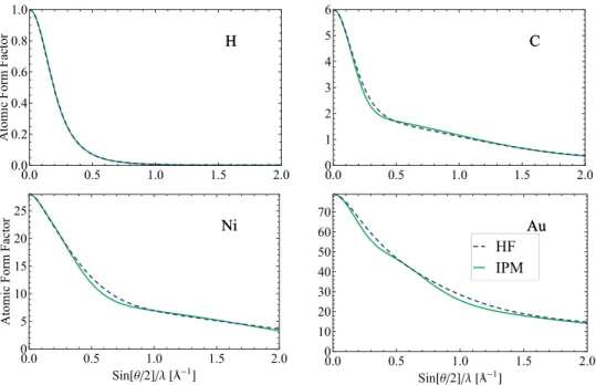
The Gaussian hypergeometric function in Eq. (7) can be evaluated analytically (see Eqs. (15.3.19) and (15.4.10) in Ref. 37). Equation (7) is the main result of this article: by setting the orbital effective nuclear charges, the electronic configuration, the projectile wave-vector, and the scattering angle, the atomic FF is analytically obtained. For example, in Fig. 1, we show the FFs of some selected elements as obtained from Eq. (7). The FFs are plotted against sin(θ/2)/λ, as usual in crystallography, whereλ=2π/k. IPM’s FFs are compared with HF’s. For light atoms, FFs obtained within IPM are hardly distinguishable from the ones obtained within HF. As the atomic number increases, the difference between the two calculations is, as expected, more significant. This is due to the fact that the cross terms of the type ∼RniliRnjli, which have been here neglected in the calculation of radial charge density Eq. (1), have non-negligible contribution in medium- and high-Zregimes when compared to the direct terms.
As an example, below, we shall apply Eq. (7) to evaluate the DCS for Rayleigh scattering by some selected neutral atoms.
IV. APPLICATION TO RAYLEIGH SCATTERING
FIG. 1. Atomic form factors for selected elements. HF’s and IPM’s calculations are compared.
as accurate as 1%, for a wide range of photons energies (approximately from 50 keV to 1.4 MeV45). Nevertheless, since precise SM calculations are computationally very demanding, FF approaches are very much used. A comparison between FF and SM approaches can be found elsewhere and will not be made here in detail (for details, see Refs.40and45). We briefly mention that although both SM and FF approaches have their own limitations depending on the energy of the incident photon, atomic number, atomic shell, and scattering angle, they provide DCS in good agreement with experimental data over limited intervals of these parameters.40More specifically, FF approach can be used provided that the photon energy be much larger than the atomic binding energies but much smaller than the electron rest-mass energy.26More accurate Rayleigh amplitudes for a wider photon energy range can be achieved within the FF approach by considering a modified form factor (MFF) and by considering the anomalous scattering factors usually denoted by f′andf′′.5,46
It must be underlined that both SM and FF approaches treat the target as an isolated atom (isolated atom approximation), with the electronic wave functions being obtained within IPA. This restricts their use in situations where electron correlations are important, such as at very low photon energy and when the atom is influenced by the environment, as it might be the case in solids or in a plasma. For coherent scattering by several atoms in a unit cell, the more general Bragg-Laue (BL) or Thermal Diffuse (TD) diffraction law must be used, which corresponds to the cases where the Bragg planes are aligned or misaligned, respectively. Both BL and TD diffraction laws depend on the atomic form factor through the crystal structure factor.5
Within the FF approach (or FF approximation), the DCS for elastic scattering of photons by an isolated atom is given by26
dσ
dΩ = r02
2 (1 +cos
2θ) |F(θ,k)|2, (10)
where r02
2 (1 +cos2θ)is the Thomson DCS andr0is the classical electron radius. Below, we shall
052105-6 Safariet al. J. Math. Phys.56, 052105 (2015)
TABLE I. Calculations for the DCS (b/sr) for Rayleigh scattering by selected elements 1≤Z≤82 in the ground state, for scattering angleθ=90◦and for selected energies. Our ANFF and HF results are compared with SM calculations,26NNFF
calculations,12and measurements. If not differently specified, the measurements of Mandalet al.47are shown for photon
energyE
γ=22.1 keV, while the measurements of Kumaret al.48are shown forEγ=59.54 keV. Numbers in parentheses are
the experimental errors, while numbers in squared brackets are powers of ten.
E
γ=22.1 keV Eγ=59.54 keV
This work This work
Element Measured SM NNFF HF ANFF Measured SM NNFF HF ANFF
1H . . . . . . 3.432[−7] 3.339[−7] 3.344[−7] . . . . . . 1.460[−10] 1.482[−7] 1.457[−10] 13Al . . . . . . 0.133 0.120 0.115 0.01633a
(0.00035)
0.0165 0.0169 0.0166 0.01621
28Ni 1.53 (0.13) 1.560 1.365 1.387 1.519 . . . . . . 0.106 0.097 0.095 30Zn 1.69 (0.15) 1.745 1.517 1.543 1.648 0.127
(0.006)
0.132 0.124 0.121 0.112
46Pd 4.20 (0.37) 3.845 5.206 5.364 4.188 0.555b
(0.028)
0.665 0.562 0.591 0.480
48Cd 4.90 (0.44) 5.019 6.045 6.211 5.005 0.709
(0.035)
0.752 0.622 0.665 0.553
50Sn 5.82 (0.50) 6.045 6.879 7.087 6.101 0.759
(0.038)
0.824 0.697 0.734 0.632
79Au 18.40 (1.66) 20.468 19.054 20.280 16.922 1.92 (0.10) 1.93 2.27 2.560 1.90 82Pb 20.79 (1.83) 22.853 21.683 23.055 18.509 2.38 (0.12) 2.27 2.64 3.009 2.13
aValue taken from Ref.49. bValue taken from Ref.50.
We calculated the DCS for Rayleigh scattering offsome selected elements in the ground state, for scattering angleθ=90◦
and for energies 22.1 keV and 59.54 keV. Our analytical nonrelativistic FF (hereinafter referred to as ANFF) DCSs and HF results are shown in TableIand compared with SM calculations of Kissel,26numerical NFF calculations of Hubbell12(hereinafter referred to as NNFF), and recent measurements of Mandalet al.47and Kumaret al.48As can be seen from TableI, for the energy value 22.1 keV, ANFF cross sections are inside the experimental error bars for all elements except for82Pb. In comparison, all SM cross sections are inside the error bars except for79Au and 82Pb (for 46Pd, the cross section is in the border). On the other hand, NNFF and HF calculations
are, in general, outside the experimental error bars and are in excellent agreement with each other. Another point which is worth to notice is that in the case of46Pd, our ANFF cross section describes
the measurement remarkably better than all other calculations. Comparison between ANFF and HF values shows that ANFF results agree better with experiments than HF results for photon energy Eγ=22.1 keV. The reason for this might be as follows: (i) in HF calculations, all parameters are
calcu-lated self-consistently. On the other hand, in the IPM, the effective nuclear charge is given as external parameter, which is calculated independently. This difference in procedure might be the reason for which our analytical formula is favorable with respect to HF and (ii) we must remember that the application of the FF to the DCS for light scattering is itself an approximation. Thus, the accuracy of FF, via either analytical or numerical methods, is not directly responsible for the discrepancies between experimental data and theoretical value. For the energy value 59.54 keV, SM calculations have in general better agreement with experiments than other calculations. This is not unexpected, since SM calculations numerically include the full contribution of the Rayleigh scattering second order amplitude, while NNFF, HF, and ANFF cross sections include only the leading part of it.26
V. FURTHER APPLICATIONS AND PROSPECTS
(i) Our nonrelativistic analytical treatment can be extended to the calculation of RFF by using Dirac hydrogenic wave functions. In fact, radial components of Dirac hydrogenic wave functions can be expressed in terms of associated Laguerre polynomials. By repeating the same analysis showed in this article for each component, one can derive the relativistic equivalent of Eq. (7). Relativistic effects in Rayleigh scattering offatoms are nonetheless expected to be small, as briefly discussed in Sec.IV(see also Ref.46, where relativistic effects in FF calculations are discussed to be not more than few percent, when momentum transfer is not very large).
(ii) The presented formalism of analytical FF may be directly generalized to CI numerical calculations. The CI atomic state function (ASF) is constructed as a linear combination of config-uration state functions (CSF) (or Slater determinants), where the coefficients of the expansion are obtained by diagonalizing the atomic Hamiltonian matrix within the chosen basis set. The present formalism would be of most use in CI calculations if the hydrogenic RWFs that appear in Eq. (2), and consequently in the CI expansion, are calculated using the same (i.e., non-varying) effective nuclear chargeZi. In fact, ifZiare the same for all RWFs, they form a complete orthogonal basis set (including the continuum part of the spectrum), and thus, the ASF approaches the precise solution of the Schrödinger equation, when the summation in CI expansion runs up to infinity. Therefore, the CI expansion whose weights are the FFs in (7) would lead to an exact result for the FF related to the ASF. On the other hand, if differentZiare used for each subshell, then the FF related to the ASF may be written as a linear combination of FFs presented in Eq. (7) only by neglecting the configuration cross contribution, which arise from off-diagonal matrix elements appearing in the single electronnl→n′lexcitation (or de-excitation).
(iii) In structural crystallography, the structure factor Fh, which may be written as a linear combination of FFs of the atoms in the unit cell,10,11is used to solve the crystallographic phase problem, and, therefore, to determine the crystal structure. Today, the number of solved structures (inorganic, organic, metallorganic, and biological tissues) is approaching one million and they are deposited in various databases.51–53The accuracy of the structural model is estimated by the crystal-lographic index,Rcryst, and then verified by means of chemical validation. Presently, the most
pop-ular atomic FFs used in crystallography are listed in the international tables for crystallography.14 Analytical expression (7) may be used as a possible alternative.
(iv) Our analytical expression for the atomic FF can be applied for studying other electrody-namical processes, such as electron scattering by atoms11,54or by nuclei, if the nuclear shell model is used with a central Coulomb-like potential.55
ACKNOWLEDGMENTS
The research leading to these results has received funding from the People Programme (Marie Curie Actions) of the European Union’s Seventh Framework Programme (FP7/2007-2013) under REA grant agreement n◦[291734]. F.F. acknowledges support by Fundação de Amparo à Pesquisa do estado de Minas Gerais (FAPEMIG), by Conselho Nacional de Desenvolvimento Científico e Tecnológico (CNPq), and by the Austrian Science Fund (FWF) through the START Grant No. Y 591-N16. F.F. acknowledges hospitality of the Néel institute in Grenoble (France), where part of the work has been carried out. L.S., K.J., and F.F. acknowledge support by the Research Council for Natural Sciences and Engineering of the Academy of Finland. P.A. acknowledges the support of the German Research Foundation (DFG) within the Emmy Noether program under Contract No. TA 740 1-1 and FCT, under Contract No. SFRH/BPD/92329/2013. J.P.S. and P.A. acknowledge support by Fundação para a Ciência e a Tecnologia (FCT) in Portugal, through the Project Nos. PEstOE/FIS/UI0303/2011 and PTDC/FIS/117606/2010. All authors gladly thank Professor Paul Indelicato, Professor Nivaldo Lucio Speziali, and Professor Carmelo Giacovazzo for discussions about possible applications of the presented results in structural crystallography.
1K. K. Sethet al.,Phys. Rev. Lett.110, 022002 (2013).
2Z. Ahmedet al.,Phys. Rev. Lett.108, 102001 (2012).
3J. C. Bernaueret al.,Phys. Rev. Lett.105, 242001 (2010).
4A. Courtoy, F. Fratini, S. Scopetta, and V. Vento,Phys. Rev. D78, 034002 (2008).
052105-8 Safariet al. J. Math. Phys.56, 052105 (2015)
6A. Tartari, A. Taibi, C. Bonifazzi, and C. Baraldi,Phys. Med. Biol.47, 163 (2002).
7B. W. Batterman, D. R. Chipman, and J. J. DeMarco,Phys. Rev.122, 68 (1961).
8A. Alataset al.,Phys. Rev. B77, 064301 (2008).
9R. Cesareoet al.,Phys. Rep.213, 117 (1992).
10C. Giacovazzoet al.,Fundamentals of Crystallography(Oxford Science Publications, 1992), Chap. 2.
11D. B. Williams and C. B. Carter,Transmission Electron Microscopy: A Textbook for Material Science(Springer, 2009),
Chap. 2 and 3.
12J. H. Hubbellet al.,J. Phys. Chem. Ref. Data4, 471 (1975).
13J. H. Hubbell and I. Øverbø,J. Phys. Chem. Ref. Data8, 69 (1979).
14A. J. C. Wilson and V. Geist,International Tables for Crystallography, Volume C: Mathematical, Physical and Chemical Tables(Kluwer Academic Publishers, Dordrecht, 1992), Chap. 6.1.
15D. Belkic,J. Phys. B16, 2773 (1983).
16D. Belkic,J. Phys. B17, 3629 (1984).
17D. Belkic and H. S. Taylor,Phys. Scr.39, 226 (1989).
18D. Belkic,Phys. Scr.45, 9 (1992).
19R. T. Brown,Phys. Rev. A1, 1342 (1970).
20R. S. Alassar, H. A. Mavromatis, and S. A. Sofianos,Acta Appl. Math.100, 263 (2008).
21D. Schaupp, M. Schumacher, F. Smend, P. Rullhusen, and J. H. Hubbell,J. Phys. Chem. Ref. Data12, 467 (1983).
22R. D. Cowan,The Theory of Atomic Structure and Spectra(University of California Press, Berkeley, 1981). 23W. Muhammad and S. H. Lee,PLoS One8, e69608 (2013).
24A. Bethe,Phys. Rev.87, 656 (1952).
25F. Smend and M. Schumacher,Nucl. Phys. A223, 423 (1974).
26P. P. Kane, L. Kissel, R. H. Pratt, and A. C. Roy,Phys. Rep.140, 75 (1986).
27B. H. Bransden and C. J. Joachain,Physics of Atoms and Molecules(Longman, 1983). 28F. Fratini,One- and Two-Photon Decays in Atoms and Ions(LAP, Saarbrücken, Germany, 2011).
29A. Surzhykov, A. Volotka, F. Fratini, J. P. Santos, P. Indelicato, G. Plunien, Th. Stöhlker, and S. Fritzsche,Phys. Rev. A81, 042510 (2010).
30E. Clementi and D. L. Raimondi,J. Chem. Phys.38, 2686 (1963).
31E. Clementi, D. L. Raimondi, and W. P. Reinhardt,J. Chem. Phys.47, 1300 (1967).
32Seehttp://www.webelements.comfor information about the effective nuclear charges (Ze f f).
33J. C. Slater,Phys. Rev.36, 57 (1930).
34A. Costescu, K. Karim, M. Moldovan, S. Spanulescu, and C. Stoica,J. Phys. B: At., Mol. Opt. Phys.44, 045204 (2011).
35W. T. Howell,Philos. Mag.24(7), 1082 (1937).
36L. Carlitz,J. London Math. Soc.36, 399 (1961).
37M. Abramowitz and I. A. Stegun,Handbook of Mathematical Functions With Formulas, Graphs, and Mathematical Tables,
National Bureau of Standards, Applied Mathematics Series (National Bureau of Standards, Superintendent of Documents, U.S. Government Printing, 1964).
38L. Kissel, R. H. Pratt, and S. C. Roy,Phys. Rev. A22, 1970 (1980).
39L. Kissel,Radiat. Phys. Chem.59, 185 (2000).
40S. C. Roy, L. Kissel, and R. H. Pratt,Phys. Rev. A27, 285 (1983).
41L. Safari, P. Amaro, S. Fritzsche, J. P. Santos, and F. Fratini,Phys. Rev. A85, 043406 (2012).
42L. Safari, P. Amaro, S. Fritzsche, J. P. Santos, S. Tashenov, and F. Fratini,Phys. Rev. A86, 043405 (2012).
43L. Safari, P. Amaro, J. P. Santos, and F. Fratini,Radiat. Phys. Chem.106, 271 (2015).
44V. Florescu, M. Marinescu, and R. H. Pratt,Phys. Rev. A42, 3844 (1990).
45S. C. Roy,X-Ray Spectrom.28, 376 (1999).
46S. C. Roy, L. Kissel, and R. H. Pratt,Radiat. Phys. Chem.56, 3 (1999).
47A. C. Mandal, D. Mitra, M. Sarkar, and D. Bhattacharya,Phys. Rev. A66, 042705 (2002).
48S. Kumar, V. Sharama, J. S. Shahi, D. Mehta, and N. Singh,Eur. Phys. J. D55, 23 (2009).
49E. Casnati, C. Baraldi, and A. Tartari,Phys. Rev. A42, 2627 (1990).
50P. Latha, K. K. Abdullah, M. P. Unnikrishnan, K. M. Varier, and B. R. S. Babu,Phys. Scr.85, 035303 (2012).
51Seehttp://www.ccdc.cam.ac.uk/products/csd/for the Cambridge Structural Database (CDS). 52Seehttp://www.fiz-karlsruhe.de/icsd_content.htmlfor Inorganic Crystal Structure Database (ICSD). 53Seehttp://www.rcsb.org/pdbfor Protein Data Bank.
54F. Fratini, L. Safari, A. G. Hayrapetyan, K. Jänkälä, P. Amaro, and J. P. Santos,Europhys. Lett.107, 13002 (2014).