Two-scale topology optimization of macrostructure and porous
microstructure composed of multiphase materials with distinct
Poisson’s ratios
Abstract
Negative Poisson’s ratio NPR material attracts a lot of attentions for its unique mechanical properties. However, achieving NPR is at the expense of reducing Young’s modulus. It has been observed that the composite stiffness can be enhanced when blending positive Poisson’s ratio PPR material into NPR material. Based on the respective interpolation of Young’s modulus and Poisson’s ratio, two concurrent topology optimization problems with differ-ent types of constraints, called Problem A and B, are respectively discussed to explore the Poisson’s ratio effect in porous microstructure. In Problem A, the volume constraints are respectively imposed on macro and micro struc-tures; in Problem B, besides setting an upper bound on the total available base materials, the micro thermal insulation capability is considered as well. Besides considering the influence of micro thermal insulation capability on the optimized results in Problem B, the similar and dissimilar influences of Poisson’s ratios, volume fractions in Problem A and B are also investigated through several 2D and 3D numerical examples. It is observed that the con-current structural stiffness resulting from the mixture of PPR and NPR base materials can exceed the concurrent structural stiffness composed of any in-dividual base material.
Keywords
Topology optimization, concurrent design, Poisson’s ratio, multiphase ma-terials
1 INTRODUCTION
With a near 30-year development, the structural topology optimization has emerged a variety of approaches including homogenization method Bendsøe and Kikuchi 1988 , solid isotropic material with penalization SIMP method Bendsøe 1989, Mlejnek 1992, Zhou and Rozvany 1991 , evolutionary structural optimization ESO method Xie and Steven 1993 and the updated version, bi-directional evolutionary structural optimization BESO method Querin et al. 2000 , level set method Wang et al. 2003 and phase field method Bourdin and Chambolle 2003 . Quite recently, an explicit topology optimization approach based on so-called moving morphable compo-nents MMC solution framework was presented by Guo, Zhang, and Zhong 2014 .
The concept of concurrent design can be traced to Lakes 1993 . The pioneering work of Rodrigues, Guedes, and Bendsoe 2002 was to introduce the topology optimization technique into concurrent design. However, any variable microstructure causes a high computational cost and manufacture difficulties. Later a more popular con-current design method was developed by Liu, Yan, and Cheng 2008 . In this method, uniform microstructure can be achieved which overcomes the issues mentioned above. During the optimization process, effective material
Jiao Jiaa, b* Wei Chengc Kai Longd
a Department of Automotive Engineering, School
of Transportation Science and Engineering, Bei-hang University, Beijing 100191, China. E-mail: [email protected]
b Advanced Vehicle Research Center AVRC ,
Bei-hang University, Beijing 100191, China
c School of Aeronautic Science and Engineering,
Beihang University, Beijing 100191, China. E-mail: [email protected]
d State Key Laboratory for Alternate Electrical
Power System with Renewable Energy Sources, North China Electric Power University, Beijing 102206, China. E-mail: [email protected]
* Corresponding author
http://dx.doi.org/10.1590/1679-78254991
2008 suggested that the structure composed of porous material has lower stiffness than the fully solid material structure. Moreover, Niu, Yan, and Cheng 2009 also observed that the structure without porosity on micro-scale has higher fundamental frequency than the structure with porosity on micro-scale. A similar viewpoint is expressed in literature Vicente et al. 2016 . Taken minimized frequency response as the objective, under the BESO framework,
Vicente et al. 2016 revealed that the fully solid material structure has a better result compared to the structure consisted of porous microstructure. The same conclusion can be obtained through porous microstructure converg-ing to isotropic solid material under coupled volume constrains Sivapuram, Dunnconverg-ing, and Kim 2016 . The above researches manifest that the structure made of porous material should consider the multifunctional demands. Bas-ing on this idea, Yan, Cheng, and Liu 2008 , Deng, Yan, and Cheng 2013 , Yan et al. 2014 and Long, Wang, and Gu 2018 discussed the concurrent optimization of thermoelasticity and thermal conduction. Besides the discussion about the multifunctional applications, the concurrent approaches in considering multiphase materials are con-cerned as well in recent years. Especially Xu et al. Xu, Jiang, and Xie 2015, Xu and Xie 2015, Xu et al. 2016 built the concurrent optimization models in regard to multiphase materials respectively under harmonic, random and me-chanical-thermal coupled loads. Da et al. 2017 focused on the super multiphase materials problem in concurrent optimization. Besides the homogenization theory, other approaches are also employed in concurrent optimization. Basing on super element technique, Zhang and Sun 2006 achieved the scale-related cellular materials and layered structures. Yan, Hu, and Duan 2015 adopted extended multiscale finite element method to study the size-effect in concurrent structure which is composed of lattice materials. Xia and Breitkopf 2014 introduced FE2 model into
concurrent optimization to solve the computational cost problem caused by multiscale nonlinearity.
Recent researches indicate that exceptional Poisson’s ratios, e.g., Poisson’s ratio towards to the thermody-namic limit 0.5, negative Poisson’s ratio NPR , are helpful to improve the composite stiffness, called as Poisson’s ratio effect Liu, Zhang, and Gao 2006, Lim 2010 . Moreover, when Young’s moduli of the positive Poisson’s ratio PPR and NPR base materials are close to each other, the maximum enhancement in stiffness is observed to happen with the PPR and NPR respectively approaching to the thermodynamic limits 0.5 and -1 Kocer, McKenzie, and Bilek 2009 . Successive investigations validate that Poisson’s ratio effect is influenced by Poisson’s ratio, Young’s modu-lus, dosages, shapes and distributions of base materials Zuo and Xie 2014, Shufrin, Pasternak, and Dyskin 2015 . Young’s modulus and Poisson’s ratio are respectively interpolated for employing topology optimization technique to exploit Poisson’s ratio effect in sandwich structured composites Strek et al. 2014 . Besides maximizing the ef-fective Young’s modulus Long et al. 2016 , Long et al. Long, Han, and Gu 2017, Long et al. 2018 extended the above model to reveal the Poisson’s ratio effect in concurrent structure under volume fraction constraint and mass constraint.
In this paper, basing on the respective interpolation of Young’s modulus and Poisson’s ratio, Poisson’s ratio effect in porous microstructure is revealed. Taken structural compliance as the objective, two optimization prob-lems with different types of constraints, named as Problem A and B, are respectively discussed. In Problem A, the independent volume constraints are respectively imposed on macro and micro structures; in Problem B, besides setting an upper bound on the total available base materials, the thermal insulation capability in microstructure is also considered. The effective elasticity and thermal conductivity matrices obtained from the homogenization tech-nique are respectively used in macro structural analysis and micro thermal insulation constraint. The remainder of the paper is organized as follows. Two concurrent optimization problems considering Poisson’s ratio effect are established and described in Section 2. Section 3 provides the sensitivity analyses. The numerical implementation is given in Section 4. Section 5 presents several 2D and 3D numerical examples to illustrate the proposed models are effective to reveal the Poisson’s ratio effect in concurrent optimization. Concluding remarks are given in Section 6.
2 CONCURRENT TOPOLOGY OPTIMIZATION PROBLEM WITH PPR AND NPR MATERIALS
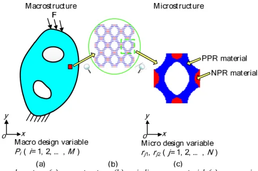
Considering a two-scale system, as shown in Fig. 1, the macrostructure Fig. 1 a is comprised of periodic materials Fig. 1 b whose unit cell Fig. 1 c is constituted by isotropic PPR and NPR base materials. The micro-structure is assumed to be orthotropic. In Fig. 1 c , the PPR and NPR base materials are respectively represented by blue and red.
P
iP
iÎ
[ ,1]
d
,i
1, 2, …, M, M is the total number of elements on macro-scale is taken as the macro design variable, with representation of the relative density of thei
th
macro element.d
is a smallpredeter-mined value to avoid numerical singularity in optimization whose value is 0.001 in this paper.
r
j1 andr
j21
[ ,1]
j
where
r
j1 characterizing the given micro element is solid materialr
j1=
1
or voidr
j1=
d
, andr
j2 represent-ing the existence of PPRr
j2=
1
or NPRr
j2=
0
base material. Adopting the structural compliance as the ob-jective, two kinds of concurrent optimization problems are discussed to reveal the Poisson’s ratio effect. In Problem A, the independent volume fraction constraints are imposed on macrostructure and microstructure; in Problem B, besides the coupled volume relationship between the macrostructure and microstructure, the thermal insulation constraint is conducted on micro-scale.Figure 1: A two scale system: a macrostructure; b periodic porous material; c porous microstructure.
2.1 Problem A
In Problem A, the independent volume constraints are imposed on macrostructure and microstructure, the corresponding mathematical formula can be expressed as
1 2
1
mac mac mac
1
mic,b mic mic,b
1 1
mic,b1 mi
1 2
Find : { , , }( 1,2,..., ; 1,2,..., )
Minimize:
Constraint I :
Constraint II : /
Constraint III /
Constraint IV /
:
:
i j j
M T
i i i
i
M
i i i
N
j j
j
j j j
P r r i M j N
C
f PV V f
f r V V f
r r V V
f
==
=
= = =
=
=
= £
= £
=
å
å
å
X
U K U
KU F
c mic,b1
1
N
j
f =
ìïï ïï ïï ïï ïï ïï ïï ïïï íï ïï ïï ïï ïï ïï
ïï £
ïï
ïïî
å
1
where
C
denotes the macro structural compliance.U
i and U present the macro elemental and nodal displacement vectors, respectively.K
i and K are the macro elemental and global stiffness matrices, respectively. F is the external load vector applied on the macrostructure.Constraint II defines the dosages of porous materials on macro-scale. Vi and
mac
V respectively characterize
Constraint III and IV respectively set the upper bounds on total base materials and PPR base material in mi-crostructure.
V
j andmic
V represent the jth elemental volume and the volume of the micro design domain.
f
mic,band
f
mic,b1 are the prescribed volume fractions of base materials and PPR base material on micro-scale.As known in Eq. 1 , the volume fractions of the macrostructure and microstructure are respectively defined and there is no coupling relationship between the macro and micro design variables. That is to say the porous re-quirement on micro-scale is mandatory.
2.2 Problem B
In Problem B, the total dosages of the base materials and micro thermal insulation capability are simultane-ously defined. The concurrent optimization model can be correspondingly expressed as
1 2
1
1 1
b 1 b
mac mic
1 2 1
b1 1 b1
mac mic
Find : { , , }( 1,2,..., ; 1,2,..., )
Minimize:
Constraint I :
Constraint II :
Constraint III 1 Constraint IV 2
:
:
i j j
M T
i i i
i N M j j i i j i N M
j j j
i i j i
P r r i M j N
C
r V PV
f f
V V
r r V PV f f V V = = = = = = = = = = = £ = £
å
å
å
å
å
XU K U
KU F 2 H lim 1 ss s k k = ìïï ïï ïï ïï ïï ïï ïï ïï ïï ïï íï ïï ïï ïï ïï ïï ïï ïï ïï £ ïï ïî
å
2In Eq. 2 , Constraint II and III respectively set the dosages of the base materials and PPR base material in macro and micro design domains. That is to say the macro and micro design variables have strong coupling rela-tionship in volume fraction constraints.
Constraint IV describes the thermal insulation capability related to the microstructure. As to orthotropic ma-terial, the thermal insulation capability can be appraised according to the average of the diagonal elements in the effective thermal conductivity matrix de Kruijf et al. 2007 .
k
ssH is thes
th
diagonal element in the effective thermalconductivity matrix.
k
lim is the upper bound of the thermal conductivity. Actually, the thermal insulation con-straint can also be understood as a porous requirement like volume fraction concon-straint, which not only restricts the dosages of the base materials on micro-scale but also plays a role of connecting the base materials.2.3 Material interpolation scheme
2.3.1. Material interpolation scheme for structural analysis
Using SIMP scheme, the Young’s modulus and Poisson’s ratio in micro element
j
can be written as(1) (2) 1( 2 (1 2) )
j j j j
E =ra r Ea + -ra E 3a
(1) (2) 2 (1 2)
j j j
v =r vb + -rb v 3b
in which E and v respectively denote the Young’s modulus and Poisson’s ratio. Superscript numbers 1 and 2 characterize the PPR and NPR base materials, respectively. The penalization factors have the values of
a
=
4
and1
b= for better convergence and clearer topologies Long et al. 2016 .
2
/ (1 ) j E vj j vj
l = - 4a
/(2(1
))
j
E
jv
jm
=
+
4bIn 3D problem, the first Lamé’s parameter needs to be modified as
l
i=
E v
i i/(1
+
v
i)/(1 2 )
-
v
i , while the secondLame’s parameter
m
j is kept the same with Eq. 4b .With the help of Eq. 4 , the elasticity matrix in microstructure can be split into
MI
j l j m
l m
= +
D D D 5
where
D
l andm
D
are the constant matrices with the expressions of1 1 0 1 1 0 0 0 0
l
é ù ê ú ê ú = ê ú ê ú ê ú ë û
D ,
2 0 0 0 2 0 0 0 1
m
é ù ê ú ê ú = ê ú ê ú ê ú ë û
D in 2D plane
stress problem, and
1 1 1 0 0 0 1 1 1 0 0 0 1 1 1 0 0 0 0 0 0 0 0 0 0 0 0 0 0 0 0 0 0 0 0 0 l é ù ê ú ê ú ê ú ê ú ê ú
= ê ú
ê ú ê ú ê ú ê ú ê ú ë û D ,
2 0 0 0 0 0 0 2 0 0 0 0 0 0 2 0 0 0 0 0 0 1 0 0 0 0 0 0 1 0 0 0 0 0 0 1 m é ù ê ú ê ú ê ú ê ú ê ú
= ê ú
ê ú ê ú ê ú ê ú ê ú ë û
D in 3D problem.
Effective elasticity matrix DH can be calculated by the numerical homogenization theory with the format of
Lamé’s parameters Andreassen and Andreasen 2014, Hassani and Hinton 1998
H
1
(
)(
)
d
|
V
|
Vl
j l+
m
j mV
=
ò
D
D
I
-
bu
D
6where |V| is the volume of unit cell; I is the identity matrix; b is the micro strain-displacement matrix; the micro displacement field u can be acquired through the FE analysis with applying the periodic boundary conditions within the unit cell
(
T M I d)
T M IdV V = V V
ò
b D b uò
b D 7The right hand side in Eq. 7 defines the external forces corresponding to the uniform strain fields, e.g., two normal unit strains in x and
y
directions and one shear unit strain for 2D cases, and three normal unit strains in x,y
andz directions and three shear unit strains for 3D cases.The macro elasticity matrix can be determined by the following interpolation
MA p H
i
=
P
iD
D
8where the penalization factor p retains the typical value of 3.
From the above analysis, effective elasticity matrix DH plays a connection role between macrostructure and
microstructure.
On macro-scale, FE analysis is again performed to obtain the displacement vector. The macro global stiffness matrix
K
can be assembled by the elemental stiffness matrixi
K
T MA
1 i
M M
i V i i
i i
dV
=
=
å
=åò
K K B D B 9
2.3.2 Material interpolation scheme for thermal insulation constraint
When considering the Problem B, the effective thermal conductivity of the porous microstructure is needed. Similarly, the elemental thermal conductivity can be interpolated with the SIMP scheme
(1) (2) 1( 2 (1 2) )
j rj rj rj
g g g
k = k + - k 10
where k(1) and k(2 ) are respectively used to represent the thermal conductivity of PPR and NPR materials. It is
supposed that k(1) > k(2 ).
g
is the penalization factor with the value of 4 Jia et al. 2016 .Furthermore, the micro thermal conductivity matrix can be obtained as
MI 0
j
k =kk 11
where
k
0is the basic thermal conductivity matrix when thermal conductivity is 1.Similarly, the effective thermal conductivity matrix kH can also be evaluated through the numerical
homoge-nization method
χ
H
1
MI(
)d
|
V
|
V sV
=
ò
-k
k
I
12where Is represents the identity matrix in the process of thermal conductivity homogenization;
χ
denotes the induced temperature gradient field which can be computed from the uniform gradient temperature fields.More details in implementation of homogenized elasticity and thermal conductivity matrices can be referred to literature Andreassen and Andreasen 2014 .
3 SENSITIVITY ANALYSES FOR MACROSTRUCTURES AND MICROSTRUCTURES
Basing on the adjoint variable method Haug, Choi, and Komkov 1986 , the derivatives of the objective to the design variables can be calculated as
T 1 T T H
i
p
i i V i i
i i C pP dV P P -¶ ¶ = - =
-¶ 
ò
K
U U U B D B U 13
H
T T T T
1 1 i
M M
p i
i i i i V i i
i i
jk jk jk jk
C
P dV
r r = r = r
¶ 
¶ = - ¶ = - =
-¶ 
å
¶å
ò
¶D K
K
U U U U U B B U 14
According to the mapping method Liu et al. 2002 , the expression of H
jk
r
¶D 
k
1, 2 in Eq. 14 can be writtenas
H MI
T
1
( ) ( )
| | V
jk jk
dV
r V r
¶ = - 
-
ò
¶D D
I bu I bu 15
With the aid of Eq. 5 , the above equation can be further given as
H T T 1 1 ( ) ( ) ( ) ( ) | | | | j j V V
jk jk jk
dV dV
r V r l V r m
l m
¶ 
¶ = - - + -
-
ò
¶ò
¶D
I bu D I bu I bu D I bu 16
in which
l
j
r
jk and
m
j
r
jk can be attained by the chain rulej j j j
j jk
j jk j jk
E v
r
E r v r
l l
l ¶ ¶ ¶ 
¶ ¶ = +
j j j j j jk
j jk j jk
E v
r
E r v r
m m
m ¶ ¶ ¶ 
¶ ¶ = +
¶ ¶ ¶ ¶ 17b
where
l
j
E
j has distinct expressions in 2D plane stress and 3D problems, as2
/ (1 ) j Ej vj vj l
¶ ¶ = - 2D plane stress 18a
/ (1
)/ (1 2 )
j
E
jv
jv
jv
jl
=
+
-
3D 18bFurthermore, the expression of
E
j
r
jk in Eq. 17 can be calculated as( 1) (1) (2)
1 1 ( 2 (1 2))
j j j j j
E r pra- E ra E ra
¶ ¶ = + - 19a
( 1) (1) (2) 2 1 2 ( )
j j j j
E r pr ra a- E E
¶ ¶ = - 19b
Similar as
l
j
E
j,
l
j
v
j also possesses distinct expressions in 2D plane stress and 3D problems, as2 2 2
(1 ) / (1 ) j vj Ej vj vj l
¶ ¶ = + - 2D plane stress 20a
2 2 2
(1 2 ) / (1 ) / (1 2 ) j vj Ej vj vj vj l
¶ ¶ = + + - 3D 20b
For
r
j1 is independent ofv
j , it only has( 1) (1) (2) 2 2 ( )
j j j
v r qr b- v v
¶ ¶ = - 21
In Eq. 17b ,
m
j
E
j and
m
j
v
j can be respectively derived from Eq. 4b1/(2(1
))
j
E
jv
jm
=
+
222
/ (1 ) / 2 j vj Ej vj m
¶ ¶ = - + 23
Eqs. 14 - 16 clearly indicate that the sensitivity expressions for micro design variables are split into two parts with the help of Lamé’s parameters, which simplifies the deduction process and programming.
In Problem A, the derivatives of volume fractions with the design variables on macro and micro scales can be respectively given as
mac mac i i f V V P ¶ = ¶ , mac 1 0 j f r ¶ = ¶ , mac 2 0 j f r ¶ =
¶ 24
mic,b 0 i f P ¶ = ¶ , mic,b mic 1 j j V f r V ¶ = ¶ , mic,b 2 0 j f r ¶ =
¶ 25
mic,b1 0 i P
f
= ¶¶
, mic,b1 2 mic 1 j j j r V r Vf
= ¶¶
, mic,b1 1 mic 2 j j j r V r Vf
= ¶¶
261 b 1 mac mic N j j j i i r V V f
P V V
=
¶ = 
å
, b 1
mac mic 1 M i i j i j PV V f
r V V
=
¶ = 
å
, b
2 0 j f r ¶ =
¶ 27
1 2 b1
1 mac mic
N
j j j j
i
i
r r V V
f
P V V
=
¶ = 
å
, b1 1 2
mac mic 1 M i i j j i j PV r V f
r V V
=
¶ =
å
, b1 1 1
mac mic 2 M i i j j i j PV r V f
r V V
=
¶ =
å
28
Moreover, the derivatives of H
ss
k
with respect to design variables are needed. Due to Hss
k
is independent of the macro design variableP
i, ¶kssH ¶Pi =0. With the help of Eqs. 10 and 11 , the derivatives ofH
ss
k
with respect tor
jkcan be written as
χ χ
( 1) (1) (2) H
1 2 2 T
0 1
( (1 ))
( ) ( )
| | j
j j j s s s s
ss
j j j
V j
r r
dV
r V
g g g
g k g k
k - +
-
= -
-
ò
I k I 29aχ χ
( 1) (1) (2) H
1 2 T
0 2
( )
( ) ( )
| | j
j j s s s s
ss
j j j
V j r dV r V g g
g g k k
k -
-
= -
-
ò
I k I 29b4 NUMERICAL IMPLEMENTATION AND PROCEDURE
In this article, the heuristic sensitivity filtering technique Sigmund 1997 is adopted to eliminate checker-board patterns and mesh dependence.
For design variables
P
i andr
j1 respectively representing the material or void on macro and micro scales, the classical mesh-independency filter with weighting the element density is employed. TakenP
i as an example1
i i
ie e e R
i i ie e
e R
C C
H P
P P H Î P
Î
¶ = 
å
å
¶ 30where
R
i is the set of elements e for which the center-to-center distance D( )
i e, to elementi
is smaller than the filter radiusr
min andH
ie is a weight factor determined by( )
(
min)
max 0, ,
ie
H = r - D i e 31
For
r
j2 is no longer a simple density variable and the suggested filter should be expressed as Sigmund 20012 2 1 j j je e N
j je e
e N
C C
H
r H Î r
Î
¶ 
=
å
å
¶ 32Averaging of the sensitivities will produce blurry boundaries in final topologies. For eliminating the intermediate density, the filtering programs are terminated after
||
X
( 1)l+-
X
( )l|| / ||
X
( 1)l+|| 0.5%
£
, whereX
= È
P
r
{ ,
P i
i1, 2, ...,
M
}
=
=
P
;{ ,
1, 2, ..., ;
1, 2}
jk
r
j
N k
=
=
=
r
andl
stands for the current iteration. Then theoptimization procedure will continue without filtering until || (Xl+ -1) X( ) || / || (l Xl+1) || 0.1%£ .
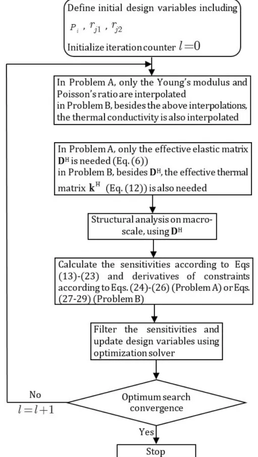
Key steps for the concurrent design of macrostructure and microstructure with PPR and NPR base materials are given in Fig. 2.
5 ILLUSTRATIVE EXAMPLES AND DISCUSSIONS
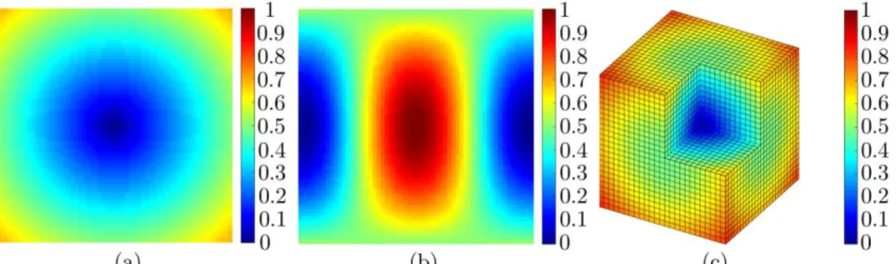
In this section, we present several 2D and 3D numerical examples for concurrent design with considering the Poisson’s ratio effect in concurrent structure. Where two 2D examples and one 3D example are discussed in Prob-lem A corresponding to two 2D examples for ProbProb-lem B. For easier discussions, the structural sizes, material prop-erties and external loads are all dimensionless. In 2D examples, the microstructure is discretized into 60 60 4-node quadrilateral elements, and 26 26 26 8-4-node solid elements in 3D example. The macro element edge is 1. As shown in Fig. 3, two types of non-uniform initial distributions on micro-scale are adopted in this study. Where initial design I and II are applied in 2D problem and initial design III is used in 3D problem. The density in initial design I and III is proportional to the distance from the element center to the center of the microstructure. The initial design II originates from the literature Zhou et al. 2012 . In Problem A,
r
j1 starts from the initial design I 2D or III 3D and rj2 starts from the uniform density distribution. In Problem B,r
j1 starts from the initial design II andr
j2 starts from the initial design I.Figure 3: Density distribution in micro design domain: a initial design I; b initial design II; c initial design III.
For ensuring close Young’s moduli to each other, the base materials are assumed to be polymers and designed in the form of porous microstructures. In all the numerical examples, the Young’s modulus of the base material 1 is defined as E(1) = 2.1. The Poisson’s ratio of the base material 1 is supposed to be v(1) =0.4 in the first four
exam-ples and v(1) = 0.35 in the last example. For easy identification, PPR and NPR base materials in microstructures are
respectively plotted in blue and red. Although the strategy with overcoming intermediate densities is adopted, a handful of intermediate densities still exist in the final topologies. For more meaningful comparisons, all the opti-mized results are executed with the 0-1 post processing Sigmund and Maute 2013 .
5.1 Problem A
In Problem A, the Young’s modulus of the base material 2 is set as (2) 1.8
E = .
Example I
The Poisson’s ratio effect in concurrent design is illustrated in this example. As shown in Fig. 4, the dimensions of the macro design domain are: length L 50, height H 100. The left edge is fully constrained and subjected to a vertical downward load, F 10, at the center of the right edge.
v
( )2 is allowed to vary from -0.4 to -0.9. The targetmacro and micro volume fractions are predefined as
f
mac 50%,f
mic,b 50% andf
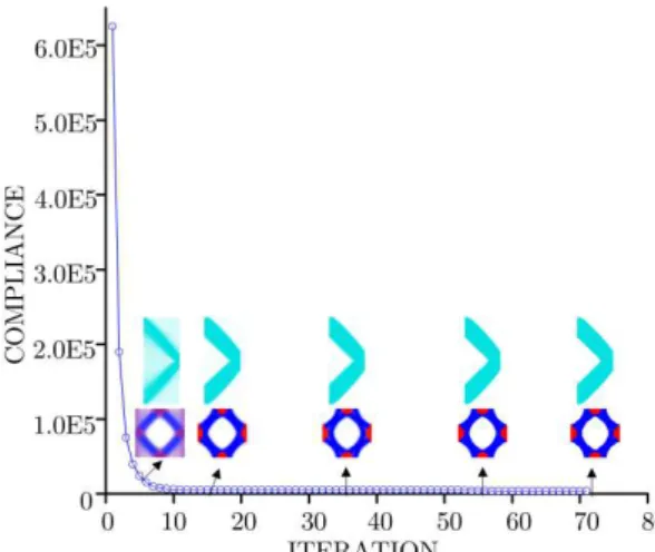
mic,b1 40%.Fig.5 plots the evolution histories of the macro and micro densities with
v
( )2 -0.4. This process clearlyillus-trates that the macrostructure and microstructure rapidly converge to stable topologies within fewer iteration steps. Fig. 6 provides the resulting compliance under various v( )2 . Several quintessential topologies with v( )2
-0.4, -0.6, -0.7 and -0.9 are inserted above the resulting compliance curve. For the sake of comparison, the optimized results with exclusive NPR base material are also presented in Fig. 6. At the mean time, the optimized macrostruc-ture and microstrucmacrostruc-ture from exclusive PPR base material are shown in Fig. 7. The corresponding compliance is
C
compliance occurs when the difference of v( )1 and v( )2 reaching the maximum v( )1 0.4 and v( )2 -0.9 in this
example .
Figure 4: A 2D cantilever beam for example I with length L 50, height H 100.
Figure 7: The optimized results composed of exclusive PPR base material: a macrostructure; b microstructure.
Example II
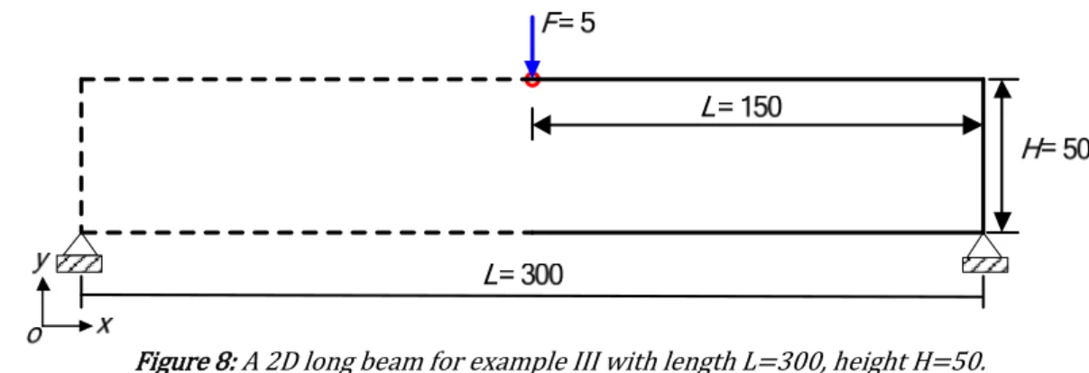
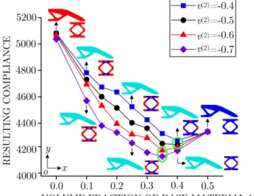
In this example, a long beam is optimized to investigate the influence of volume fractions on the final solution. As shown in Fig. 8, the overall sizes of the macro design domain are: length L 300, height H 50. A concentrated downward load is applied vertically at the center of the top edge with the bottom corners fully fixed. Considering the symmetry, only right half of the structure is used for optimization and result discussion. The load magnitude on the half beam is assumed to be F 5. The permitted variation ranges of v( )2 are from -0.4 to -0.7. The volume
frac-tion of PPR base material on micro-scale
f
mic,b1 changes from 10% to 40% whilef
mac andf
mic,b are both fixed at 50%.Figure 8: A 2D long beam for example III with length L 300, height H 50.
Fig. 9 provides the variation trend of resulting compliance under various
f
mic,b1. Moreover, the resulting to-pologies withf
mic,b1 10%, 25% and 40% when v( )2 -0.4, -0.7 are inserted at intervals in Fig. 9. To aidcompari-sons, the objective values and topologies with exclusive PPR and NPR base materials only v( )2 -0.4 are included
as well in Fig. 9. All the detailed data are summarized in Table 1. Unlike the Poisson’s ratio, in Fig. 9, the resulting compliance does not present a monotonic relationship with increasing of
f
mic,b1, i.e., there is an optimalf
mic,b1 cor-responding to the minimum compliance with a fixed v( )2 . In addition, from Fig. 9 and Table 1, it is observed thatthe optimal volume fraction
f
mic,b1 varies with v( )2 . The detailed variations of mic,b1f
are followed as: as to v( )2-0.4 and v( )2 -0.5, the summit of the resulting compliance occurs when
f
mic,b1 is approximately 40%, and as to( )2
v -0.6 and v( )2 -0.7, the minimum resulting compliance transfers to near
f
mic,b1 35%. This is primarily dueto the stiffness of NPR base material is improved when v( )2 is constantly decreasing. Furthermore, the ranges of
mic,b1
f whose objective values can exceed the results of exclusive PPR and NPR base materials are gradually
en-larged with decreasing of v( )2 , i.e.,
f
mic,b1 varies 35% to 40% when v( )2 -0.4 and v( )2 -0.5,f
mic,b1 varies from25% to 40% when v( )2 -0.6, and
f
mic,b1 varies from 20% to 40% when v( )2 -0.7. For clarity, the objective valuesFigure 9: The influence of the volume fraction of base material 1 on the resulting compliance.
Table 1: The resulting compliance under various mic,b1 f .
mic,b1
f
%Resulting compliance when v( )2 -0. 4
Resulting compliance when v( )2 -0.5
Resulting compliance when v( )2 -0.6
Resulting compliance when v( )2 -0.7
0 5081.84 5076.73 5066.70 5036.28
10 4781.77 4730.34 4694.58 4569.17
15 4673.54 4600.76 4532.29 4381.39
20 4636.04 4515.19 4396.53 4329.66
25 4524.70 4403.61 4315.74 4249.85
30 4426.43 4361.56 4288.50 4178.48
35 4321.60 4246.08 4193.36 4148.40
40 4271.43 4237.43 4216.97 4191.12
50 4335.96 4335.96 4335.96 4335.96
Example III
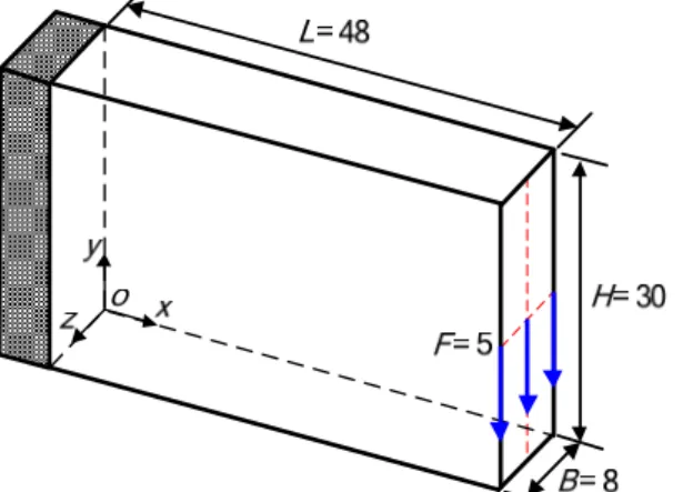
A 3D cantilever beam is optimized in this example to demonstrate the adaptability of the proposed model in 3D concurrent design. Fig. 10 shows the admissible design domain in macrostructure with sizes of length L 48, height H 30, and width B 8. The left hand side surface is fully constrained and an evenly distributed load F 5 is applied at the middle of the right surface. The Poisson’s ratio of the base material 2 is set as v( )2 -0.7. The volume
fraction constraints at two scales are set as fm ac 30%, fmic,b 80%, and fmic,b1 40%.
Table 2 lists the resulting two-scale topologies and effective elasticity matrix from hybrid of PPR and NPR base materials. At the mean time, the results of traditional structures made of exclusive PPR and NPR base materials with identical macro volume constraint fm ac 30% are provided as well in Table 2. According to the previous
Figure 10: A 3D cantilever for example III with length L 48, height H 30 and width B 8.
Table 2: The comparisons of concurrent structure and traditional structure.
mic,b
f % fm ic,b 1 % Resulting
compliance structure Macro- structure Micro- Elasticity matrix
100 100 7021.37
80 40 6125.68
2.5683 -0.0935 -0.1389 0.0000 0.0001 0.0000 -0.0935 2.0672 0.4953 -0.0000 0.0002 0.0000 -0.1389 0.4953 1.1611 -0.0000 0.0000 0.0000 0.0000 -0.0000 -0.0000 1.1608 -0.0000 0.0000 0.0001 0.0002 0.0000 -0.0000 0.6976 -0.0000 0.0000 0.0000 0.0000 0.0000 -0.0000 0.9563
é ù
ê ú
ê ú
ê ú
ê ú
ê ú
ê ú
ê ú
ê ú
ê ú
ê ú
ê ú
ë û
100 0 6982.06
5.2 Problem B
In Problem B, Young’s modulus of the base material 2 is assumed to be E( )2 1.7. The thermal conductivities of the base materials are kept to be (1)
6
k = , (2)
4
k = . The total dosages of the base materials are fixed at
f
b 50%.mic,b2
f
is used to represent the volume fraction of the base material 2 in microstructure. Example IVThe influences of NPR and volume fraction b1
f are investigated in this example. As shown in Fig. 11, the macro
design domain has sizes of length L 160, height H 100 with the same boundary condition and external load as illustrated in example I. Poisson’s ratio of the base material 2 is set to be v( )2 -0.3, -0.4 and -0.6, respectively. b1
f is
Figure 11: A 2D cantilever beam for example IV with length L 160, height H 100.
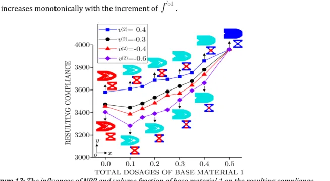
Fig. 12 supplies the resulting compliance under various
f
b1. In addition, several typical topologies withf
b1 10%, 20%, 30% and 40% when v( )2 -0.6 are inserted in Fig. 12. For comparison, the optimized results withex-clusive base material 1 and 2 only v( )2 -0.6 are also given in Fig. 12. All the detailed data are summarized in Table 3. From Fig. 12, it is can be easily found that the macro and micro structures respectively exhibit the disparate topological configurations with increasing of
f
b1. In order to manifest the stiffness enhancement is not caused by the variations of the macro and micro topological configurations, the optimized results with v( )2 0.4 are also pre-sented in Fig. 12. In Fig.12, it is noted that the resulting compliance from exclusive base material 2 is lower than the value of exclusive base material 1. Moreover, when v( )2 0.4, the minimum resulting compliance from multiphase materials is found to be between the values of exclusive base material 1 and 2, i.e., the concurrent stiffness is not be enhanced by blending two PPR base materials. However, when v( )2 -0.3, -0.4 and -0.6, the resulting stiffness can be enhanced at certain ranges off
b1. The above analysis proves that the stiffness enhancement is caused by the hybrid of PPR and NPR base materials. Similar with the Problem A, in Problem B the resulting compliance also decreases monotonically with the decrement of v( )2 from -0.3 to -0.6 . Moreover, with the reduction of v( )2, theranges of
f
b1 for enhanced stiffness are keeping expanding, i.e.,f
b1 is equal to 10% when v( )2 -0.3, b1Table 3: The resulting compliance under various fb1 when v( )2 0.4, -0.3, -0.4 and -0.6.
b1 f %
Resulting compliance when v( )2 0. 4
Resulting compliance when v( )2 -0.3
Resulting compliance when v( )2 -0.4
Resulting compliance when v( )2 -0.6
0 3580.15 3473.04 3455.35 3404.13
10 3610.49 3444.89 3386.12 3283.07
15 3630.29 3480.43 3434.12 3358.06
20 3686.04 3532.51 3483.96 3391.87
25 3693.22 3585.78 3551.08 3424.85
30 3717.45 3633.84 3570.02 3511.59
35 3752.09 3678.20 3641.47 3594.40
40 3857.64 3779.87 3736.58 3661.57
50 3959.25 3959.25 3959.25 3959.25
When v( )2 0.4, -0.6, the distributions of the base materials in microstructures seem different especially under larger b1
f , e.g., fb1 30% and 40%. For better illustration, taken fb1 40% as an example, the objective value is
revaluated after exchanging the material parameters for each other, i.e., respectively take v( )2 0.4 and v( )2 -0.6
into the topologies of hybrid of PPR and NPR base materials and hybrid of two PPR base materials. The detailed data are listed in Table 4. The comparisons show that both the original optimized results have lower compliance values which illustrates that with the variation of v( )2, the diverse distributions of base materials seem reasonable. This is mainly due to the stiffness of the base material 2 changes with the variation of v( )2.
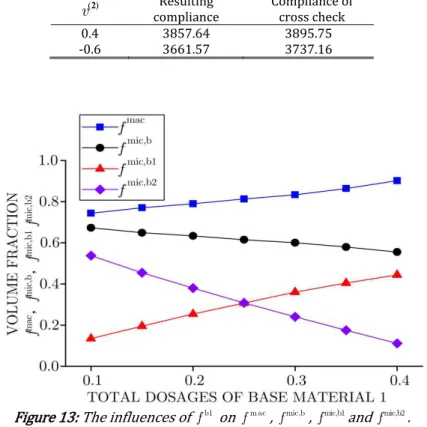
Taken v( )2 -0.3 as an example, the trends of m ac
f , fmic,b, fm ic,b1 and fm ic,b2 under various fb1 are shown in Fig.
13. In Fig. 13, it is observed that with b1
f varying from 10%-40%, fm ac and fm ic,b1 increase while fmic,b and fm ic,b2
decrease. According to the Constraints II and III in Eq. 2 , fixed b
f and increased fb1 result in more PPR base
materials distributing on micro-scale. At the mean time, due to the thermal insulation constraint having no change, less NPR base materials are required in microstructure. Consequently, even with fm ic,b1 continuously increasing,
mic,b
f still demonstrates a decline trend for degressive fm ic,b2. Finally, fm ac presents an uptrend because of fixed fb
and decreased fmic,b.
Table 4: Cross checks for v( )2 0.4 and v( )2 -0.6.
( )
v2 compliance Resulting Compliance of cross check
0.4 3857.64 3895.75
-0.6 3661.57 3737.16
Figure 13: The influences of b1
Example V
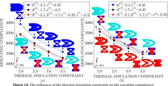
This example is the extension of example IV, with an attempt to reveal the influence of thermal insulation con-straint on the final results. The design domain, boundary condition and external load are kept the same with the example IV. The Poisson’s ratio of the base material 2 is set as v( )2 -0.5, and the total dosages of the base material 1 is fixed at fb1 20%. The thermal insulation constraint varies from 2 to 3.5.
Under various
k
lim, Fig. 14 a illustrates the resulting compliance from the hybrid of PPR and NPR basema-terials with optimized macro and micro topologies inserted. From Fig. 14 a , it is known that the resulting compli-ance decreases with the increment of
k
lim. Whenk
lim=
2
, the resulting compliance lies between the values fromexclusive base material 1 and 2. However, the resulting stiffness is enhanced when
k
lim equals 2.5, 3.0 and 3.5. Furthermore, it is observed in Fig. 14 a that the macro and micro structures respectively present distinct topolo-gies under variousk
lim. For illustrating the stiffness enhancement is not caused by the variations of topological configurations, the optimized results from two PPR base materials, i.e., v( )1 v( )2 0.35, are given in Fig. 14 b . InFig. 14 b , it is obvious that although the macro and micro structures have the similar topological configurations as shown in Fig. 14 a , the resulting compliance from two PPR base materials always lies between the values of exclu-sive base material 1 and 2. That is to say the stiffness enhancement is induced by Poisson’s ratio effect. The above analysis illustrates that besides NPR and volume fractions of the base materials, the thermal insulation constraint can also influence the Poisson’s ratio effect in concurrent structure.
Figure 14: The influence of the thermal insulation constraint on the resulting compliance: a hybrid of PPR and NPR base materials b hybrid of two PPR base materials.
The trends of m ac
f , fmic,b, fm ic,b1 and fm ic,b2 under various
k
lim are shown in Fig. 15. From Fig. 15, it can beseen that with increasing of
k
lim, fm ac decreases, fmic,b, fm ic,b1 and fm ic,b2 increase. This is because fb is fixed,with the increment of
k
lim, more base materials are demanded on micro-scale, i.e., m ic,b1f and fm ic,b2 increase,
which results in m ac
f presenting a decline trend. Moreover, a relative smaller fb1 only 20% gives rise to
m ic,b1 m ic,b2
Figure 15: The influence of kl im on m ac
f , fmic,b, fm ic,b1 and fm ic,b2.
6 Conclusion
Respective interpolation scheme of Young’s modulus and Poisson’s ratio can realize the optimization with dis-tinct Poisson’s ratios. Taken the minimized structural compliance as the objective, two optimization problems with different types of constraints are proposed to reveal the Poisson’s ratio effect stiffness enhancement in concur-rent structure. In Problem A, the independent volume fraction constraints are applied on macrostructure and mi-crostructure. In Problem B, besides building the coupled volume relationships between macrostructure and micro-structure, the thermal insulation constraint is also considered on micro-scale. Several typical numerical examples clearly demonstrate that the hybrid of PPR and NPR base materials on micro-scale can improve the stiffness of concurrent structure. More conclusions can be obtained as follows
(1) In both Problem A and B, the stiffness of the concurrent structure can be constantly enhanced with the difference between the Poisson’s ratios of the base materials increasing.
(2) The resulting compliance varies with the volume fractions of base materials. Moreover, the volume fraction ranges whose objective values can simultaneously exceed the results of exclusive PPR and NPR base materials are gradually enlarged with decreasing of NPR. In Problem A, the optimal proportion of base materials tends to reduce the dosages of PPR base material in microstructure with the decrement of NPR. However, the optimal volume fraction in Problem B does not change with the variation of NPR. Moreover, in Problem B, the macrostructure strongly interacts with microstructure, e.g., with continuously increasing the volume fraction of base material 1, the volume fractions of macrostructure and microstructure respectively increase and decrease monotonically.
(3) When relaxing the thermal insulation requirement, the resulting compliance decreases monotonically. Similar as the volume faction constraint in Problem B, the thermal insulation constraint significantly influences the dosages of base materials between macro and micro scales, e.g., with gradually relaxing the thermal insulation constraint, the volume fractions of macrostructure and
microstructure respectively decrease and increase monotonically.
References
Andreassen, E., Andreasen, C. S., 2014 . How to determine composite material properties using numerical homog-enization. Computational Materials Science 83: 488-95.
Bendsøe, M. P., 1989 . Optimal shape design as a material distribution problem. Structural Optimization 1 4 : 193-202.
Bendsøe, M. P., Kikuchi, N., 1988 . Generating optimal topologies in structural design using a homogenization method. Computer Methods in Applied Mechanics and Engineering 71 2 : 197-224.
Da, D. C., Cui, X. Y., Long, K., Li, G. Y., 2017 . Concurrent topological design of composite structures and the under-lying multi-phase materials. Computers and Structures 179: 1-14.
de Kruijf, N., Zhou, S. W., Li, Q., Mai, Y. W., 2007 . Topological design of structures and composite materials with multiobjectives. International Journal of Solids and Structures 44 22-23 : 7092-109.
Deng, J. D., Yan, J., Cheng, G. D., 2013 . Multi-objective concurrent topology optimization of thermoelastic structures composed of homogeneous porous material. Structural and Multidisciplinary Optimization 47 4 : 583-97.
Guo, X., Zhang, W. S., Zhong, W. L., 2014 . Doing Topology Optimization Explicitly and Geometrically-A New Moving Morphable Components Based Framework. Journal of Applied Mechanics 81 8 : 081009.
Hassani, B., Hinton, E., 1998 . A review of homogenization and topology optimization I-homogenization theory for media with periodic structure. Computers and Structures 69 6 : 707-17.
Haug, E. J., Choi, K. K., Komkov, V. 1986. Design Sensitivity Analysis of Structural Systems. Orlando: Academic Press.
Jia, J., Cheng, W., Long, K., 2017 . Concurrent design of composite materials and structures considering thermal conductivity constraints. Engineering Optimization: 49 8 :1335-53.
Kocer, C., McKenzie, D. R., Bilek, M. M., 2009 . Elastic properties of a material composed of alternating layers of negative and positive Poisson's ratio. Materials Science and Engineering A 505 1-2 : 111-5.
Lakes, R., 1993 . Materials with structural hierarchy. Nature 361 6412 : 511-5.
Lim, T. C., 2010 . In-Plane Stiffness of Semiauxetic Laminates. Journal of Engineering Mechanics 136 9 : 1176-80.
Liu, B., Zhang, L. X., Gao, H. J., 2006 . Poisson ratio can play a crucial role in mechanical properties of biocomposites. Mechanics of Materials 38 12 : 1128-42.
Liu, L., Yan, J., Cheng, G. D., 2008 . Optimum Structure with Homogeneous Optimum Truss-like Material. Computers and Structures 86 13-14 : 1417-25.
Liu, S. T., Cheng, G. D., Gu, Y., Zheng, X. G., 2002 . Mapping method for sensitivity analysis of composite material property. Structural and Multidisciplinary Optimization 24 3 : 212-7.
Long, K., Du, X., Xu, S. Q., Xie, Y. M., 2016 . Maximizing the effective Young’s modulus of a composite material by exploiting the Poisson effect. Composite Structures 153: 593-600.
Long, K., Han, D., Gu, X. G., 2017 . Concurrent topology optimization of composite macrostructure and microstruc-ture constructed by constituent phases of distinct Poisson's ratios for maximum frequency. Computational Materi-als Science 129: 194-201.
Long, K., Wang, X., Gu, X. G. 2018 , Concurrent topology optimization for minimization of total mass considering load-carrying capabilities and thermal insulation simultaneously. Acta Mechanica Sinica 34 2 : 315-26.
Long, K., Yuan, P. F., Xu, S. Q., Xie, Y. M 2018 ., Concurrent topological design of composite structures and materials containing multiple phases of distinct Poisson’s ratios. Engineering Optimization 50 4 : 599-614
Querin, O. M., Young, V., Steven, G. P., Xie, Y. M., 2000 . Computational efficiency and validation of bi-directional evolutionary structural optimisation. Computer Methods in Applied Mechanics and Engineering 189 2 : 559-73.
Rodrigues, H., Guedes, J. M., Bendsoe, M. P., 2002 . Hierarchical optimization of material and structure. Structural and Multidisciplinary Optimization 24 1 : 1-10.
Shufrin, I., Pasternak, E., Dyskin, A. V., 2015 . Hybrid materials with negative Poisson’s ratio inclusions. Interna-tional Journal of Engineering Science 89: 100-20.
Sigmund, O., 1997 . On the design of compliant mechanisms using topology optimization. Mechanics of Structures and Machines 25 4 : 493-524.
Sigmund, O., 2001 . Design of multiphysics actuators using topology optimization-Part II: Two-material structures. Computer Methods in Applied Mechanics and Engineering 190 49-50 : 6605-27.
Sigmund, O., Maute, K., 2013 . Topology optimization approaches. Structural and Multidisciplinary Optimization 48 6 : 1031-55.
Sivapuram, R., Dunning, P. D., Kim, H. A., 2016 . Simultaneous material and structural optimization by multiscale topology optimization. Structural and Multidisciplinary Optimization 54 5 : 1267-81.
Strek, T., Jopek, H., Maruszewski, B. T., Nienartowicz, M., 2014 . Computational analysis of sandwich-structured composites with an auxetic phase. Physica Status Solidi 251: 354–66.
Svanberg, K., 1987 . The method of moving asymptotes-a new method for structural optimization. International Journal for Numerical Methods in Engineering 24 2 : 359-73.
Vicente, W. M., Zuo, Z. H., Pavanello, R., Calixto, T. K. L., Picelli, R., Xie, Y. M., 2016 . Concurrent topology optimization for minimizing frequency responses of two-level hierarchical structures. Computer Methods in Applied Mechanics and Engineering 301: 116-36.
Wang, M. Y., Wang, X. M., Guo, D. M., 2003 . A level set method for structural topology optimization. Computer Methods in Applied Mechanics and Engineering 192 1–2 : 227-46.
Xia, L., Breitkopf, P., 2014 . Concurrent topology optimization design of material and structure within FE2 nonlin-ear multiscale analysis framework. Computer Methods in Applied Mechanics and Engineering 278: 524-42.
Xie, Y. M., Steven, G. P., 1993 . A simple evolutionary procedure for structural optimization. Computers and Struc-tures 49 5 : 885-96.
Xu, B., Jiang, J. S., Xie, Y. M., 2015 . Concurrent design of composite macrostructure and multi-phase material mi-crostructure for minimum dynamic compliance. Composite Structures 128: 221-33.
Xu, B., Xie, Y. M., 2015 . Concurrent design of composite macrostructure and cellular microstructure under random excitations. Composite Structures 123: 65-77.
Xu, B., Huang, X. D., Zhou, S. W., Xie, Y. M., 2016 . Concurrent topological design of composite thermoelastic macro-structure and micromacro-structure with multi-phase material for maximum stiffness. Composite Structures 150: 84-102.
Yan, J., Hu, W. B., Duan, Z. Y., 2015 . Structure/Material concurrent optimization of lattice materials based on Ex-tended Multiscale Finite Element Method. International Journal for Multiscale Computational Engineering 13 1 : 73-90.
Yan, X. L., Huang, X. D., Zha, Y., Xie, Y. M., 2014 . Concurrent topology optimization of structures and their composite microstructures. Computers and Structures 133: 103-10.
Zhang, W. H., Sun, S. P., 2006 . Scale-related topology optimization of cellular materials and structures. Interna-tional Journal for Numerical Methods in Engineering 68 9 : 993-1011.
Zhou, M., Rozvany, G. I. N., 1991 . The COC algorithm, Part II: Topological, geometrical and generalized shape op-timization. Computer Methods in Applied Mechanics and Engineering 89 1–3 : 309-36.
Zhou, S., Cadman, J., Chen, Y., Li, W., Xie, Y. M., Huang, X., Appleyard, R., Sun, G., Li, Q., 2012 . Design and fabrication of biphasic cellular materials with transport properties–A modified bidirectional evolutionary structural optimiza-tion procedure and MATLAB program. Internaoptimiza-tional Journal of Heat and Mass Transfer 55 25–26 : 8149-62.