Hugo Faria
Analytical and Numerical Modelling of
the Filament Winding Process
PhD Thesis
PhD Thesis
Hugo Faria
Analytical and Numerical Modelling of
the Filament Winding Process
Supervisor: Professor António Torres Marques
Co-Supervisor: Prof. Francisco M. Andrade Pires
April 2013
This thesis is submitted in partial fulfilment of the requirements for the
degree of Doctor of Philosophy in Mechanical Engineering
Abstract
The filament winding process, used for the manufacture of a wide variety of composite parts and components, is being increasingly applied in structurally demanding applications. In such cases, the ability to accurately control the manufacturing parameters and their specific influence on the final quality of the laminates becomes increasingly more relevant as well.
In this research program, the filament winding process was studied and modelled in detail. The several physical phenomena interacting at the layer/laminate level were analytically described independently and a meso-scale overall decoupled original model was proposed. Namely, the consolidation pressure, the resin flow, the resin mixing between adjacent layers, the resin cure kinetics and rheology, the fibre bed compaction and the varying layers’ stiffness were attained. The stress-strain constitutive relations were modelled taking into account the influence of the thermal, chemical and mechanical effects of all the interacting phenomena. Also, process-intrinsic specific features like fibre misalignment, through-the-thickness gradients and incremental discrete lay-up were included in the analyses. A modular approach, based on sub-models each referring to a relevant group of physical phenomena acting at the layer-laminate level, was designed. This option allowed settling a model applicable to a broader range of real configurations and applications of the filament winding manufacturing process as is required by the industry. The methodology used is suitable both for thermosetting and thermoplastic resin systems, as well as for any geometry or lay-up. In addition, the decoupled structure foresees easier improvements in the future due to the independent analyses of each relevant phenomenon.
In order to evaluate the multi-physical descriptions and interactions, a numerical code was devised and implemented that simulated prescribed winding conditions. This code followed the same modular structure and dedicated sub-routines were written for each sub-model. A FORTRAN® user-routine was associated an ABAQUS® explicit formulation in which the former contained the constitutive model of the consolidating material. An input library was written to include different matrix material possibilities, thus accounting for both previously established and original kinetic and rheological models. Alternative formulations for the stress-strain constitutive relations were also coded in view of further testing those. A fully functional numerical program was, thus, established.
Finally, a comprehensive experimental program was conducted to measure and evaluate all the process variables under certain processing conditions. This program aimed at reliably validating the process model, thus adding relevance and utility to the study. Several experimental procedures and techniques were used and new sub-techniques were developed to retrieve the necessary data. Namely, innovative differential scanning calorimetry and rheology tests under manufacturer’s recommended cure cycles, complementary thermography analysis, monitored filament winding setup or even resin colourizing techniques to measure in-situ flow. Partial and full validations of the process model were, thus, progressively achieved.
The validated process model is described, step by step, throughout the thesis, together with the analytical, numerical and experimental procedures conducted to accomplish it. Desirably, the reader is given a deep but logical gradual insight to the modelling strategy and results.
Resumo
O processo de enrolamento filamentar, utilizado no fabrico de vários componentes compósitos, está a ser cada vez mais empregue em aplicações estruturalmente exigentes. Nestes casos, a capacidade de controlar com precisão os parâmetros de produção e a sua influência na qualidade final dos laminados torna-se mais relevante também.
Neste estudo, o processo de enrolamento filamentar, foi estudado e modelado em detalhe. Os diversos fenómenos físicos que interagem ao nível da camada/laminado foram descritos analiticamente de forma independente e um novo modelo mesoscópico desacoplado do processo global foi proposto. Designadamente, a pressão de consolidação, o escoamento da resina, a mistura de resina entre camadas adjacentes, a cinética e reologia de cura da resina, a compactação da malha de fibras e a rigidez variável das camadas foram atentados. As relações constitutivas tensão-deformação foram modeladas tendo em conta a influência dos efeitos térmicos, químicos e mecânicos de todos os fenómenos com interação. Além disso, características intrínsecas ao próprio processo, tais como desalinhamento das fibras, gradientes ao longo da espessura e laminação incremental discreta das camadas foram incluídas nas análises. Uma abordagem modular, baseada em sub-modelos, cada um referente a um grupo relevante de fenómenos físicos, foi desenhada. Esta opção permitiu alargar a gama de configurações e aplicações modeláveis pela ferramenta desenvolvida, como é exigido pela indústria. A metodologia utilizada é adequada para resinas termoendurecíveis e termoplásticos, bem como para qualquer geometria ou sequência de laminação. Além disso, a estrutura desacoplada prevê maior facilidade em futuros desenvolvimentos e melhorias devido às análises independentes de cada um fenómeno relevante.
A fim de avaliar as descrições e interações multi-físicas, um código numérico foi implementado para simular certas condições prescritas. Este código seguiu a mesma estrutura modular com sub-rotinas dedicadas a cada sub-modelo. Uma rotina em FORTRAN® contendo o modelo constitutivo do material em consolidação foi associada a uma formulação explícita do software ABAQUS®. Uma biblioteca de entrada foi escrita para incluir diferentes possibilidades matrizes, com modelos cinéticos e reológicos previamente estabelecidos e modelos originais. Formulações constitutivas tensão-deformação alternativas foram codificadas com vista ao seu teste e comparação. Um programa numérico totalmente funcional foi, assim, estabelecido.
Finalmente, um amplo programa experimental foi realizado para medir todas as variáveis do processo sob determinadas condições de fabrico. Este programa visou validar o modelo de processo, conferindo-lhe relevância e utilidade. Vários procedimentos experimentais foram usados e novas sub-técnicas foram desenvolvidas para obter os dados necessários. Entre eles a calorimetria diferencial e reometria usadas em ciclos de cura recomendados pelo fabricante, análise de termografia complementar, desenvolvimento de vários elementos de monitorização do processo de enrolamento filamentar ou mesmo a técnica de coloração local de resina medir o seu fluxo in-situ. Validações parciais e totais do modelo foram, assim, progressivamente alcançadas.
O modelo de processo validado é descrito, passo a passo, ao longo da tese, juntamente com os procedimentos analíticos, numéricos e experimentais realizados para o atingir. Desejavelmente, ao leitor é dada uma visão gradualmente profunda, mas lógica, para a estratégia de modelação e os resultados.
Acknowledgements
This thesis is the visible expression of a deep, long and mostly lonely journey in which several personal frontiers have been approached, eventually touched, surely enriching myself as a person and, hopefully, as an engineer and researcher. Along this path, the support given by Rosinda, substantiated in true care and understanding was invaluable. To her, I am truly grateful.
The work itself, benefited, in several points, of the collaboration and/or assistance of colleagues and organizations, whom I would like to acknowledge:
• INEGI administration board, for allowing my partial dedication to this programme and also for the highly valuable conditions provided in laboratorial means and facilities; • Agnieszka Żmijewska Rocha, David Miranda and Henrique Neves, for their valuable contributions in the early identification of relevant phenomena, in the development of the numerical code and in its early debugging, respectively;
• Vanessa Silva Gomes, for the valuable contribution in the analysis and review of available stress-strain and micro-mechanical models;
• Gilmar Pereira, for the support in early experimental trials for resin flow analyses; • Prof. Luisa Madureira, for the intensive help with the analytical solving and manipulation of complex mathematical descriptions, within the stress-strain averaging analyses;
• Dr. Alex Skordos, for the breakthrough help with the early kinetics modelling phase; • Dr. Celeste Pereira, for the assistance in the DSC tests program.
The collaboration or help of the following people and organizations was also gratefully appreciated:
João Rodrigues (INEGI); Loic Hilliou (DEP UMinho); Armanda Teixeira (INEGI); Dr. David Ayre (Cranfield University); Prof. Andrew Long (University of Nottingham).
To my supervisors, I would also like to thank the continuous availability to follow the incidences of the work and advise me. Whenever asked or needed, their support was effective and, therefore, I am grateful. It has been a pleasure and an advantage to work with both.
List of Symbols
a characteristic amplitude of the sinusoidal pattern of the fibres // constant (viscosity/curing sub-model)
i
A constants (crystallization/curing sub-model)
rr
A area of resin mixing (transverse to flow) around the point of interest
degree of cure of resin 0
initial degree of cure
gel
// lim degree of cure at which gelation occurs (gel point)
b tow bandwidth (multiple rovings, complete bundle) // constant (viscosity/curing sub-model)
B constant (curing sub-model)
c ij
thermal expansion coefficient in the ijth direction in cured state
uc ij
thermal expansion coefficient in the ijth direction in uncured (initial) state
c crystallinity // constant (curing sub-model) C specific heat of composite
f
C specific heat of fibres
r
C specific heat of resin
ij
C components of the on-axis (1,2,3) stiffness matrix
ij
C components of the off-axis (1,2,3) stiffness matrix
ij
C~ components of the off-axis (1,2,3) stiffness matrix
r
c relative crystallinity d constant (curing sub-model)
i
E // Ui activation energies for curing/crystallization/viscosity sub-models f
E Young’s modulus of fibres
m
E YOUNG’s modulus of resin (Matrix)
m c
E Young’s modulus of resin (matrix) in cured state
m uc
E Young’s modulus of resin (matrix) in uncured state
ii
E Young’s moduli in the iith principal material axis
fb
E1 Young’s modulus of the fibre bed in direction 1
fb b
E Young’s modulus of the fibre bed in direction b (bulk)
ij
components of the on-axis (1,2,3) strains // components of the off-axis (z,,r) strains fibre misalignment angle
winding F winding force winding angle ij G shear moduli c ij
G shear modulus of the resin in cured state
uc ij
G shear modulus of the resin in uncured state
t
H total heat of crystallization/curing
u
H ultimate heat of crystallization of polymer
c ij
uc ij
chemical change coefficient in the ijth direction in cured state k thermal conductivity of the composite
f
k thermal conductivity of fibres
m
k thermal conductivity of resin (matrix)
m c
k thermal conductivity of resin (matrix) in cured state
m uc
k thermal conductivity of resin (matrix) in uncured state
'
k modified Kozeny constant
i
k constants (curing sub-model)
L characteristic length of the sinusoidal pattern of the fibres
a
L buckling ratio (waviness ratio) resin (matrix) viscosity
ch
resin (matrix) chemical viscosity
gel
viscosity at gel point
constant (viscosity sub-model)
n order of curing reaction (curing sub-model)
ij
Poisson’s ratio in ijth direction
c ij
Poisson’s ratio in ijth direction in cured state
uc ij
Poisson’s ratio in ijth direction in uncured state
f
p pressure hold by the fibres
r
p pressure hold by the resin (matrix)
winding
p winding pressure (radial)
dr dP
radial pressure gradient
Q rate at which heat is generated by the curing or crystallizing resin (matrix) R universal gas constant
f
r radius of the fibres (filaments)
fs
r radial position of the fibre sheet (layer)
mandrel
r radius of the mandrel
c
density of composite
f
density of fibres
m
density of resin (matrix)
m c
density of matrix in cured state
m uc
density of matrix in uncured state S apparent permeability of the fibre sheet
ij
stress in the in ijth direction
l
t layer thickness
l
t0 initial layer thickness of the (outer) layers
T temperature 0
T initial temperature
r r
0
V initial fibre volume fraction
f
V fibre volume fraction
m
V resin (matrix) volume fraction
j r
V volume of resin from the jth ply into the “current” layer
a
V maximum achievable fibre volume fraction
a
V ' modified maximum achievable fibre volume fraction U constant independent of temperature (viscosity sub-model)
m j
Table of Contents
Abstract ... i Resumo ...ii Acknowledgements ... iii List of Symbols ... iv CHAPTER 1 INTRODUCTION ... 11.1. Motivations and Objectives ... 2
1.2. Thesis Organization... 5
CHAPTER 2 LITERATURE REVIEW ... 7
2.1. Scope of the Review ... 8
2.2. Process Modelling in Composites Manufacturing ... 10
2.2.1. Process Parameters ... 10
2.2.2. Compaction of the Fibres ... 13
2.2.3. Resin Flow... 18
2.2.4. Resin Kinetics ... 25
2.2.5. Stress-Strain ... 34
2.2.5.1. Stress-Strain Constitutive Relations ... 36
2.2.5.2. Thermal and Chemical Induced Stresses and Strains ... 41
2.2.6. Global Process Models ... 44
2.2.6.1. Sequential Compaction Model ... 44
2.2.6.2. Squeezed Sponge Model ... 47
2.2.6.3. Other Modelling Approaches ... 48
2.3. Experimental Procedures and Measuring Techniques ... 51
2.3.1. Compaction of the Fibres ... 51
2.3.2. Resin Flow... 53
2.3.3. Resin Kinetics ... 57
2.3.4. Stress-Strain ... 59
2.4. Critical Remarks ... 65
CHAPTER 3 PROCESS MODEL ... 67
3.1. Modelling Strategy ... 68
3.2. Mechanical Analysis ... 71
3.2.1. Consolidation Pressure Sub-Model ... 71
3.2.1.1. Analytical Description... 71
3.2.1.2. Boundary Conditions ... 77
3.2.2. Stress-Strain Sub-Model ... 79
3.2.2.2. Analytical Description... 85
3.2.2.3. Boundary Conditions ... 90
3.3. Flow/Compaction Analysis ... 91
3.3.1. Resin Flow Sub-Model... 91
3.3.1.1. Analytical Description... 91
3.3.1.2. Boundary Conditions ... 92
3.3.2. Resin Mixing Sub-Model ... 92
3.3.2.1. Analytical Description... 92
3.3.2.2. Boundary Conditions ... 93
3.3.3. Fibre Bed Compaction Sub-Model ... 93
3.3.3.1. Background ... 93
3.3.3.2. Analytical Description... 95
3.3.3.2. Boundary Conditions ... 96
3.4. Thermo-Chemical Analysis ... 97
3.4.1. Heat Transfer Sub-Model ... 97
3.4.1.1. Analytical Description... 97
3.4.1.2. Boundary Conditions ... 98
3.4.2. Resin Cure/Crystallization Sub-Model ... 98
3.4.3. Resin Viscosity Sub-Model ... 98
3.5. Main Assumptions and Limitations ... 100
CHAPTER 4 EXPERIMENTAL PROCEDURES ... 101
4.1. Validation Methodology ... 102
4.2. Experimental Assessment to Model Input Data ... 106
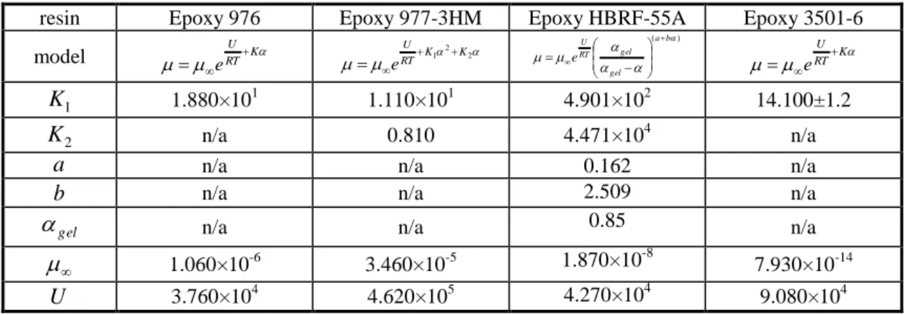
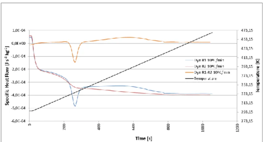
4.2.1. Resins Cure Kinetics ... 106
4.2.1.1. Experimental Procedure ... 106
4.2.1.2. Characterization/Modelling of Two Epoxy Systems ... 108
4.2.2. Resins Rheological Behaviour ... 135
4.2.2.1. Experimental Procedures ... 136
4.2.2.2. Characterization/Modelling of Two Epoxy Systems ... 139
4.2.3. Resins Mixing Behaviour ... 163
4.2.3.1. Experimental Procedures ... 163
4.2.3.2. Experimental Results ... 164
4.2.4. Process Related Input Variables ... 174
4.2.5. Material Related Input Variables ... 177
4.2.6. Unmeasured Input Variables ... 179
4.3. Experimental Validation of Model Output... 180
4.3.1. Wet Filament Winding Monitoring Setup ... 180
4.3.2. Radial Pressure ... 185
4.3.3. Resin Flow... 187
4.3.4. Compaction of the Laminate ... 191
4.3.5. Relative Phases Content ... 194
4.3.6. Resin Mixing ... 196
4.3.7. Fibre Waviness ... 197
CHAPTER 5 NUMERICAL IMPLEMENTATION AND VALIDATION... 201
5.1. Objectives and Methods ... 202
5.2. Discretization of the Analytical Descriptions ... 204
5.2.1. Resin Flow Sub-Model... 204
5.2.2. Fibre Bed Compaction Sub-Model ... 204
5.2.3. Heat Transfer Sub-Model ... 205
5.2.4. Resin Cure/Crystallization Sub-Model ... 205
5.3. Numerical Code... 206
5.4. Sensitivity and Compatibility Tests ... 207
5.4.1. Early Code Debugging ... 207
5.4.2. Qualitative Behaviour Evaluations... 209
5.5 Validation of the Process Model ... 212
5.5.1. Comparison of Experimental and Numerical Results ... 212
5.5.2. Advantages/Disadvantages of the Adopted Methodology ... 221
5.5.3. Assumptions and Limitations ... 222
5.5.4. Process Model Validity ... 222
CHAPTER 6 CONCLUSIONS ... 225
6.1. Objectives vs Results ... 226
6.2. With Respect to the State of the Art ... 232
6.3. Future Work ... 234
CHAPTER 1
INTRODUCTION
1.1. Motivations and Objectives
The filament winding (FW) process, used for the manufacture of a wide variety of composite parts and components, has proved to be technically effective and cost competitive through the last few decades. For specific emergent and high demanding applications, it turns to be the most appropriate manufacturing process. Axis-symmetric composite parts like sewage or supply piping systems, high pressure vessels, water storage tanks, aircraft fuselage sections, transmission shafts, fishing rods, golf club shafts but also non axis-symmetric ones like wind turbine blades, buses chassis are among these identified applications.
The FW manufacturing process consists of an automated process in which an impregnated continuous filament (or tape) tow is wound over a rotating mandrel. The synchronized movement of both this mandrel and the delivery head in its moving carriage controls the fibre path, leading to the desired pattern. In Figure 1 the typical configuration of this process (wet winding) is schematically represented. In it, one may observe that in the case of axis-symmetric parts, in such typical process configuration, the main axis of symmetry of the composite component is coincident with the rotation axis of the mandrel. Different process configurations mainly differ in the type of material used (thermosetting prepregs, thermoplastic prepregs, etc) for which different impregnation and feeding systems may be designed.
Figure 1 – Schematic view of wet FW process [1].
By controlling the relative amounts of resin and reinforcement, the winding pattern, the fibre’s tension, the cure of the resin system, as well as other important variables of the process, the strength of the filament wound parts may be improved to resist stresses and/or strains in specific directions. Thus, the simultaneous interaction of a great number of complex physical phenomena is of difficult assessment in terms of its
modelling and precise measurement. However, with the increasing demands on safety and reliability issues, in short- as well as in long-term applications, it is of absolute need to achieve better knowledge and more accurate models of the physical phenomena acting in the FW process. Only realistic models, capable of relating the input with the output relevant parameters of this multi-physical process will allow a reliable design and control of the FW manufacturing process for each application. A better understanding of the coupled behaviour of those phenomena and of their influence on the final quality of the manufactured parts will, ultimately, allow to optimize them and achieve weight and costs savings in the final products. Questions on the level of reproducibility, predictability and dimensional tolerances may also be further addressed.
This study aimed at developing and validating a multi-physical process model for the FW manufacturing technique. A modular approach, based on sub-models each referring to a relevant group of physical phenomena acting at the layer-laminate level, was designed. This option allowed to settle a model applicable to a broader range of real configurations and applications of the FW manufacturing process as it is now required by the industry.
1.2. Thesis Organization
This thesis is divided into six chapters, each addressing a relevant stage within the development and analysis of the present process model. Each chapter is built independently both thematically and in the logical arguments construction. However, the six chapters report the natural sequence of the whole study, from the problem identification, to the proposition of a solution and its validation.
After this introductory chapter (chapter 1) a comprehensive literature review is set in chapter 2. In this review, the available knowledge on processes and/or sub-processes that correlate with the FW process are identified. Several works published by different authors in the past are critically analysed and the background for this study is therefore enriched. In chapter 3 the FW process model is established. The several physical phenomena acting within the laminate being manufactured are analytically modelled. Each decoupled group of phenomena is described in a dedicated sub-model. The overall architecture of the multi-physical process model is also presented. The experimental tests conducted to assess and measure the evolution of the several physical parameters during the FW process are fully addressed in chapter 4. This chapter holds the detailed description of the experimental procedures and respective results, covering the main process input and output variables. Critical analysis of these results is produced in view of comparing with the numerical ones. Chapter 5 covers the numerical implementation of the process model. Several sub-routines, each relating to a sub-model, are coded into numerical algorithms. These are assembled through a main routine that guarantees the proper flow of variables information and interaction between the several sub-routines accordingly with the model architecture defined. At the end of this chapter, critical comparisons between numerical and experimental results are presented and the validation of the process model is, thus, discussed. In chapter 6, the conclusions are drawn for the entire study. The degree of accomplishment of the objectives and thus the usefulness and validity of the present work are discussed. Future improvements and developments to be further addressed are identified as well.
CHAPTER 2
LITERATURE REVIEW
2.1. Scope of the Review
In this chapter the state of the art referred to the FW process modelling and characterization is addressed through a comprehensive literature review of relevant technical and scientific papers and thesis published in the last four decades. Previous works covering all the relevant fields related to the modelling of this process were studied. Very few researchers focused strictly in the FW process. On the other hand, however, a considerable number of studies led on other processes and/or the detailed characterization of several of the physical and chemical phenomena acting within consolidating composite laminates have been published.
The review is divided in the main sub-themes that correspond to the different physical phenomena governing the consolidation and behaviour of composite laminates. Namely, identification of the FW process parameters, fibre’s compaction, resin flow, resin kinetics, stress-strain and global process models are critically identified and described in separated sections. Despite the coupled nature of some mechanisms in the consolidation of composite laminates, independent sections deal with each group of phenomena identified in order to allow a deep understanding of them. Since different authors referred to similar phenomena with different nomenclature or even mathematical symbols, effort is made in homogenizing the relevant information and presenting it in the symbology and nomenclature adopted in the present work. For clarity, the matrix is frequently named resin, independently of thermosetting and/or thermoplastic being considered throughout this chapter. Experimental techniques for the measurement of parameters and/or model validation which are thought relevant for the present study were also reviewed from the literature.
Since the scope of the present thesis is to model a multi-physical process that involves a broad range of correlated research fields, contributions from a wide range of sources are studied. Therefore, although the following literature review may appear reasonably extensive, it strictly covers the relevant knowledge that supports the strategy for the development and establishment of the present FW process model. Further detailed analysis is addressed in chapter 3, when setting the assumptions and formulations of each sub-model.
2.2. Process Modelling in Composites Manufacturing
In this section, the literature addressing the theoretical modelling of each phenomenon governing the behaviour of composite laminates under consolidation is critically reviewed. An overview of the main studies published in the last four decades is drawn. As far as possible, the review is divided in the relevant sub-themes as mentioned above. The sub-themes were chosen upon identification of the process parameters and/or variables which govern it.2.2.1. Process Parameters
In the FW manufacturing process there are several physical parameters whose different combinations allow a wide range of mechanical and geometrical results. These parameters may be divided into two categories: the user-controllable process parameters and the other process parameters inherent to the physics of the process. By user it is meant the designer and/or operator of the manufacturing process. In a process model development, the final objective is to get the user-controllable process parameters to be the input variables and the inherent variables (which are not directly controllable throughout the process) to be the output ones. Only with sound and correct physical descriptions of each phenomenon one may get a profitable tool for design and process optimization purposes.
The main user-controllable process parameters are:
the choice of the material system (the reinforcing fibres and the matrix); the geometry of the mandrel;
the initial fibre’s tension;
the cross-section of the fibre’s bundle (incl. bandwidth and/or thickness); the path of the fibres onto the mandrel;
the winding angle;
the initial fibre’s degree of impregnation; the processing temperature;
the winding speed; the lay-up sequence; and the curing time after winding.
The main process inherent parameters or phenomena are typically variable during the process, may vary with time and space, and are:
the fibre’s motion;
the matrix flow through the fibre’s bed;
the matrix degree of conversion (cure/crystallization); the matrix viscosity;
the stresses and strains in the fibres; the temperature;
the fibre’s, resin and void’s volume fraction; and the fibre characteristic waviness.
A few more parameters could be pointed out, such as the permeability of the fibre bed to the resin and air, or the layer’s interaction by way of the compaction pressure and
resin mixing. However, these may be identified as sub-parameters that influence the main ones previously identified. Moreover, these sub-parameters need to be specifically analysed in each case as they are highly dependent on the material system used together with other main configuration options for the FW process.
Lee and Springer [2] summarized the critical issues to consider when selecting the proper combination of the input variables. Thus, for most of the applications, the values of the controllable process variables must be selected such that:
the temperature inside the material is below the maximum allowable value at any time during processing;
the material is cured completely and uniformly;
at the end of the cure the fibre distribution is uniform and has the desired value;
the fibre tension is positive, but doesn’t exceed prescribed limits at any time during processing;
the cured composite has the lowest possible residual stresses;
the cured composite’s total residual strains are within the prescribed limits; the cured composite has the lowest possible void content;
the processing is executed in the shortest possible time.
It becomes clear that, either for process model validation or manufacturing purposes, considerable set of measuring devices is needed in order to guarantee that the user-controllable process variables really are within the admissible ranges and combinations that lead the outputs to the desired optimum values.
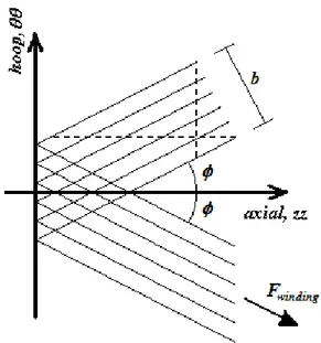
Relatively to the winding patterns, there are mainly three types of winding: circumferential (hoop), polar (longitudinal) and helical winding (Figure 2). The helical winding, if neglecting shear strength between surfaces (friction factor virtually null), implies the deposition of the fibres along a geodesic isotensional trajectory. In such condition, Clairaut’s theorem [3] may be expressed as follows:
nt consta
rsin , (2.1)
where r is the radial coordinate of the fibre bundle and
is the winding angle. The geodesic trajectories defined as in the equation (2.1) typically don’t correspond to the principal stress directions of the composite part when 0º90º. Further attention is given to this problem in section 2.2.5. In polar winding, on the other hand, one may experience considerable difference (from 12% up to 40% of the maximum value) on the fibre’s tension in the edges (callouts or domes) or in the mid-section (cylindrical) of the composite part [4]. In this case the isotensoidal assumption is not valid anymore.Analytical and numerical solutions for the kinematics of FW have extensively been investigated during the last decades. Koussios et al. [5,6] recently proposed consensual and updated kinematical models for ellipsoidal and cylindrical wound parts.
One specific manufacturing effect of the FW process is its mosaic patterned composite layer, as depicted in Figure 3. This particular formation of the lay-up can significantly affect the stress and strain fields in a thin-walled shell. However, it is not considered in the general stress analysis procedures, including the existing finite element software packages [7]. Stress analysis based on the conventional mechanics of laminated structures can underestimate the actual level of stresses in the thin-walled filament-wound composite shells. Pagano and Whitney [8] suggested that the stress
field within a highly anisotropic cylinder, even under simple loading conditions, is far from uniform.
Figure 2 – Schematic representation of circumferential (hoop) winding (top left), polar (longitudinal) winding (top right) and helical winding (bottom) [ 9].
Each filament-wound layer is typically composed by two plies with
and
fibre’s orientation angles, respectively. As these plies are interlaced throughout the part being wound they are actually identified as a single layer. Morozov [7] studied this characteristic of the FW process and showed how this structural feature affected the strength of the composite parts. He modelled the composite material in a mosaic way where each alternating triangle was defined as either [ ] or [ ].Figure 3 - Angle-ply layer of a filament wound shell [7].
Different configurations of the manufacturing process, whether it is used a thermosetting or a thermoplastic matrix system, will greatly influence the degree of homogeneity of the impregnation as well as the processing temperature. Furthermore, the interaction between layers (adhesion and exchange of mass and heat) and the
consolidation of the laminate is strongly dependent of the matrix properties. In the next sections, whenever the choice of the matrix type is critical, it is discussed in detail.
2.2.2. Compaction of the Fibres
The winding tension applied to the fibres during the FW process has an indirect influence on the fibre volume fraction and void content. Higher tension causes higher pressure build-up and as a consequence higher amounts of resin and voids are squeezed through or outwards the laminate. The fibre volume fraction increases and the fibre bed becomes stiffer. However, when the fibres’ content is too high there might be lack of matrix to keep fibres together and part performance may decrease significantly.
Several authors studied the pressure build-up phenomenon in self-acting foil bearings in the past century [10-13]. These systems present some similarities with the FW process and are, thus, worth observing. Blok and Rossum [10] have shown that a flexible impermeable tape in contact with a rotating cylinder and lubricating oil would cause the oil pressure to increase between the tape and the cylinder in a wedge-shaped entrance region (Figure 4). Following the wedge-shaped entrance region, the oil was observed to form a constant thickness film gap between tape and cylinder. For a wide range of test conditions, the outward oil pressure, p, in this constant thickness region was observed to be equal to the inward compressive stress, , given by:
r b
F
, (2.2)
where F is the inlet tape force, b is the tape bandwidth and ris the pin radius.
Figure 4 – Schematic cross-sectional of a tape being pulled over a cylindrical pin. The pressure build-up in the wedge entrance is also shown [14].
Similar relations between the constant thickness and processing parameters such as tape tension, width, oil viscosity, relative tape/cylinder speed and cylinder radius were presented by all those researchers. They developed the “lubrication number” concept. It is clear from the preceding analysis that fibre tension plays an important role in pressure build-up in such a fibres/mandrel interaction.
Bates et al. [14,15] studied the pressure build-up during melt impregnation of glass-fibre roving. They set the melt pressure at the roving/pin interface to be given by:
r b
F f
p , (2.3)
where f is an adjustable fitting parameter that can vary between 0 (no pressure at the interface) and 1 (maximum pressure at the interface). A f value equal to 1 would indicate that the outward melt pressure balances the inward compressive stress. For this value of f , there would be no normal force of the roving against the pin surface. A f value less than 1 would indicate that the roving is in partial contact with the pin. In Figure 5 a schematic view of the roving/pin interaction.
Figure 5 – Schematic transverse cross-section representation of the glass-fibre filaments interacting with the pin and the impregnating melt [14].
In a more general and widely accepted analysis for the pressure born in a composite laminate being processed, the externally applied pressure during its consolidation is shared by the fibre bed and the resin, which can be expressed by [16-22]: f r p p , (2.4)
where is now the applied stress, pr is the resin pressure and pf is the effective stress
sustained by the fibres. A simple viscoelastic system, in which the resin flow and fibre bed compaction are the viscous and the elastic components, respectively, is schematically represented in Figure 6. Theoretically, in a very low fibre volume fraction prepreg, or perhaps in a system with ideal straight fibres, the fibre bed carries no through the thickness stress. In practice, the relatively high fibre volume fraction, and the wavy geometry of real fibre beds mean, significant stress can be borne by the fibre bed, especially if there is any loss of resin [18].
Figure 6 – Analogue representation of composite laminate with elastic (fibre) and viscous (resin) response [18].
The compaction curve of the fibre bed is the relationship between the effective stress, pf , and the degree of fibre bed deformation, which is typically associated to the
fibre bed thickness, tfb, and fibre volume fraction, Vf. Experimental techniques and
methods previously published are reviewed in section 2.3.1.
Lee and Springer [23] retrieved from the physics of winding that the pressure applied by the j1 layer to the outside of the previously wound layer, j, is given by:
1 1 2 1 sin j j f j j out b r F p , (2.5)
where F is the winding fibre tension, is the layer winding angle, rf is the fibre radial
position (radius to the middle of the layer) and b is the tow/bundle bandwidth. In modelling the successive deposition of n new layers in the FW process, incremental application of the pressure in each deposed layer can be done with a series of
n equal increments or other criteria can be adopted. Banerjee et al. [24] coded this phenomena numerically and found several restrictions to the size of each increment to compute.
During the FW process, the fibre’s tension may vary from the initial winding tension due to [23]:
inward radial motion of the fibres through the resin resulting in a reduction in fibre tension;
radial and axial expansions or contractions of the composite due to thermal or shrinkage effects resulting in an increase or decrease in fibre tension. The second group of causes is further reviewed in sections 2.2.4 and 2.2.5. Concerning the fibre motion in each layer, it occurs during the winding process from the deposition of the layer up to the moment in which fibres either are fully accommodated or cannot accommodate further due to the pressure gradient and/or matrix state. If the matrix reaches a certain level of viscosity that hinders fibres to move before the pressure drop is complete, then a resin pressure gradient will remain in the laminate at and after this point [25]. In thermosetting resin systems this would be the gelation point.
Banerjee et al. [24] developed a fibre motion model for wet FW which described the motion of each layer of the cylinder during winding. This model was based on the assumption that resin reached gelation prior to eventual oven curing phase, i.e., that the fibres motion ceased prior to any external thermal loading that would affect the behaviour of the accommodating laminate. In particular, a process model relating the winding processing conditions (user-controllable parameters) to the fibre volume fraction was presented. According to their study, two phenomena are acting together in the fibre motion:
as a new layer is wound, an external pressure is applied, creating a pressure gradient in the previously wound layers (equation (2.5)); this load is shared between the fibre and the resin (equation (2.4));
the fibre bed behaves as a nonlinear spring and when compressed by the external force applied when a layer is wound, it compacts itself (Figure 6).
A specific case of sponge squeeze model, previously developed by Gutowski et
al. [26] (and reviewed in section 2.2.6), was considered in their study:
as the resin cured, fibre motion ceased in a particular layer; resin in adjacent layers had different viscosities;
a modified stiffness formulation was adopted.
In Figure 7 the fibre bed compaction mechanism, as considered to occur by these authors, is schematically represented.
Figure 7 - Compaction during FW. When the k+1 layer is wound, the layers beneath are subjected to a compressive load [24].
The fibre bed stiffness is a function of the fibre volume fraction which changes as the bed compacts, the stiffness must be re-evaluated. The evaluation of the fiber bed stiffness was done through a modified formulation presented by Cai and Gutowski [16,27] in which the fibre volume fraction, Vf, is the only variable influencing its evolution during the consolidation phase. The longitudinal, Exxfb, and transverse (bulk),
bb
E , on-axis stiffnesses were then expressed as:
5 4 0 4 1 3 4 5 f a f f a f f a fb zz fb yy bb a f f fb xx V V E V V V V V V E E E V E V E , (2.6) where fb yy E and fb zz
E are, respectively, the in-plane and out-of-plane transverse stiffnesses of the fibre bed, Ef is the Young’s modulus of the fibre, and
0
V , Va and are constants dependent on the state of the fibre bundle.
Once the layer displacements uj are determined for the mth load increment, the radial positions of the layers in place jl..k are updated as follows:
j m j
m i m j i m j m j o m j o u r r u r r ) 1 ( 1 ) ( 1 , (2.7) where j o r and j ir are the outer and inner radii of the jth layer, respectively.
Figure 8 schematically represents the fibre motion model philosophy developed by Banerjee et al.[24].
Figure 8 - Schematic showing the inputs and outputs of the FW model and the relationships among sub-models [24].
Gutowski and Dillon [28] proposed a fibre bed compaction model that fitted all the compaction curves previously published by different authors for different laminates. These experimental studies are reviewed in section 2.3.2.
Dave et al. [29,30] divided the process of (graphite) fibre bed compaction into three different deformation behaviours. They plotted void ratio as a function of the effective stress for effective stress range of 0 to 1.7MPa. In the range of 0 to 0.07MPa fibre bed has a linear behaviour, which is called “immediate or distortion settlement” behaviour. It occurs together with load application, primarily as a consequence of distortion within the packed fibre bed. In range of 0.07MPa to 1.03MPa the fibre bed has a semi-logarithmic behaviour. It is called “primary compression” or “normal consolidation”. Afterwards, over the range of 1.03MPa, bed fibre behaves like a rapidly stiffening spring. It is called “secondary compression” or “over consolidation” and is described as being due to plastic flow and gradual adjustment under imposed load.
They presented a relationship between the fibre volume fraction, Vf, and the effective stress sustained by the fibre bed, p , that in the range f 0 pf 0.0687MPa
had the following form [30]:
0 6 10 5519 . 1 1 1 e p V f f , (2.8)
Following Cai and Gutowski’s work [16,26,27,31], Agah-Tehrani and Teng [32] proposed a continuum consolidation model for macroscopic analysis of fibre motion during FW of thermosetting cylinders of arbitrary thickness. Their model was limited to winding at a constant (hoop) winding angle throughout the process and constant viscosity resins. The model indicated one zone in which consolidation has ceased and one other in which fibre bundles were continuing to compact due to the applied tension. Hojjati and Hoa [33] and Shin and Hahn [20] also followed and applied Gutowski’s continuum equation governing the through-the-thickness compaction behaviour (one-dimensional, r) of consolidating laminates as follows:
2 2 2 r p S W V t pr f r , (2.9)
where pr is the resin pressure, W and S are the tangent compliance and the permeability of the fibre bed, respectively, is the resin viscosity. The tangent compliance described a change in the fibre volume fraction resulting from a change in the effective compressive fibre stress.
Gutowski et al. [34] derived several alternative expressions relating fibre effective stress, pf , to the fibre volume fraction, Vf, based upon the assumption that the fibre
network stiffness was governed by the bending beam behaviour of the fibre between multiple contact points. The most widely used by several authors is the following formulation: 4 0 4 1 1 3 f a f f V V V V E p , (2.10)
where V0 is a certain “minimum” fibre volume fraction bellow which the fibres carry no
load, Va is the maximum available fibre volume fraction at which resin flow stops, is the typical waviness ratio (span length/span height) of the fibres and E is the flexural modulus of the fibres.
The lamina stress-strain behaviour has been found to greatly influence the compaction behaviour of the laminate during its consolidation. Laminae with hardening stress-strain behaviour, which is characteristic of real composite layered laminates, have the fastest compaction times [35]. Although this output comes from studies conducted in autoclave/vacuum degassing processes, attention must be given to it. Specific stress-strain constitutive relations are discussed in section 2.2.5.
2.2.3. Resin Flow
Resin flow is the other mechanism (adding to those described in the previous section) that greatly influences the fibre motion and positioning within the layers during FW process. Although in the FW process modelling the resin (matrix) flow and/or cure phenomenological sub-models cannot be separated from the fibre motion sub-models,
here we try to summarize them in a decoupled manner. This option is supported by the fact that the resin flow is itself a physical process that can be independently described analytically.
The fluid flow through porous media has been extensively studied in the past. Numerous studies have been published concerning the modelling and characterization of such phenomenon. Among those, soils consolidation, filters behaviour and impregnation of fibrous beds were the most studied. From them, relevant knowledge was gathered to the “recent” composites manufacturing processes.
Ó Brádaigh et al. [36] divided the flow in composites during consolidation in two major mechanisms: percolation flow and shear flow. These mechanisms are schematically depicted in Figure 9. For percolation flow, applying pressure to the laminate is similar to squeezing a sponge that causes the fluid to bleed out. For shear flow, the composite behaves as a very viscous fluid filled with inextensible fibres. In this case the resin and fibres move together and the driving force is the deviatoric component of the stress applied to the laminate.
Figure 9 - Flow mechanisms during processing: (a) percolation and (b) shear [36].
Typically, the percolation flow approach is used to model the flow and compaction of thermosetting matrix composites and the shear flow approach is applied to thermoplastic matrix composites [37].
Kyan et al. [38] modelled the resin flow through a fibre bed, using a geometrical model of the fibrous bed and assuming that, despite the level of porosity, the fluid was not flowing through a significant portion of the pores space.
Lindt [39] presented analytical descriptions of the slow consolidation of fibres in a Newtonian fluid. He developed the lubrication theory, in which, for low Reynolds and narrow channels flow through the fibre bed, the mechanisms of squeezing and drag flow may be separated as they govern the flow in different regions of the porous media. However, several assumptions were made that do not comply with typical composite fibre beds properties. Namely the assumptions that the cylinders (fibres) must be in pure translation and have smooth surfaces.
Bear [40] suggested that there are two equations describing the unidirectional flow mechanism in porous media: the Darcy’s (1856) and the Forchheimer’s (1901) equations. These can be expressed as:
dr dp S u , (2.11) dr dp u d u d1 22 , (2.12)
where u is the fluid velocity, S is the permeability of the medium, is the fluid viscosity,
dr dp
is the pressure gradient in the direction of the flow. The terms d 1u and
2 2u
d vary with viscous and inertia effects, respectively. After the establishment of the Darcy’s [41] model for flow in porous media, Dupuit [42] and Forchheimer [43] included inertia effects for higher flow velocities.
Although the permeability tensor, Sij, is anisotropic for most fibre reinforcements it may be viewed as a scalar quantity, S, in one-dimensional (unidirectional) flow condition [21]. The use of Darcy’s type equation as presented above is, thus, suitable for one-dimensional, low Reynolds number flow through a fully saturated porous medium [44]. Flow throughout a fibre sheet in tension is a low Reynolds number flow (Re10). This equation can also be extended and applied to two- and three-dimensional flows [29]. The friction losses related to the superficial velocity of the fluid (resin) are inversely proportional to the aspect ratio of the obstacle (fibre). For high aspect ratios, rf L0.05, of the fibre, the relationship between the pressure gradient and the fluid velocity is nearly linear as the inertia effects are not significant at these low velocities. However, when the aspect ratio decreases (and thus the porosity increases) inertial effects become considerable [45].
Due to the increasing importance of composite manufacturing techniques, modelling the permeability of fibre beds was addressed by several research groups through the years. In fact, the parameters that govern the resin flow mechanism are the resin viscosity, the specific permeability of the media and the temperature [29,30]. The parameters related with the thermo-kinetics of the matrix are reviewed in section 2.2.4. The specific permeability, Si, in the ith direction for anisotropic materials can be
expressed as: i H i K r S 2 , (2.13)
where is the porosity of the porous medium, rH is the mean hydraulic radius of the
porous medium (cross-sectional area normal to flow divided by the perimeter wetted by the fluid), Ki is the corresponding Kozeny constant. The mean hydraulic radius of the
porous medium is given by [35]:
f m f f H V V r r r 2 1 2 . (2.14)From equations (2.13) and (2.14) the following expression for the through-the-thickness permeability of the fibre bed is obtained:
2 2 3 1 4 K r S f . (2.15)Equation (2.15) is actually the Kozeny-Carman model [46], originally developed for granular beds showing isotropic distribution, which can also be expressed as:
2 3 2 1 4 f f f V V K r S . (2.16)This model was extended to flow across arrays of cylinders by Gutowski and co-workers [27,47]. They suggested that once the j1 layer had passed through the resin rich region, the layer itself compacts. The flow resistance of the fibre network increased and the permeability dropped substantially. At a certain point before Vf 1 the flow must stop and this was not accomplished by the Kozeny-Carman model. Therefore, Gutowski and co-workers measured the maximum fibre volume fraction at which resin flow is no longer possible, Va', and a relationship between the transverse permeability, S, and fibre volume fraction, Vf, was developed as follows:
1 ' 1 ' ' 4 3 2 f a f a f V V V V K r S , (2.17) where f
r is the radius of the fibres, K' is a modified Kozeny constant. Kozeny constant, K, depends on tortuosity, defined as
Le L
2, where Le is the average effective path length that fluid particle passes from one end to the other end of the porous bed and L is the actual distance between two ends of the bed. Therefore, for flow through an anisotropic porous medium, like a bed of aligned fibres, the value of Kozeny constant in the direction of the fibres is quite different from that in the direction perpendicular to the fibres because the tortuosities in the two directions are different. This led these authors to obtain a modified value for the Kozeny constant by fitting of experimental data.Several authors presented considerably different values for the non-dimensional Kozeny constant related to the through-the-thickness flow direction. Dave et al. [29,30] utilized the value previously presented by Sullivan [48] of K6. Using this value, Smith [35] calculated a permeability of S4.331013m2 from equation (2.15). The value previously reported by Loos and Springer [49] of S5.81016m2 (103 lower) suggests that the Kozeny’s constant must be much higher than K6. Gutowski et al. [47] and Lam and Kardos [50] reported K11 and K150 as the reference values, thus supporting this observance.
Springer [51] studied the relationship between the applied pressure and the resin flow during the cure of fibre-reinforced composites, where the layers were found to consolidate in a wavelike manner. Loos and Springer [49] developed resin flow and void models of the curing process. The resin velocity was related to the pressure gradient, fibre permeability and resin viscosity through the Darcy’s type equation for flow in porous media (equation (2.11)).
For aligned cylinders, analytical models based on drag, or on the lubrication approach, were developed for Newtonian and generalized fluids by several authors [52-58]. Some of these are available for low porosity, others for high porosity values.
Happel and Brenner [54] developed analytical solutions of the Navier-Stokes equation for flows parallel and normal to an array of cylinders of a given diameter. Sahraoui and Kaviany [57] used a finite-difference numerical method to solve the same equation for a two-dimensional (simultaneous) flow through an array of cylinders. They presented a relation between the permeability of the porous media, S, and its porosity,
, as follows:
0.4 0.8 1 4 0606 . 0 4 1 . 5 2 f r S , (2.18)where rfis the radius of the fibres.
Sangani and Acrivos [55] established the following relationship between the transverse permeability, S, of circular tows arranged in hexagonal arrays and the fibre volume fraction, Vf: 2 5 3 2 1 2 27 1 2 f f f V V r S . (2.19)
These models have shown a rather good agreement with experiments [59,60]. The correct modelling of the tow cross-section is also of great importance because of its influence on the resin flow and, consequently, in the fibre’s compaction behaviour and interaction between layers. Sherrer [61] compared both the rectangular fibre model of Cutler (1961) and the hexagonally arranged Hashin’s fibre model (1964) with experimental data obtained in his compression, torsion and tension tests conducted on cylindrical wound specimens. Both Cutler’s and Hashin’s models presented relevant limitations due to their restrictive assumptions and results were not satisfactory.
Looking to the topology of the fibre tows when being wound, it is commonly accepted that they present an elliptical cross-section shape. In conventional FW configurations, the fibre bundle incorporates several fibre tows each including several hundreds or thousands of individual filaments. The higher the winding force is, the cross-sectional shape of each tow becomes more flattened, thus approximating the bundle cross-section to a homogenous random distribution of individual cylindrical filaments. However, in the conventional range of winding forces, the tow elliptical cross-section and individuality may govern the permeability characteristic of the fibre bed. Some studies intended to approach these topologies. Epstein and Masliyah [62]
numerically solved the problem of normal flow through elliptical fibres by extending both the Happel and Brenner [54] free surface and the Kuwabara [52] zero vorticity cell models. They showed that fibres with an aspect ratio of 5:1 have a permeability that is 75% lower than obtained for circular fibres when the major axis is perpendicular to the flow as is the case in transverse permeability measurements (and of FW). The volume fractions studied were above 10%, since for lower volume fractions the cross-section exerted a minor effect.
Later, the increasing importance of liquid moulding techniques using fabrics led to the development of further models, which took into account not only the ellipticity of the fibre tows, but also their intrinsic permeability. Phelan and Wise [63] proposed a semi-analytical model based on lubrication approximation, and validated it with computational fluid dynamics, and a few experimental observations. Ranganathan et al. [64] extended this model and proposed for a solid ellipse an empirical relationship of the form: B f f V V A b a S 1 max , (2.20)
where a and b are the axes of the ellipse, max
f
V the maximum packing fraction for a given packing geometry and A and B depend on the axes ratio. For example,
2 3max
f
V for a proportionally hexagonal packing. For the flow perpendicular to the large axis of the elliptical fibres, and a shape factor greater than 5, they proposed the following relationship: 62 . 2 max 2 0.67 1 f f V V b S . (2.21)
They extended this approach to porous tows, pointing out the use of a ‘‘nominal volume fraction’’, nominal
f
V , which refers to the volume occupied by the ellipses, and is related to the actual volume fraction, Vfactual, by:
tow f inal nom f actual f V V V , (0.22) where tow f
V is the volume fraction of fibres within a single tow. They showed that the intrinsic porosity of the elliptical tows does not exert much of an influence, until the ratio of the tow permeability over the overall permeability is greater than 0.001. This was later confirmed using boundary element methods (BEM) and computational fluid dynamics (CFD) calculations [65,66]. Extension of these models to the flow of non-Newtonian fluids was also presented [67].
In the FW process the phenomenon of resin flow is strongly related with tension applied to the fibre bundle during the winding that creates compaction gradient pressure in previously wound layers. This causes resin to squeeze and flow through the porous fibre bed [24]. As the fibre bed below compacts, the fibre volume fraction increases and
uncured excess resin from previously wound layers bleeds through the surface. When pressure inside laminate becomes equal to the pressure on its boundaries, there is no more resin flow, no further compaction of the bed, and the specific permeability in any particular direction is constant throughout the bed.
As Cai et al. [16] identified fibre bed compaction as being a dominant process in wet FW, they also defined the time required for the resin to flow through a certain ply/layer, tf. It was defined as:
* 4 202 f s f r A h K t t , (2.23) where *
t is a dimensionless time at which the fluid pressure drops substantially, f
r is the radius of the fibres, K is the Kozeny constant, is the fluid viscosity, h0 is the layer thickness and As is a fibre bed spring constant. For processing conditions in which the flow time, tf , is less than the winding time, tw, for a layer, the fluid (matrix) would
have ample time to flow through the compacting fibre bed.
Undulating channels (tubes) have also been used to model pore geometry in the study of flow through porous media. With its converging and diverging character, this model may avoid the difficulty of selecting representative fibre bed structures (Figure 10). Following previous work of Hjelming and Walker [68], Cheng and Chiao [69] simulated the fibre/resin system with two types of flow cells: the through-flow cell (Figure 11 a) and the squeezing-flow cell (Figure 11 b). The forces acting on the fibres were discriminated into a shear force due to resin flow and a hydrodynamic squeezing force caused by fibre compaction. Main assumptions adopted were:
the resin was considered a Newtonian fluid; no flow along occurred the fibres;
no slippage occurred at the resin/fibre interface; inertial and gravitational forces were negligible;
if using a very viscous resin the flow was treated as a two-dimensional quasi-steady state motion.
Figure 10 - Structure of random cylinder arrays during consolidation process [69].
The geometric parameters used in this undulating channels model need to be justified further to compare with experimental results.
Figure 11 - Geometry of the undulating channel for (a) through-flow cell, and (b) squeezing-flow cell [69].
Few models have been also presented to predict the impregnation and consolidation of thermoplastic composites [70-75]. These models typically applied the Darcy’s type equation (equation (2.11)) to model the flow of molten resin within the tows, with the flow direction assumed perpendicular to the fibres direction. All published models ignored void migration and dissolving of entrapped air into the thermoplastic matrix.
One interesting set of assumptions made on the impregnation sub-model developed by Sala and Cutolo [76,77], for thermoplastic powder-impregnated material winding, was that the overall resin movement consisted of three elementary fluxes:
an isotropic flux induced by a pressure gradient at the boundary of bundles;
a relative radial flux originated from inwards accommodation of the fibres towards the mandrel;
a tangential flux produced by bundle deformation due to external pressure. Part of this flow participated in the impregnation while part of it percolated through the interstices between the tows of fibres composing the bundle. The percentage of flow penetrating the fibre bundle was estimated by computing the ratio of permeabilities outside and inside the bundle (rich in filaments).
2.2.4. Resin Kinetics
In the composites manufacturing, the cure/crystallization kinetic characterization of the matrix have the main purpose of assessing its intrinsic properties such like the degree of cure/crystallization, or c, and the viscosity, . These properties are, typically, inter-related and depend on the thermal conditions and the state of the chemical cure (thermosettings) or re-crystallization (semi-crystalline thermoplastics). Therefore, heat transfer analysis and kinetic formulations for typical matrix systems have been studied by several authors and are reviewed herewith.
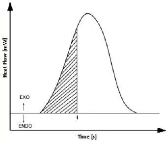
The degree of cure of a thermosetting resin, , is defined as the extent to which curing or hardening of a thermosetting resin has progressed, i.e., the degree of conversion of the resin molecules. It can be evaluated by the relative heat of reaction evolved until a certain time in the curing process and expressed as follows [49]:
u
H H
![Figure 18 – Schematic representation of cross-linking and volume change phenomena during the curing process of thermosetting resins [122]](https://thumb-eu.123doks.com/thumbv2/123dok_br/19178570.944270/55.892.217.779.588.828/figure-schematic-representation-linking-volume-phenomena-process-thermosetting.webp)
![Figure 32 – Thermal expansion behaviour of unidirectional laminate in the through the thickness direction [106]](https://thumb-eu.123doks.com/thumbv2/123dok_br/19178570.944270/78.892.194.593.428.735/figure-thermal-expansion-behaviour-unidirectional-laminate-thickness-direction.webp)